Golf Bag Incorporating Adjustable Shoulder Strap Assembly
Burgess; Ian ; et al.
U.S. patent application number 16/817822 was filed with the patent office on 2021-03-04 for golf bag incorporating adjustable shoulder strap assembly. This patent application is currently assigned to Acushnet Company. The applicant listed for this patent is Acushnet Company. Invention is credited to Ian Burgess, Duane Marshall.
| Application Number | 20210059388 16/817822 |
| Document ID | / |
| Family ID | 1000004717183 |
| Filed Date | 2021-03-04 |


View All Diagrams
| United States Patent Application | 20210059388 |
| Kind Code | A1 |
| Burgess; Ian ; et al. | March 4, 2021 |
GOLF BAG INCORPORATING ADJUSTABLE SHOULDER STRAP ASSEMBLY
Abstract
Golf bag and shoulder strap comprising: elongated tubular body for holding golf clubs; shoulder strap assembly comprising a pre-curved strap pad having a first end, a second end, and being configured to slidably receive a strap; the strap having a first strap end and a second strap end, each attached to the elongated tubular body; the pre-curved strap pad being positioned in a predetermined location on a wearer's front, shoulder and back when the golf bag is mounted on the wearer. Strap may be slidably received within a buckle and either (i) an interior channel that extends within the pre-curved strap pad between the first end and the second end; or (ii) slots and/or tabs that are positioned along a top exterior portion of the pre-curved strap pad that does not contact the wearer's front, shoulder and back when the golf bag is mounted on the wearer.
| Inventors: | Burgess; Ian; (Tiverton, RI) ; Marshall; Duane; (Greenwich, RI) | ||||||||||
| Applicant: |
|
||||||||||
|---|---|---|---|---|---|---|---|---|---|---|---|
| Assignee: | Acushnet Company Fairhaven MA |
||||||||||
| Family ID: | 1000004717183 | ||||||||||
| Appl. No.: | 16/817822 | ||||||||||
| Filed: | March 13, 2020 |
Related U.S. Patent Documents
| Application Number | Filing Date | Patent Number | ||
|---|---|---|---|---|
| 16556290 | Aug 30, 2019 | |||
| 16817822 | ||||
| Current U.S. Class: | 1/1 |
| Current CPC Class: | A45C 13/30 20130101; A63B 55/408 20151001; A45F 3/047 20130101 |
| International Class: | A45F 3/04 20060101 A45F003/04; A45C 13/30 20060101 A45C013/30; A63B 55/00 20060101 A63B055/00 |
Claims
1. A golf bag having a shoulder strap, comprising: an elongated tubular body for holding golf clubs; and a shoulder strap assembly comprising a pre-curved strap pad, the pre-curved strap pad having a first end, a second end, and is configured to slidably receive a strap; wherein the strap has a first strap end and a second strap end, each which is attached to the elongated tubular body; such that the pre-curved strap pad is positioned in a predetermined location on a wearer's front, shoulder and back when the golf bag is mounted on the wearer.
2. The golf bag of claim 1, wherein the strap is slidably received within an interior channel that extends within the pre-curved strap pad between the first end and the second end.
3. The golf bag of claim 1, wherein the strap is slidably received within slots and/or tabs that are positioned along a top exterior portion of the pre-curved strap pad that does not contact the wearer's front, shoulder and back when the golf bag is mounted on the wearer.
4. The golf bag having a shoulder strap of claim 1, wherein the strap threads each of the pre-curved strap pad and a buckle assembly.
5. The golf bag having a shoulder strap of claim 1, wherein the pre-curved strap pad comprises a sheath and a pre-curved support member that is at least partially comprised of a silicon composition and is enclosed within the sheath.
6. The golf bag having a shoulder strap pad of claim 3, wherein the sheath has an underside that contains surface texturing therein in a predetermined pattern that is configured to grip any surface that contacts the underside.
7. The golf bag having a shoulder strap of claim 1, wherein an underside of the pre-curved strap pad has a contour that at least partially matches and follows a contour of the wearer's body when the pre-curved strap pad is positioned in the predetermined location on the wearer's front, shoulder and back.
8. The golf bag having a shoulder strap of claim 2, wherein the first end of the pre-curved strap pad is tethered to the buckle assembly and the buckle assembly is operable with respect to each of the first end of the pre-curved strap pad and a portion of the strap that threads the buckle assembly to selectively adjust and set the position of the pre-curved strap pad into the predetermined location on the wearer's front, shoulder and back when the buckle assembly is in a closed position.
9. The golf bag having a shoulder strap of claim 6, wherein the buckle assembly is in a closed position when i) a first clamping member of the buckle assembly is rotated toward and forced and secured against a first portion of the strap threading the buckle assembly from a first direction thereby forcing and securing the first portion of the strap threading the buckle assembly against the first end of the pre-curved strap pad within the buckle assembly; and ii) a second clamping member of the buckle assembly is rotated toward and forced and secured against a second portion of the strap threading the buckle assembly from a second direction, thereby forcing and securing the first portion of the strap threading the buckle assembly against a second portion of the first end of the pre-curved strap pad within the buckle assembly.
10. The golf bag having a shoulder strap of claim 1, wherein the shoulder strap assembly comprises two pre-curved strap pads, two straps, and two buckle assemblies.
11. The golf bag having a shoulder strap of claim 8, wherein each strap threads a hub.
12. The golf bag having a shoulder strap of claim 9, wherein the hub is disposed between the second end of each pre-curved strap pad and the second strap end of each strap and slidably receives each strap in a criss-cross configuration.
13. The golf bag having a shoulder strap of claim 10, wherein the hub is positioned on the wearer's back when the golf bag is mounted on the wearer.
14. The golf bag having a shoulder strap of claim 1, wherein the strap is removably attached at least one end to the elongated tubular body.
15. The golf bag having a shoulder strap of claim 1, wherein the strap is slidably adjustable within the pre-curved strap pad while mounted on the wearer without changing the predetermined location.
Description
CROSS-REFERENCE TO RELATED APPLICATIONS
[0001] This application is a continuation-in part of co-pending U.S. patent application Ser. No. 16/556,290, filed on Aug. 30, 2019.
FIELD OF THE INVENTION
[0002] The present invention generally relates to golf bags having a single or dual shoulder strap assembly that is configured to be adjustable for positioning in a predetermined location on a wearer's front, shoulder and back when the golf bag is mounted on the wearer.
BACKGROUND OF THE INVENTION
[0003] Both professional and recreational golfers use their golf bags for many different purposes today. The bags are normally designed to carry clubs and balls, and accessories such as head covers, towels, hats, umbrellas, and golf tees. Many golf courses require that golfers walk the entire course and carry their own bags. Thus, the golfer is constantly placing the bag over his/her shoulders, removing the bag from their shoulders, and placing the bag down or standing-up the bag using a support leg mechanism on the bag. The golfer is also constantly removing and placing different clubs in the bag depending upon the shot being made. Thus, the golf bag and attached shoulder strap assembly needs to be durable, relatively lightweight, and comfortable when mounted on the wearer.
[0004] In this regard, a golf bag can be uncomfortable to carry when an attached shoulder strap isn't shaped and positioned ideally on the wearer's front, shoulder and back. In conventional golf bag and shoulder strap assemblies, each end of a flexible strap pad is tethered to a strap, with each strap also being attached to the golf bag. These straps can be loosened or tightened between the strap pad and golf bag to adjust the position of the golf bag with respect to the wearer. Unfortunately, it can be difficult to maintain a comfortable strap pad position on the wearer's front, shoulder and back when loosening or tightening a strap tethered/connected between the strap pad and golf bag.
[0005] Golf bag manufacturers therefore continuously seek to develop improved golf bag and shoulder strap assembly configurations which can solve this problem without meanwhile negatively impacting distribution of the bag's weight across the golfer's back on the course. Such improved golf bags and shoulder strap assemblies, if meanwhile durable and producible cost effectively within existing golf bag manufacturing processes, would be particularly useful and desirable. The current golf bag and adjustable shoulder strap assembly of the invention addresses and solves these needs.
BRIEF DESCRIPTION OF THE DRAWINGS
[0006] The novel features that are characteristic of the present invention are set forth in the appended claims. However, the preferred embodiments of the invention, together with further objects and attendant advantages, are best understood by reference to the following detailed description in connection with the accompanying drawings in which like numerals refer to like elements of the inventive golf bag:
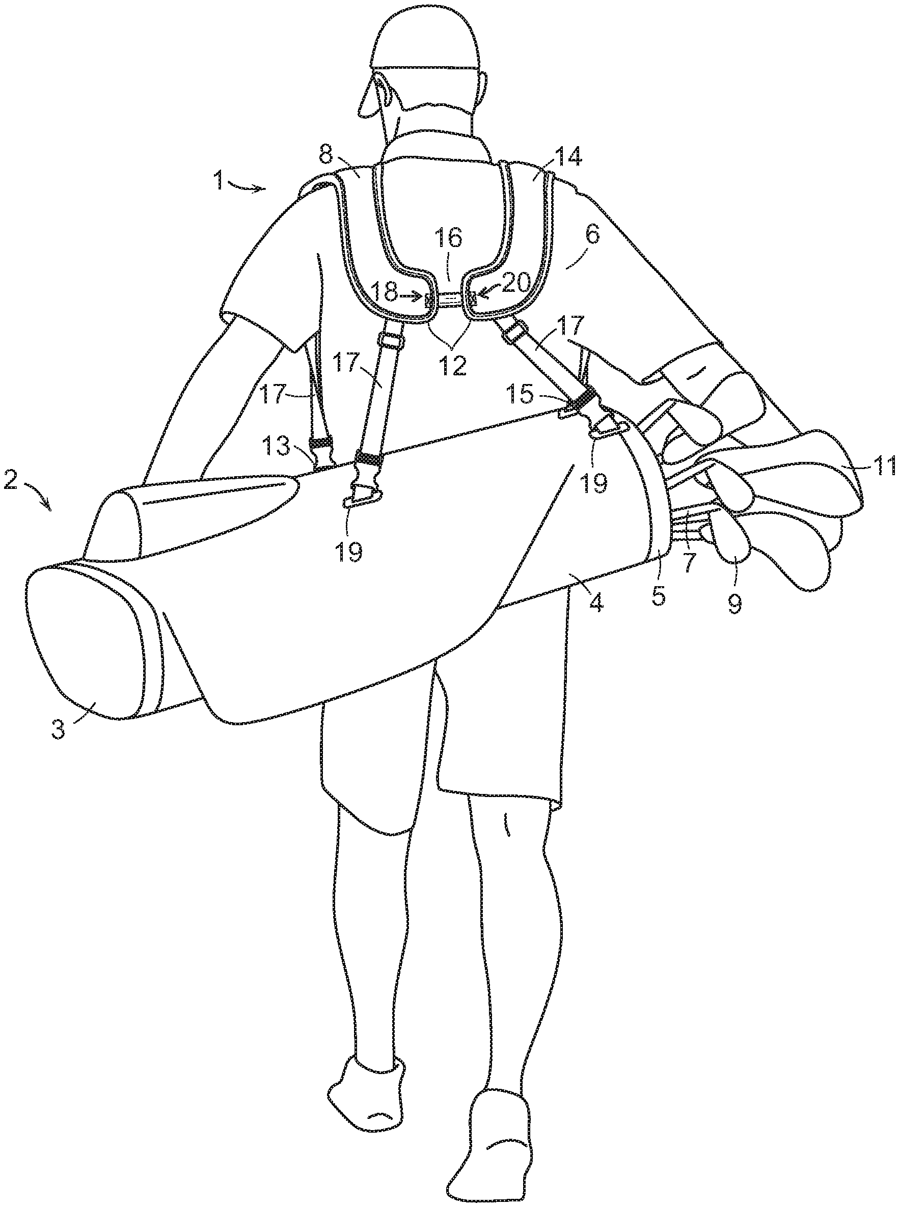
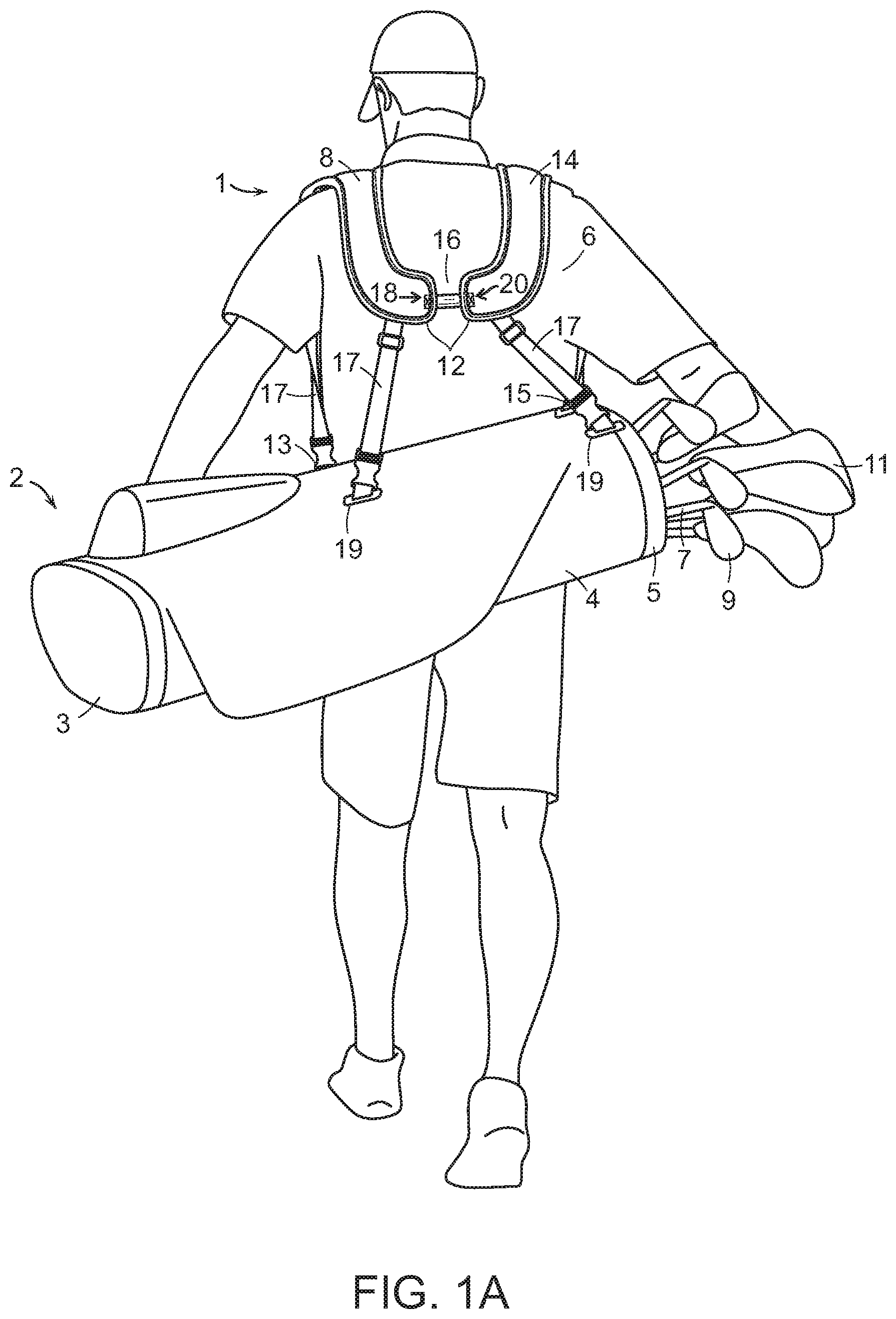
[0007] FIG. 1A is a rear perspective view of a person carrying a golf bag incorporating a dual shoulder strap assembly according to one embodiment of the invention;
[0008] FIG. 1B is a rear perspective view of a person carrying a golf bag incorporating a dual shoulder strap assembly according to another embodiment of the invention;
[0009] FIG. 1C is a rear perspective view of a person carrying a golf bag incorporating a dual shoulder strap assembly according to yet another embodiment of the invention;
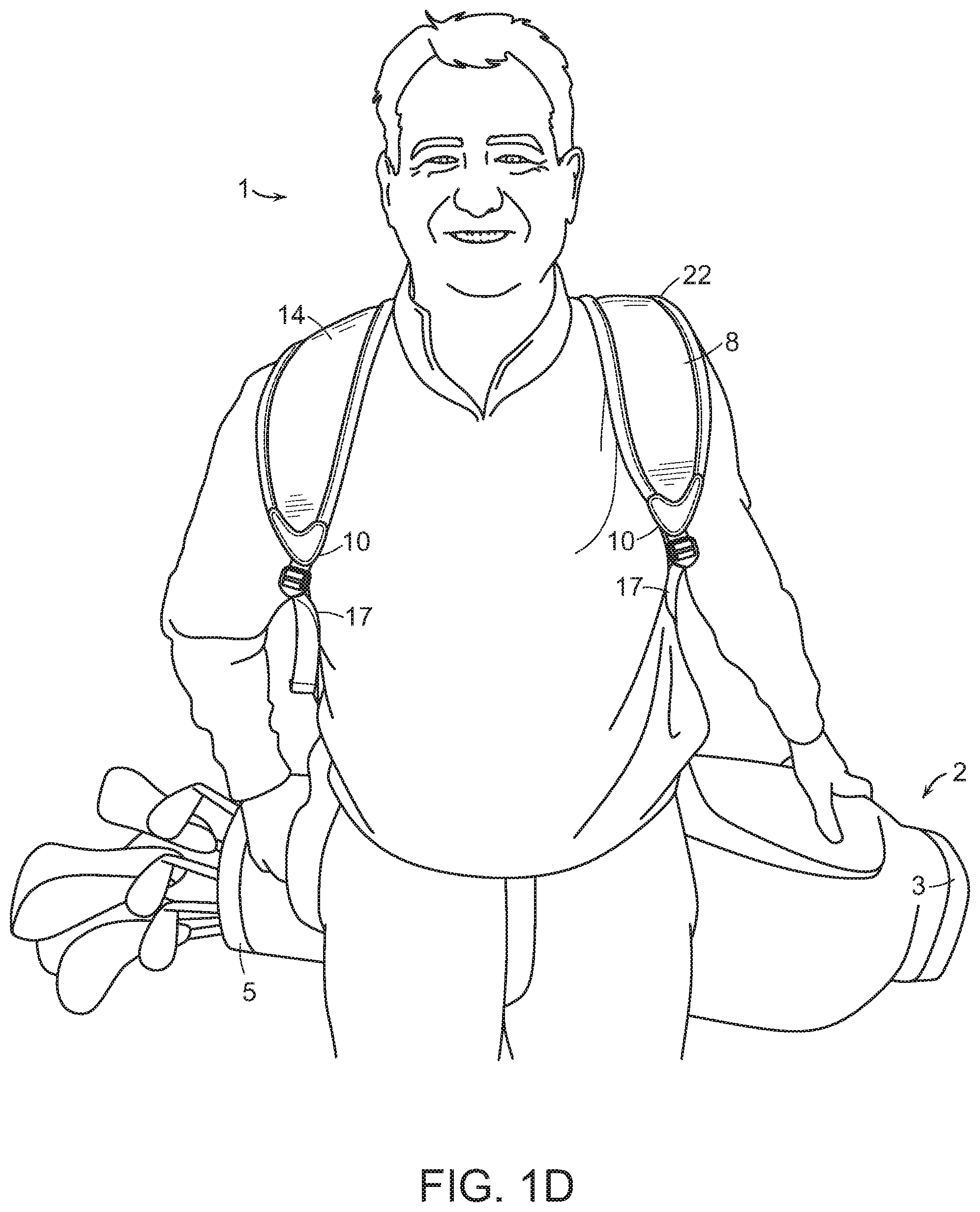
[0010] FIG. 1D is a front perspective view of a person carrying a golf bag incorporating a dual shoulder strap assembly according to any of the embodiments depicted in FIG. 1A, FIG. 1B or FIG. 1C;
[0011] FIG. 2A is a close-up view of the dual shoulder strap assembly depicted in FIG. 1A;
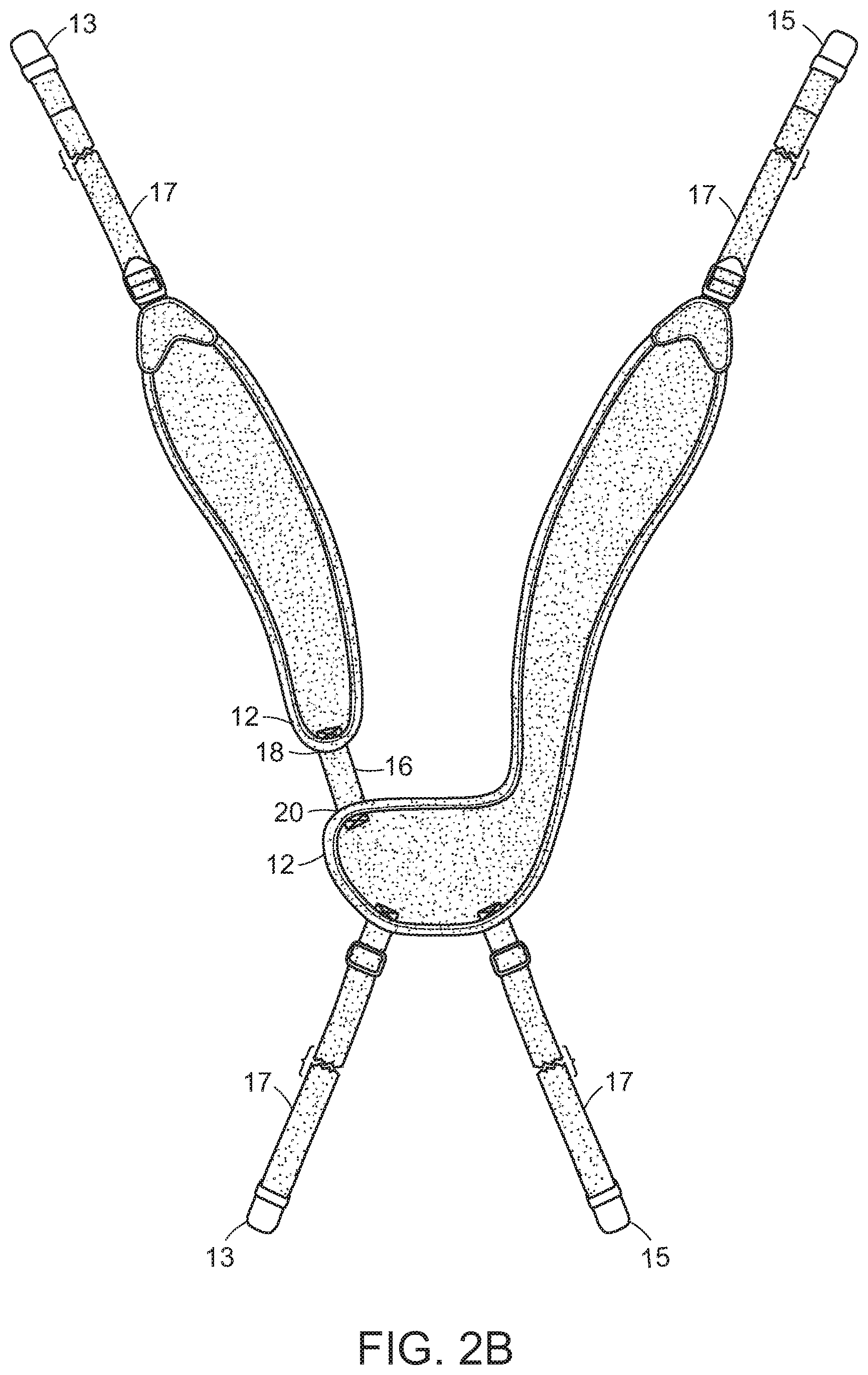
[0012] FIG. 2B is a close-up view of the dual shoulder strap assembly depicted in FIG. 1B;
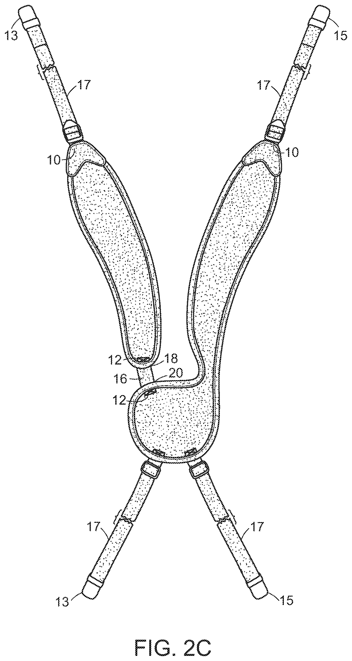
[0013] FIG. 2C is a close-up view of the dual shoulder strap assembly depicted in FIG. 1C;
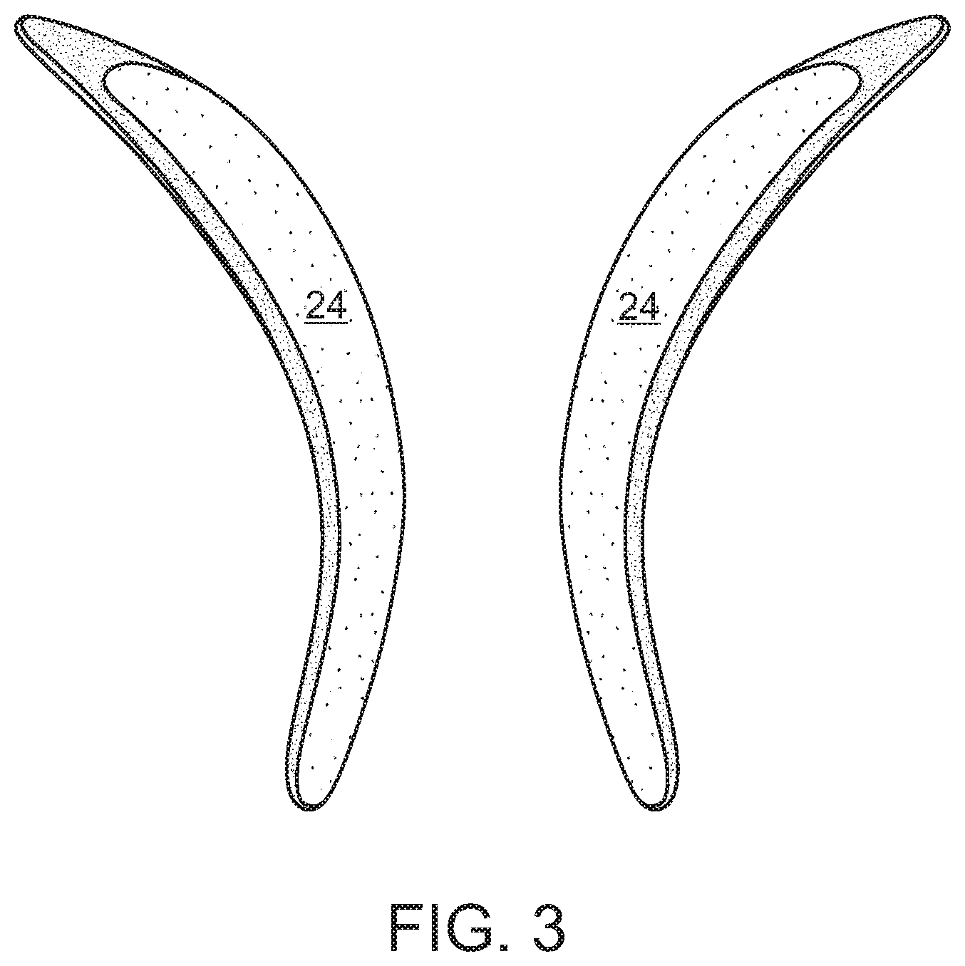
[0014] FIG. 3 is a close-up view of first and second support members having different lengths and being configured to be enclosed by a sheath according to one embodiment of the invention;
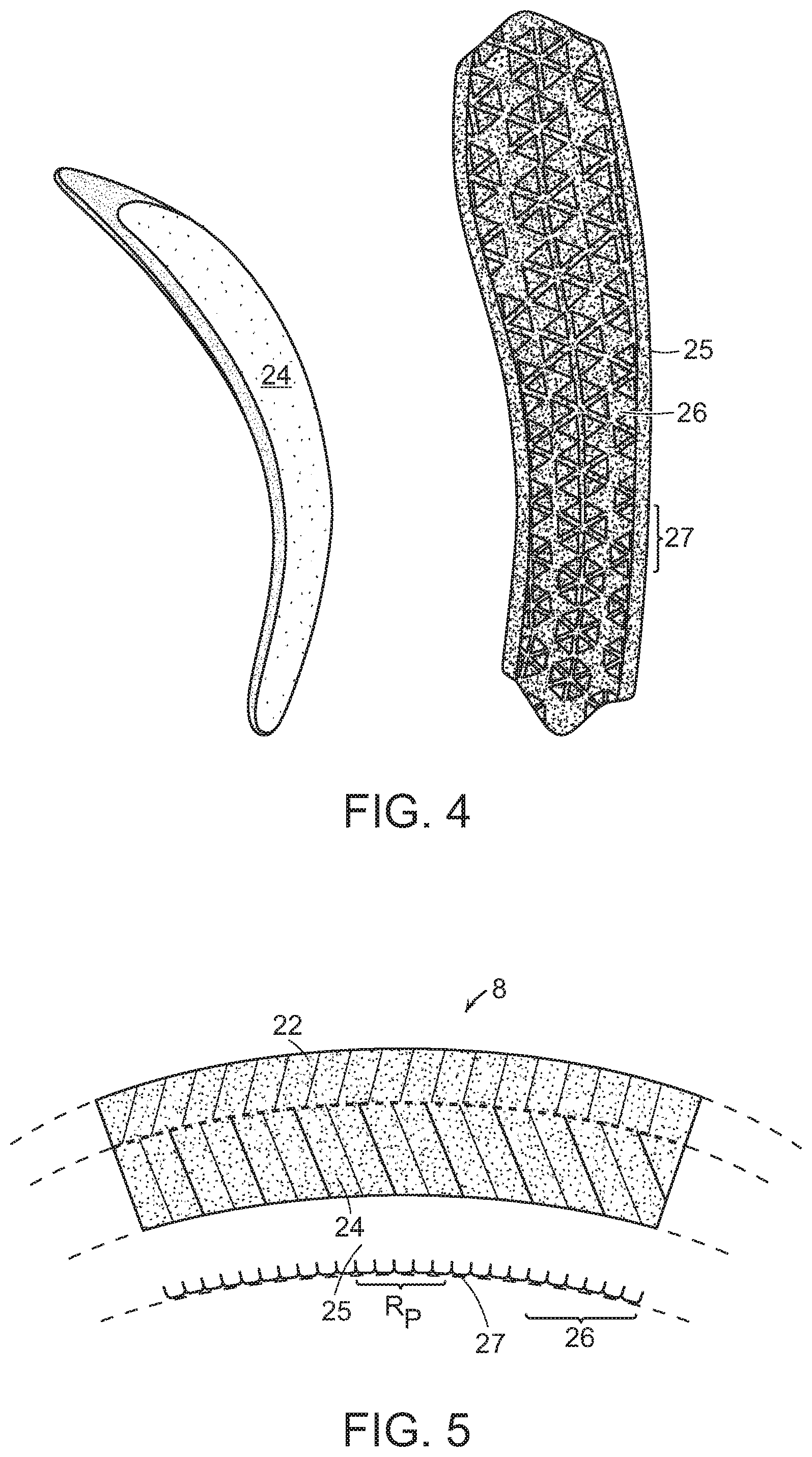
[0015] FIG. 4 is a close-up view of each of a support member and a gripping member that contains surface texturing in a predetermined pattern; and
[0016] FIG. 5 is a cross-section of a shoulder strap construction according to one embodiment of the invention.
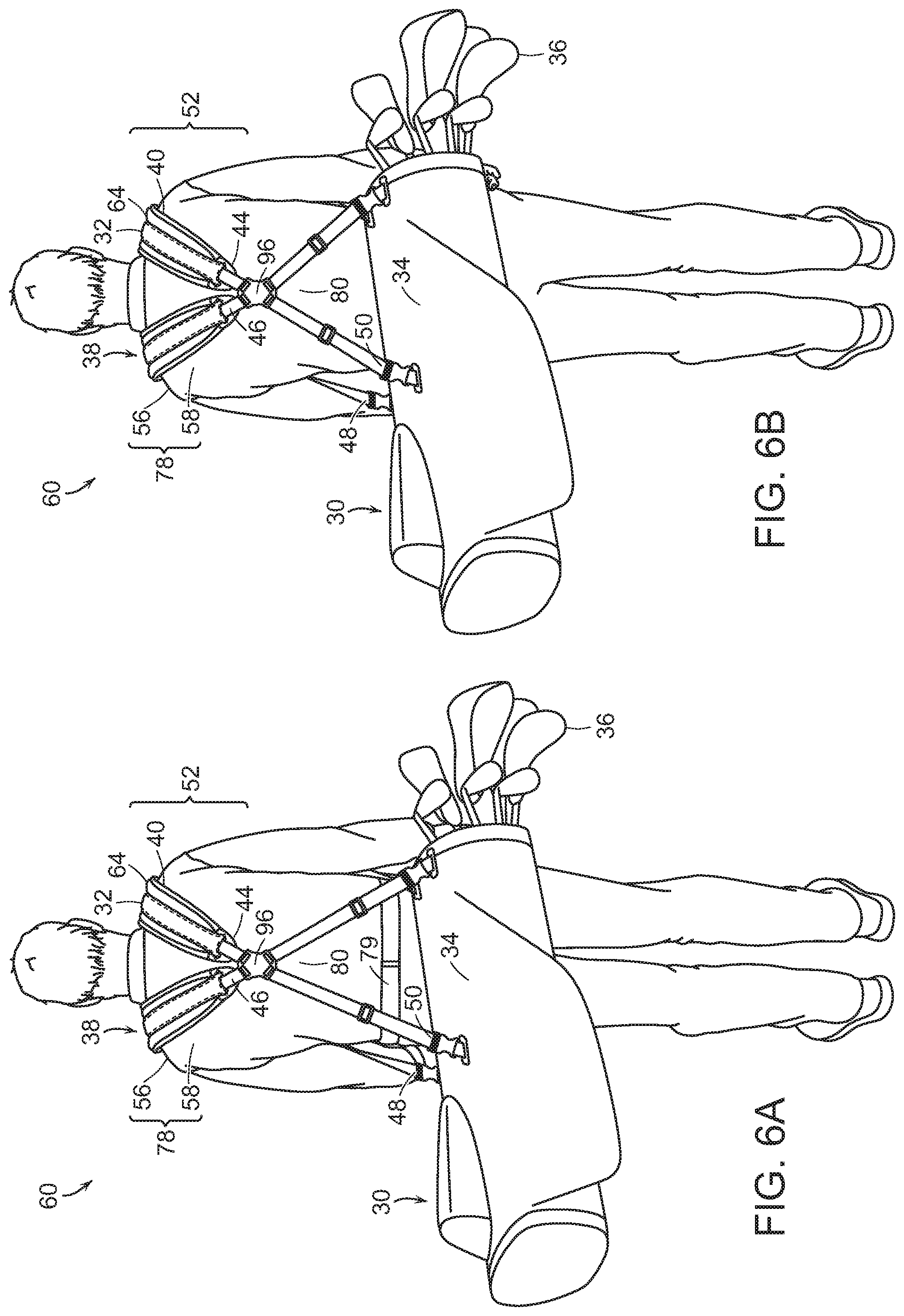
[0017] FIG. 6A is a rear perspective view of a golf bag and adjustable shoulder strap assembly of the invention mounted on a wearer before the pre-curved shoulder strap pad is positioned/adjusted in a predetermined location on a wearer's front, shoulder and back;
[0018] FIG. 6B is a rear perspective view of a golf bag and shoulder strap assembly of the invention mounted on a wearer after the pre-curved shoulder strap pad is positioned/adjusted in a predetermined location on a wearer's front, shoulder and back;
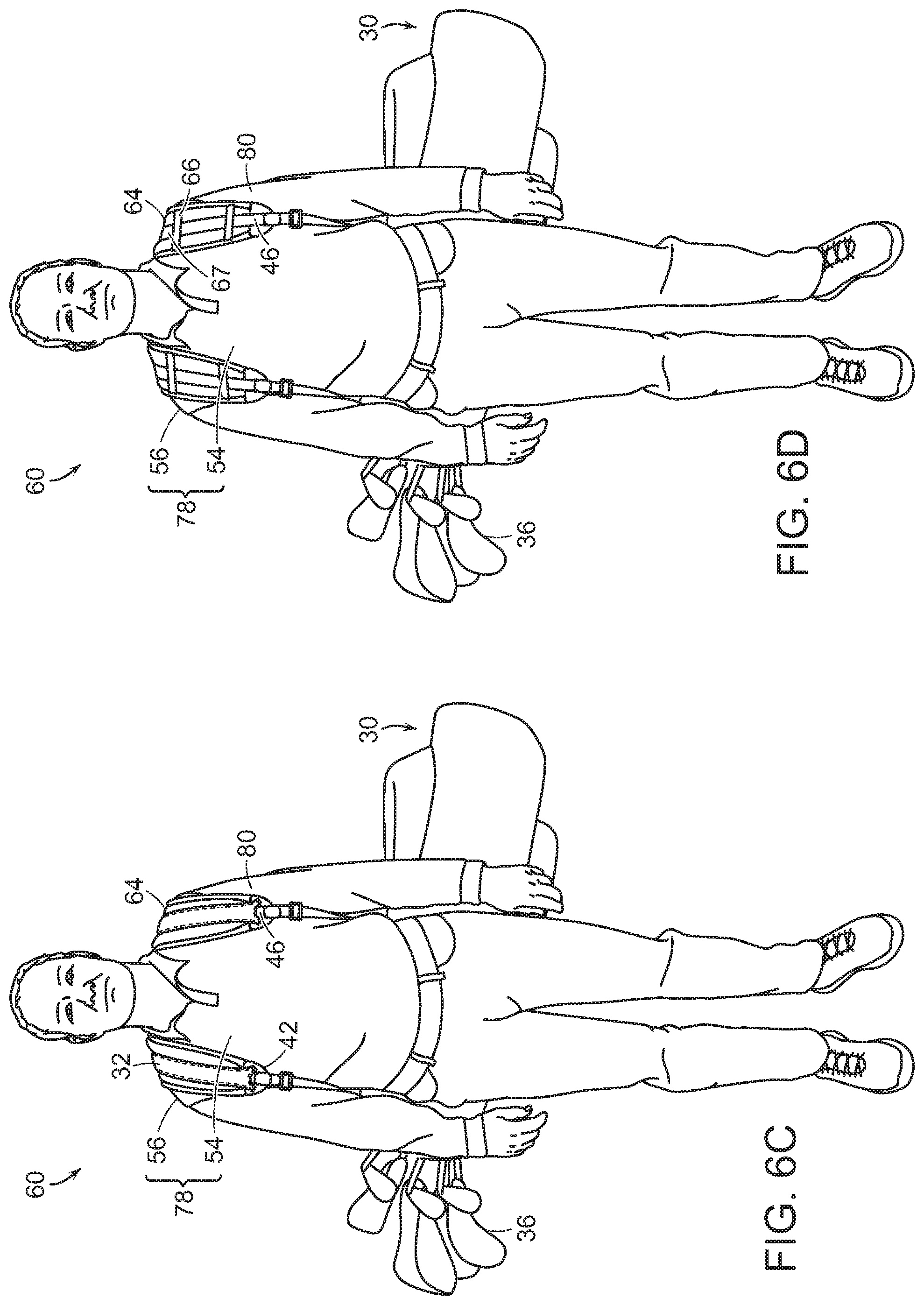
[0019] FIG. 6C is a front perspective view of a golf bag and shoulder strap assembly of the invention wherein an adjustable pre-curved shoulder strap pad according to one embodiment is mounted and positioned/adjusted in a predetermined location on a wearer's front, shoulder and back;
[0020] FIG. 6D is a front perspective view of a golf bag and shoulder strap assembly of the invention wherein an adjustable pre-curved shoulder strap pad according to a different embodiment than shown in FIG. 6C is mounted and positioned/adjusted in a predetermined location on a wearer's front, shoulder and back;
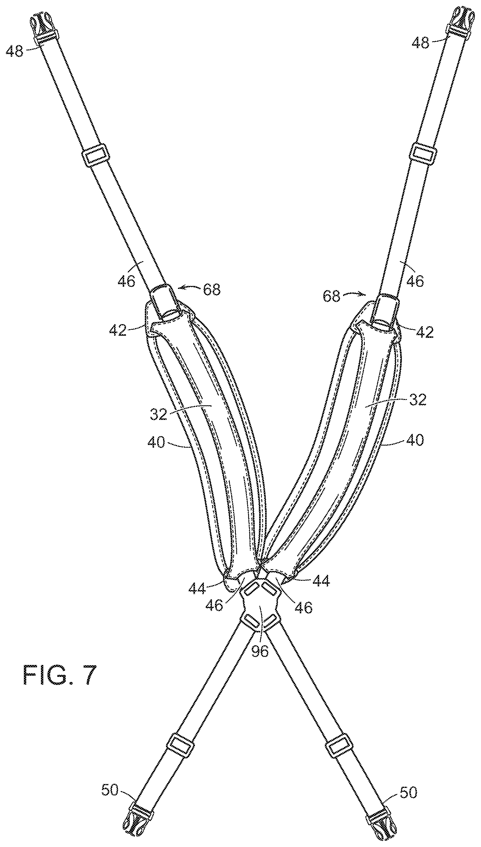
[0021] FIG. 7 is a close-up view of shoulder strap assembly according to one embodiment;
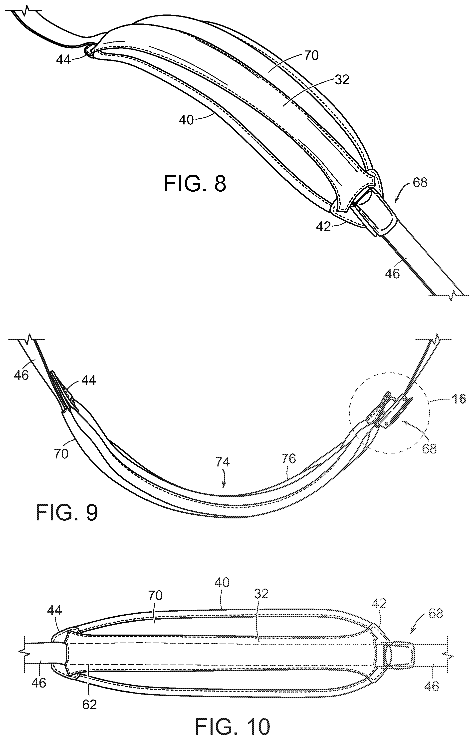
[0022] FIGS. 8-10 are elevated, side and top views, respectively, of a pre-curved shoulder strap pad according to one embodiment;
[0023] FIGS. 11-13 are elevated, side and top views, respectively, of a pre-curved shoulder strap pad according to a different embodiment than shown in FIGS. 8-10;
[0024] FIG. 14 depicts a pre-curved support member according to one embodiment that can be enclosed within a pre-curved shoulder strap pad of the invention, and
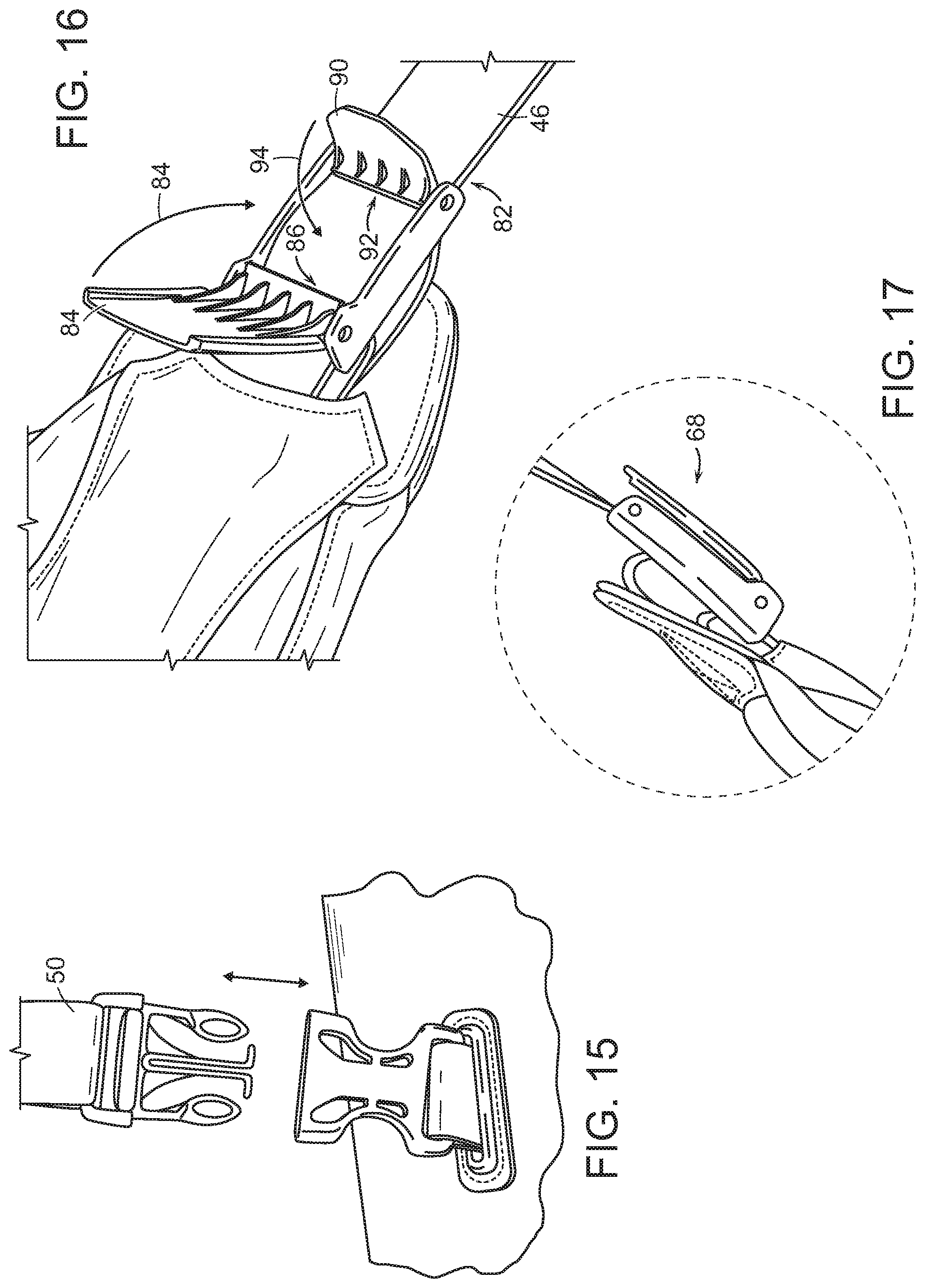
[0025] FIGS. 15-17 depict a buckle according to one embodiment that can be used to secure the strap in a desired position once the strap is adjusted into a predetermined location on a wearer's front, shoulder and back while the golf bag is mounted on a wearer.
SUMMARY OF THE INVENTION
[0026] Accordingly, in one embodiment, a golf bag has a shoulder strap, comprising: an elongated tubular body for holding golf clubs; and a shoulder strap assembly comprising a pre-curved strap pad, the pre-curved strap pad having a first end, a second end, and is configured to slidably receive a strap; wherein the strap has a first strap end and a second strap end, each which is attached to the elongated tubular body; such that the pre-curved strap pad is positioned in a predetermined location on a wearer's front, shoulder and back when the golf bag is mounted on the wearer.
[0027] The strap may be slidably received within an interior channel that extends within the pre-curved strap pad between the first end and the second end.
[0028] The strap may be slidably received within slots and/or tabs that are positioned along a top exterior portion of the pre-curved strap pad that does not contact the wearer's front, shoulder and back when the golf bag is mounted on the wearer.
[0029] The strap may thread each of the pre-curved strap pad and a buckle assembly.
[0030] The pre-curved strap pad may comprise a sheath and a pre-curved support member that is at least partially comprised of a silicon composition and is enclosed within the sheath.
[0031] The sheath may have an underside that contains surface texturing therein in a predetermined pattern that is configured to grip any surface that contacts the underside.
[0032] An underside of the pre-curved strap pad may have a contour that at least partially matches and follows a contour of the wearer's body when the pre-curved strap pad is positioned in the predetermined location on the wearer's front, shoulder and back.
[0033] The first end of the pre-curved strap pad may be tethered to the buckle assembly and the buckle assembly is operable with respect to each of the first end of the pre-curved strap pad and a portion of the strap that threads the buckle assembly to selectively adjust and set the position of the pre-curved strap pad into the predetermined location on the wearer's front, shoulder and back when the buckle assembly is in a closed position.
[0034] The buckle assembly may be in a closed position when i) a first clamping member of the buckle assembly is rotated toward and forced and secured against a first portion of the strap threading the buckle assembly from a first direction thereby forcing and securing the first portion of the strap threading the buckle assembly against the first end of the pre-curved strap pad within the buckle assembly; and ii) a second clamping member of the buckle assembly is rotated toward and forced and secured against a second portion of the strap threading the buckle assembly from a second direction, thereby forcing and securing the first portion of the strap threading the buckle assembly against a second portion of the first end of the pre-curved strap pad within the buckle assembly.
[0035] The shoulder strap assembly may comprise two pre-curved strap pads, two straps, and two buckle assemblies. Each strap may thread a hub. The hub may be disposed between the second end of each pre-curved strap pad and the second strap end of each strap and slidably receives each strap in a criss-cross configuration. The hub may be positioned on the wearer's back when the golf bag is mounted on the wearer.
[0036] The strap may be removably attached at least one end to the elongated tubular body.
[0037] The strap may be slidably adjusted within the pre-curved strap pad while mounted on the wearer without changing the predetermined location.
[0038] In a different embodiment, a golf bag of the invention comprises an elongated tubular body for holding golf clubs; and a shoulder strap assembly comprising: (i) a first strap having a first end and a second end; (ii) a second strap having a first end and a second end; and (ii) a bridge member having a first end and a second end. The first bridge member is disposed undetachably between the second end of the first strap and the second end of the second strap. Meanwhile, the elongated tubular body is configured to be detachably adjoined to each of the first end of the first strap, the first end of the second strap, the second end of the first strap and the second end of the second strap.
[0039] In one embodiment, the first strap comprises a first sheath, a first support member, and a first gripping layer; and the second strap comprises a second sheath, a second support member, and a second gripping member; wherein each sheath has a length L.sub.s; each support member has a length L.sub.su; and each gripping member has a length L.sub.g; wherein L.sub.g<L.sub.su<L.sub.s such that each of the first strap and the second strap has a predetermined radius R.sub.p.
[0040] In one embodiment, the bridge member, the first strap and the second strap are vertically coupled to form the shoulder strap assembly. In another embodiment, the bridge member, the first strap and the second strap are coupled horizontally to form the shoulder strap assembly.
[0041] In one embodiment, the bridge member comprises a flexible material.
[0042] In one embodiment, the first strap and the second strap are each flexibly adjoined to the elongated tubular body; and the first strap is flexibly adjoined to the second strap.
[0043] In one particular embodiment, the shoulder strap assembly is configured such that the second strap has a shape that is a reflection of the first strap's shape. In another embodiment, the first strap has a shape that differs from a shape of the second strap.
[0044] In one embodiment, at least one of the first strap sheath and the second strap sheath has an underside that contains surface texturing therein in a predetermined pattern that is configured to grip any surface that contacts the underside. In a specific such embodiment, the surface texturing is rubber-based.
[0045] In one embodiment, a golf bag of the invention comprises an elongated tubular body for holding golf clubs and a shoulder strap assembly comprising first and second straps; wherein a first section of each strap is configured to be adjacent a front of a wearer; a second section of each strap is configured to be adjacent a shoulder of the wearer; and a third section is configured to be adjacent to the wearer's back; and wherein the third section has a curve such that an upper portion of the third section extends vertically with respect to the wearer and a lower portion of the third section is horizontal with respect to the wearer.
[0046] A golf bag of the invention may comprise an elongated tubular body for holding golf clubs and a shoulder strap assembly, wherein the shoulder strap assembly comprises first and second straps; each strap having (i) a concave radius r.sub.cc extending from a first end of the strap to approximate a second end of the strap; and (ii) a convex radius r.sub.cv at the second end of the strap; wherein r.sub.cc>r.sub.cv.
DETAILED DESCRIPTION OF THE INVENTION
[0047] Advantageously, a golf bag of the invention includes a dual shoulder strap assembly which enables and facilitates mounting of both straps about the golfer's shoulders as well as improves continued distribution of the bag's weight across the golfer's back on the course and is meanwhile durable, possesses high mechanical strength, and is producible cost effectively within existing golf bag manufacturing processes. Collectively, FIG. 1A, FIG. 1B, and FIG. 1C depict rear perspective views of a person carrying a golf bag incorporating a dual shoulder strap assembly according to thr different constructions, and FIG. 1D depicts a frontal perspective views thereof. Golfer 1 carries golf bag 2 which comprises elongated tubular body 4 for holding golf clubs; as well as a dual shoulder strap assembly 6 that includes (i) a first strap 8, having a first end 10 and a second end 12; (ii) a second strap 14, having a first end 10 and a second end 12; and (iii) a bridge member 16 having a first end 18 and a second end 20.
[0048] Elongated tubular body 4 of golf bag 2 has a closed end 3 and an opposing open end 5, into which golf clubs 7 can be inserted into open end 5 of tubular body 4 (which has a cavity that is bordered by side walls (not shown)) of golf bag 2 such that, usually, golf club heads 9 with head covers 11 project from open end 5. The sidewall forming the cavity (not shown) within elongated tubular body 4 may include pockets and rings, and other compartments for golf balls, and accessories such as towels, hats, gloves, golf tees, beverages, and the like.
[0049] Elongated tubular body 4 can be made of any suitable textile material including leather, and woven/non-woven fabrics. Also, golf bag 2 may include a carrying handle and support leg assembly. The same or different fabric materials can be used to construct elongated tubular body 4, such as lightweight, high-strength fabrics and/or plastics. For example, woven fabrics made of nylon, polypropylene, or polyester, can be used. Elastic webbing made of spandex or rubber fabric material also can be used. The webbing normally is relatively thin and has minimal or no padding. Plastic, metal, composite, or other suitable material may be used as well.
[0050] In turn, FIG. 2A, FIG. 2B, and FIG. 2C are enlarged/close-up views of the dual shoulder strap assemblies 6 depicted collectively in FIG. 1A, FIG. 1B, and FIGS. 1C, and 1D respectively.
[0051] In each of these figures, bridge member 16 is disposed between and connecting the second ends 12 of first strap 8 and second strap 14 undetachably/unremovably/fixedly. Bridge member 16 is preferably formed from fabrics and/or compositions that are entirely or at least partially flexible, expandable, stretchable or otherwise pliable such as spandex or a rubber-containing fabric material. However, it is also envisioned that non-flexible fabrics and/or compositions may also be suitable materials for bridge member 16 such as an undetachable, non-removably attached plastic.
[0052] Meanwhile, elongated tubular body 4 of FIG. 1A, FIG. 1B, FIG. 1C and FIG. 1D is configured to be detachably adjoined/connected to first ends 10 and second ends 12 of each of first strap 8 and second strap 14 at connection mechanisms 13 and 15, respectively.
[0053] It is envisioned that first ends 10 and second ends 12 may be adjoined to elongated tubular body 4 either directly, or alternatively, indirectly by, for example, connecting straps 17 which are preferably undetachably/unremovably/fixedly attached to/ajoined with/to first ends 10 and second ends 12 yet detachably/removably attached/tethered to/ajoined with elongated tubular body 4 via attaching mechanisms 19 such as but not limited to sliders or other buckles, clips, clasps, hubs, pivots, eyehooks, loops, ties/knots, tri-glide clip, slide piece, or adjusting member that allows the shoulder strap to be adjusted lengthwise. Connecting straps 17 preferably have adjustable lengths.
[0054] In some embodiments, in lieu of attaching mechanisms 19, a bridge member such as bridge member 16 may be used to adjoin first ends 10 and second ends 12 to elongated tubular body 4 undetachably at both ends of each of straps 17. Any suitably shaped/constructed flexible or non-flexible or at least partially flexible bridge member may be used to adjoin first ends 10 and second ends 12 to elongated tubular body 4.
[0055] In one embodiment, as is represented in the cross-section of first strap 8 of FIG. 5, first strap 8 (as well as second strap 14, not shown) may be constructed so that sheath 22 is adjacent to support member 24, which in turn is adjacent to gripping member 25 (having an underside with surface texturing 26 thereon in a predetermined pattern 27 such as also depicted in FIG. 4); wherein sheath 22 has a length L.sub.s; support member 24 has a length L.sub.su; and gripping member 25 has a length L.sub.g; wherein L.sub.g<L.sub.su<L.sub.s such that each strap (first strap 8/second strap 14) has a predetermined radius R.sub.p. This construction can facilitate and improve how a strap 8 conforms to the wearer's shoulder. In a specific embodiment, surface texturing 26 in a predetermined pattern 27 may be formed of a rubber-based material.
[0056] In another embodiment, each strap comprises a sheath that encloses a support member which has a contour that is configured to be enclosed by the sheath. In this embodiment, the support member(s) are preferably flexible, curved, lightweight and relatively flat when not flexed or otherwise bent.
[0057] In one embodiment, bridge member 16, first strap 8 and the second strap 14 are coupled horizontally within shoulder strap assembly 6 such as in FIG. 1A. In another embodiment, bridge member 16, first strap 8 and second strap 14 are coupled vertically within shoulder strap assembly 6 such as in FIG. 1B and FIG. 1C. Other constructions are likewise envisioned, for example, wherein bridge member 16, first strap 8 and second strap 14 are coupled diagonally within shoulder strap assembly 6.
[0058] As used herein, the phrase "coupled vertically" means that the intersection of first end 18 (of bridge member 16) and second end 12 (of first strap 8) is vertically aligned with the intersection of second end 20 (of bridge member 16) and second end 12 (of second strap 14). Meanwhile, as used herein, the phrase "coupled horizontally" means that the intersection of first end 18 (of bridge member 16) and second end 12 (of first strap 8) is horizontally aligned with the intersection of second end 20 (of bridge member 16) and second end 12 (of second strap 14).
[0059] In one embodiment, first strap 8 and second strap 14 are each flexibly adjoined to elongated tubular body 4; and first strap 8 is flexibly adjoined to second strap 14.
[0060] In one particular embodiment, shoulder strap assembly 6 is configured such that second strap 14 has a shape that is a reflection of the shape of first strap 8. In another particular embodiment, shoulder strap assembly 6 is configured such that second strap 14 has a shape that is a partial reflection of the shape of first strap 8.
[0061] In yet another embodiment, shoulder strap assembly 6 is configured such that second strap 14 has a shape that is a translation of the shape of first strap 8. In still another embodiment, shoulder strap assembly 6 is configured such that second strap 14 has a shape that is a partial translation of the shape of first strap 8.
[0062] In alternative embodiments, first strap 8 has a shape that differs partially or in its entirety from the shape of second strap 14.
[0063] In particular embodiments, first strap 8 is shorter than second strap 14, which can facilitate a golfer's mounting and/or dismounting of the golf bag assembly by permitting one or more ends of first strap 8 to be released/disconnected from elongated body 4 before releasing one or more ends of second strap 14 so that the golf bag assembly can be slidably removed perhaps without even disconnecting second strap 14 from elongated body 4.
[0064] In one particular embodiment of a golf bag of the invention, shoulder strap assembly 6 comprises first strap 8 and second strap 14; wherein a first section of each strap is configured to be adjacent the wearer's front or chest area; a second section of each strap is configured to be adjacent or rest upon a shoulder of the wearer; and a third section of each strap is configured to be adjacent wearer's back; and wherein third section has a curve such that an upper portion of the third section extends vertically with respect to both the strap assembly and the wearer and a lower portion of the third section extends horizontally with respect to both the strap assembly and the wearer. It is envisioned that the lengths of each of the first, second and third sections can be pre-selected and coordinated considering torso measurement ranges for wearers or be customized according to match a particular wearer's torso measurements.
[0065] As emphasized on first strap 8 in FIG. 2A, first strap 8 and second strap 14 may each have (i) a concave radius r.sub.cc extending from first end 10 to approximate a second end 12; and (ii) a convex radius r.sub.cv at second end 12; wherein r.sub.cc>r.sub.cv.
[0066] It is envisioned that any of the constructions/shaped/contours of first strap 8 and second strap 14 discussed herein may be reversed, which may be of particular use for example when considering whether a person is left-handed or right-handed.
[0067] Any portion of shoulder straps 8 and 14 can have a cushioned portion made of any suitable material including, but not limited to, foams, natural and synthetic leathers, natural and synthetic rubbers, woven and non-wovens, and natural and synthetic fabrics. Foamed materials are particularly preferred for constructing the cushioned portions. These foamed materials have good stability and yet are also sufficiently flexible to make the cushioned portions comfortable when resting on the shoulders. These foamed materials can have a relatively soft durometer, for example, the hardness can be in the range of about 10 to about 80 Shore A. Another hardness scale (Asker.RTM.C) can be used to measure the indentation hardness of the foams, soft rubbers, elastomers or other materials, and the Asker C hardness is normally in the range of 25 to 75. In general, foam compositions are made by forming gas bubbles in a polymer mixture using a foaming (blowing) agent. As the bubbles form, the mixture expands and forms a foam composition having either an open or closed cellular structure. Many foams contain both open and closed cells. Various thermoplastic and thermoset materials may be used in forming the foam compositions as discussed further below. In one preferred embodiment, a polyurethane foam composition is used to form the foam material. In another embodiment, ethylene vinyl acetate (EVA) foams are used. In a particularly preferred embodiment, a high-stretch, high-recovery foam material referred to as AriaPrene.TM., and available from Tiong Long Corp. can be used. This foam material is hypo-allergenic, lightweight, non-toxic, and decomposable.
[0068] Other thermoplastic elastomers that can be used in accordance with this invention include polyester-polyether block copolymers such as Hytrel.RTM. resins, available from DuPont. These block copolymers are available in different grades and contain hard (crystalline) segments of polybutylene terephthalate and soft (amorphous) segments based on long-chain polyether glycols. Polyether-amide block copolymers, which are commonly known as Pebax.RTM. resins, and are available from Arkema, Inc. (Columbs, France), also may be used. Other suitable thermoplastic polymers include, but are not limited to, polyurethanes, polyureas, silicones, ethylene acid copolymer ionomers, polyesters, polyolefins, polyamides, polyamide-ethers, polyamide-esters; fluoropolymers, polystyrenes, polyvinyl chlorides, polycarbonates, polyethers, and polyimides including homopolymers, copolymers, and modified polymers and blends thereof.
[0069] Natural and synthetic rubber materials also may be used. Suitable rubber materials include, but are not limited to, polybutadiene, polyisoprene, ethylene propylene rubber ("EPR"), ethylene-propylene-diene ("EPDM") rubber, styrene-butadiene rubber, styrenic block copolymer rubbers (such as "SI", "SIS", "SB", "SBS", "SIBS", "SEBS", "SEPS" and the like, where "S" is styrene, "I" is isobutylene, "E" is ethylene, "P" is propylene, and "B" is butadiene), polyalkenamers such as, for example, polyoctenamer, butyl rubber, halobutyl rubber, polystyrene elastomers, polyethylene elastomers, polyurethane elastomers, polyurea elastomers, metallocene-catalyzed elastomers and plastomers, copolymers of isobutylene and p-alkylstyrene, halogenated copolymers of isobutylene and p-alkylstyrene, copolymers of butadiene with acrylonitrile, polychloroprene, alkyl acrylate rubber, chlorinated isoprene rubber, acrylonitrile chlorinated isoprene rubber, and blends of two or more thereof.
[0070] Advantageously, a golf bag and adjustable shoulder strap assembly of the invention desirably allows the wearer to optimize strap pad comfort and positioning on the wearer's front, shoulder and back while also facilitating golf bag positioning against the particular wearer. In a golf bag and adjustable shoulder strap assembly of the invention, a strap is slidably and adjustably received within a pre-curved strap pad and can be locked/secured into a desired position such that the pre-curved strap pad is located in a predetermined location on a wearer's front, shoulder and back when the golf bag is mounted on the wearer.
[0071] In this regard, FIGS. 6A, 6B, 6C, 6D, and 7-17 represent and depict several non-limiting embodiments of a golf bag and adjustable shoulder strap assembly of the invention. Generally, FIG. 6A and FIG. 6B are each rear perspective views of a golf bag and adjustable shoulder strap assembly of the invention, differing in that in FIG. 6A, the pre-curved strap pad has not been adjusted within the shoulder strap assembly (wearer 60's belt 79 is visible); whereas in FIG. 6B, the pre-curved strap pad has indeed been adjusted within the adjustable shoulder strap assembly (wearer 60's belt in not visible).
[0072] Meanwhile, FIG. 6C and FIG. 6D are each front perspective views of a golf bag and adjustable shoulder strap assembly of the invention, differing in that FIG. 6C depicts one pre-curved strap pad according to the invention, whereas FIG. 6D depicts a different pre-curved strap pad according to the invention.
[0073] FIG. 7 is a close-up view of one possible adjustable shoulder strap assembly of the invention. FIGS. 8-10 are elevated, side and top views, respectively, of a pre-curved strap pad according to one embodiment; and FIGS. 11-13 are elevated, side and top views, respectively, of a pre-curved strap pad according to a different embodiment than that depicted in FIGS. 8-10.
[0074] FIG. 14 represents one possible pre-curved support member that can be enclosed within a sheath portion of any pre-curved strap pad of the invention; and FIGS. 15-17 represent one possible securing means (a buckle) for securing the strap once it is secured to position in the pre-curved strap pad in a predetermined location on a wearer's front, shoulder and back when the golf bag is mounted on a wearer.
[0075] Now referring specifically to FIGS. 6A,6B, 6C, 6D, and/or 7-17 collectively, golf bag 30 has an elongated tubular body 34 for holding golf clubs 36; an adjustable shoulder strap assembly 38 comprising a pre-curved strap pad 40 having a first end 42, a second end 44, and being configured to slidably receive a strap 46 within an aperture portion 32 of pre-curved strap pad 40. Strap 46 has a first strap end 48 and a second strap end 50, each which is attached/connected to elongated tubular body 34 such that pre-curved strap pad 40 is positioned in a predetermined location 52 on a wearer 60's front 54, shoulder 56 and back 58 when golf bag 30 is mounted on wearer 60.
[0076] Strap 46 may be slidably received within an interior channel 62 that extends within pre-curved strap pad 40 between first end 42 and second strap end 44. In this embodiment, strap 46 is not visible when looking at top exterior portion 64 of pre-curved strap pad 40.
[0077] In alternative embodiments, as is shown in FIGS. 6D and 11-13, strap 46 may be slidably received within slots/tabs 66 that are positioned along top exterior portion 64 of pre-curved strap pad 40 such that at least segments 67 of strap 46 are visible when looking at top exterior portion 64.
[0078] In each of these embodiments, top exterior portion 64 of pre-curved strap pad 40 does not contact the wearer 60's front 54, shoulder 56 and back 58 when golf bag 30 is mounted on wearer 60.
[0079] Strap 46 threads each of the pre-curved strap pad 40 and buckle assembly 68.
[0080] Pre-curved strap pad 40 comprises a sheath 70 and a pre-curved support member 72 which can at least partially be comprised of a silicon composition and is enclosed within sheath 70. Sheath 70 has an underside 74 that can be configured to grip any surface that contacts the underside. Underside 74 has a pre-curved contour 76 that at least partially matches and follows a contour 78 of wearer 60's body 80 when pre-curved strap pad 40 is positioned in predetermined location 52 on wearer 60's front 54, shoulder 56 and back 58.
[0081] First end 42 of pre-curved strap pad 40 can be tethered to buckle assembly 68 which is operable with respect to each of first end 42 and a portion of strap 46 that threads buckle assembly 68 to selectively adjust and set pre-curved strap pad 40 into predetermined location/position 52 on the wearer 60's front 54, shoulder 56 and back 58 when buckle assembly 68 is in a closed position 82.
[0082] Buckle assembly 68 is in a closed position 82 when i) a first clamping member 84 of buckle assembly 68 is rotated toward and forced and secured against a first portion 86 of strap 46 threading buckle assembly 68 from a first direction 88 thereby forcing and securing the first portion 86 against first end 42 of pre-curved strap pad 40 within buckle assembly 68; and ii) a second clamping member 90 of buckle assembly 68 is rotated toward and forced and secured against second portion 92 of strap 46 threading buckle assembly 68 from second direction 94, thereby forcing and securing first portion 86 against second portion 92.
[0083] It is understood that buckle 68 represents one of several different securing mechanisms that can be utilized to set pre-curved strap pad 40 into predetermined location/position 52 on the wearer 60's front 54, shoulder 56 and back 58 when the securing mechanism is in a closed position.
[0084] The adjustable shoulder strap assembly may comprise two pre-curved strap pads 40, two straps 46, and two buckle assemblies 68. Each strap 46 threads a hub 96 which is disposed between second end 44 of each pre-curved strap pad and second strap end 50 of each strap 46 and slidably receives each strap 46 in a criss-cross configuration. Hub 96 is positioned on wearer 60's back 58 when golf bag 30 is mounted on wearer 60. Embodiments are indeed envisioned, however, wherein the adjustable shoulder strap assembly has a single pre-curved strap pad.
[0085] At least one end of strap 46 (first strap end 48 and/or second strap end 50) may be removably attached to elongated tubular body 34 such as with a clip.
[0086] Accordingly, pre-curved strap pad positioning and golf bag placement with respect to the wearer can be set and changed simply and easily by slidably adjusting the strap within the pre-curved strap pad. And desirably, golf bag positioning against the wearer can even be adjusted thereby without changing the position of the shoulder strap pad on the wearer's front, shoulder and back during that adjustment since the strap is slidably adjustable within and through the pre-curved strap pad.
[0087] When numerical lower limits and numerical upper limits are set forth herein, it is contemplated that any combination of these values may be used. Other than in the operating examples, or unless otherwise expressly specified, all of the numerical ranges, amounts, values and percentages such as those for amounts of materials and others in the specification may be read as if prefaced by the word "about" even though the term "about" may not expressly appear with the value, amount or range. Accordingly, unless indicated to the contrary, the numerical parameters set forth in the specification and attached claims are approximations that may vary depending upon the desired properties sought to be obtained by the present invention. All patents, publications, test procedures, and other references cited herein, including priority documents, are fully incorporated by reference to the extent such disclosure is not inconsistent with this invention and for all jurisdictions in which such incorporation is permitted. It is understood that the compositions, golf ball components, and finished golf balls described and illustrated herein represent only some embodiments of the invention. It is appreciated by those skilled in the art that various changes and additions can be made to compositions and products without departing from the spirit and scope of this invention. It is intended that all such embodiments be covered by the appended claims.
* * * * *
D00000
D00001
D00002
D00003
D00004
D00005
D00006
D00007
D00008
D00009
D00010
D00011
D00012
D00013
D00014

D00015

D00016
XML
uspto.report is an independent third-party trademark research tool that is not affiliated, endorsed, or sponsored by the United States Patent and Trademark Office (USPTO) or any other governmental organization. The information provided by uspto.report is based on publicly available data at the time of writing and is intended for informational purposes only.
While we strive to provide accurate and up-to-date information, we do not guarantee the accuracy, completeness, reliability, or suitability of the information displayed on this site. The use of this site is at your own risk. Any reliance you place on such information is therefore strictly at your own risk.
All official trademark data, including owner information, should be verified by visiting the official USPTO website at www.uspto.gov. This site is not intended to replace professional legal advice and should not be used as a substitute for consulting with a legal professional who is knowledgeable about trademark law.