Buckle And Buckle Male Part
ITO; Naoyuki ; et al.
U.S. patent application number 16/999253 was filed with the patent office on 2021-03-04 for buckle and buckle male part. This patent application is currently assigned to YKK CORPORATION. The applicant listed for this patent is YKK CORPORATION. Invention is credited to Naoyuki ITO, Ryoichiro TAKAZAKURA, Tomoko YAGAMI.
| Application Number | 20210059361 16/999253 |
| Document ID | / |
| Family ID | 1000005092749 |
| Filed Date | 2021-03-04 |


| United States Patent Application | 20210059361 |
| Kind Code | A1 |
| ITO; Naoyuki ; et al. | March 4, 2021 |
BUCKLE AND BUCKLE MALE PART
Abstract
A buckle may include male and female parts. In a case (A) where only the female part is attached to a slider of a slide fastener, the male part includes: a pair of arms respectively provided with locking protrusions; and a connecting rod connecting respective base ends of the pair of arms. The connecting rod is configured to curve away from a space between the locking protrusions of the arms when the arms are bent such that the locking protrusions approach one another. In a case (B) where the male part is attached to a slider of a slide fastener, the male part includes: a slider-holding frame configured to hold the slider; and a pair of arms that extend in the same direction from the slider-holding frame and are respectively provided with locking protrusions. The slider-holding frame includes a frame portion protruded into a space between the pair of arms toward a space between the locking protrusions.
| Inventors: | ITO; Naoyuki; (Toyama, JP) ; TAKAZAKURA; Ryoichiro; (Toyama, JP) ; YAGAMI; Tomoko; (Tokyo, JP) | ||||||||||
| Applicant: |
|
||||||||||
|---|---|---|---|---|---|---|---|---|---|---|---|
| Assignee: | YKK CORPORATION |
||||||||||
| Family ID: | 1000005092749 | ||||||||||
| Appl. No.: | 16/999253 | ||||||||||
| Filed: | August 21, 2020 |
| Current U.S. Class: | 1/1 |
| Current CPC Class: | A44B 11/2592 20130101; A44B 19/305 20130101 |
| International Class: | A44B 19/30 20060101 A44B019/30; A44B 11/25 20060101 A44B011/25 |
Foreign Application Data
| Date | Code | Application Number |
|---|---|---|
| Aug 27, 2019 | JP | 2019-155065 |
Claims
1. A buckle that comprises a female part and a male part which are coupled in separable manner, at least one of the female part and the male part being attached to a slider of a slide fastener, wherein in a case (A) where only the female part is attached to a slider of a slide fastener, the male part comprises: a pair of arms respectively provided with locking protrusions; and a connecting rod connecting respective base ends of the pair of arms, wherein the connecting rod is configured to curve away from a space between the locking protrusions of the arms when the arms are bent such that the locking protrusions approach one another; and in a case (B) where the male part is attached to a slider of a slide fastener, the male part comprises: a slider-holding frame configured to hold the slider; and a pair of arms that extend in the same direction from the slider-holding frame and are respectively provided with locking protrusions, wherein the slider-holding frame includes a frame portion protruded into a space between the pair of arms toward a space between the locking protrusions.
2. The buckle of claim 1, wherein the male part further comprises a resin-made spring that interconnects the arms.
3. The buckle of claim 2, wherein the resin-made spring is a belt-like portion that interconnects the locking protrusions of the arms.
4. The buckle of claim 3, wherein the resin-made spring comprises a pair of sloped belts respectively connected to the locking protrusions and a bottom belt extending to interconnect the sloped belts, and wherein an interspace between the pair of sloped belts gradually increases toward the bottom belt from said space between the locking protrusions.
5. The buckle of claim 2 wherein in the case of (A), the male part is configured as a closed loop-like member by a combination of the resin-made spring, the pair of arms, and the connecting rod.
6. The buckle of claim 1 wherein in the case of (A), the male part is attached, based on winding of a tape or a belt or a cord about the connecting rod, to an article to which the slide fastener is secured.
7. The buckle of claim 1 wherein in the case of (A), each of the arms comprises an arm main portion and an arm terminal portion, the arm terminal portion being connected to the connecting rod via the arm main portion and being provided with the locking protrusion.
8. The buckle of claim 7, wherein the maximum thickness of the connecting rod is less than the maximum thickness of the arm terminal portion provided with the locking protrusion.
9. The buckle of claim 7, wherein the arm main portion is a portion to be pushed by a person's finger, the thickness of the arm main portion being the greatest in the male part in the thickness direction of the buckle male part.
10. The buckle of claim 1 wherein in the case of (A), 0.3<(L79/W72)<2.5 is satisfied where L79 indicates a width of the connecting rod in the coupling direction of the female part and the male part, and W72 indicates a width of the arm in the width direction of the male part.
11. The buckle of claim 1 wherein in the case of (B), the slider-holding frame further comprises another frame portion that is connected to said frame portion to define an opening.
12. The buckle of claim 1 wherein in the case of (B), the slider-holding frame comprises a support connected to the frame portion via a hanging portion, the slider being sandwiched between the frame portion and the support.
13. The buckle of claim 12, wherein the support is shaped to partially match an outer profile of a top wing or a bottom wing of the slider.
14. The buckle of claim 1 wherein in the case of (B), the male part further comprises a resin-made spring interconnecting the arms, and the resin-made spring touches the slider-holding frame when the arms are bent to approach one another.
15. A buckle male part comprising: a pair of arms respectively provided with locking protrusions; and a connecting rod connecting respective base ends of the pair of arms, wherein the connecting rod is configured to curve away from a space between the locking protrusions of the arms when the arms are bent such that the locking protrusions approach one another.
16. A buckle male part comprising: a slider-holding frame configured to hold a slider of a slide fastener; and a pair of arms that extend in the same direction from the slider-holding frame and are respectively provided with locking protrusions, wherein the slider-holding frame includes a frame portion protruded into a space between the pair of arms toward a space between the locking protrusions.
17. The buckle male part of claim 15, further comprising a resin-made spring interconnecting the arms.
18. The buckle male part of claim 17, wherein the resin-made spring is a belt-like portion that interconnects the locking protrusions of the arms.
19. The buckle male part of claim 18, wherein the resin-made spring comprises a pair of sloped belts respectively connected to the locking protrusions and a bottom belt extending to interconnect the sloped belts, and wherein an interspace between the pair of sloped belts gradually increases toward the bottom belt from said space between the locking protrusions.
20. The buckle male part of claim 15, wherein 0.3<(L79/W72)<2.5 is satisfied where L79 indicates a width of the connecting rod in the coupling direction of the female part and the male part, and W72 indicates a width of the arm in the width direction of the male part.
Description
CROSS-REFERENCE TO RELATED APPLICATION
[0001] The present application claims a priority of Japanese Patent Application No. 2019-155065, filed on Aug. 27, 2019 and entitled "BUCKLE AND BUCKLE MALE PART", the entire content of which is hereby incorporated by reference.
TECHNICAL FIELD
[0002] The present disclosure is related to buckles and buckle male parts.
BACKGROUND
[0003] In common slide fasteners, one can easily open and close a slide fastener by pulling a pull tab of a slider. This is preferable from an aspect of convenience, but is fragile from an aspect of security. In this regard, European Patent No. 1300093 discloses a technique to integrally allocate a function of buckle male or female part to a slider of a slide fastener. Further, Japanese Patent No. 3034852 discloses that a locking member is coupled to a slider via a cord.
[0004] Also, various fastening members have been designed which are attachable to a slider body. For example, Japanese Patent Application Laid-open No. 2007-44535 discloses that a latch is attached to a slider body to enable coupling of sliders (See FIG. 7). Japanese Patent No. 4614140 discloses that a latch is attached to a bottom of a slider body (See FIG. 2). Japanese Patent No. 6035342 discloses a slider cover provided with an accommodating portion for accommodating a slider (See FIG. 1).
[0005] Note that Japanese Patent No. 5170889 discloses that, in a buckle having a male part in which an elastic portion is provided with a release-operation portion to be operated by person's fingers, the release-operation portion and an attachment portion for a belt-like-member are overlapped in the coupling direction of the male and female parts of the buckle (See FIG. 1).
SUMMARY
[0006] Newly recognized technical challenge is to reduce a length of buckle male part in a coupling direction of buckle male and female parts.
Solution to Problem
[0007] A buckle according to an aspect of the present disclosure may include a female part and a male part which are coupled in separable manner, at least one of the female part and the male part being attached to a slider of a slide fastener, wherein in a case (A) where only the female part is attached to a slider of a slide fastener, the male part comprises: a pair of arms respectively provided with locking protrusions; and a connecting rod connecting respective base ends of the pair of arms, wherein the connecting rod is configured to curve away from a space between the locking protrusions of the arms when the arms are bent such that the locking protrusions approach one another; and in a case (B) where the male part is attached to a slider of a slide fastener, the male part comprises: a slider-holding frame configured to hold the slider; and a pair of arms that extend in the same direction from the slider-holding frame and are respectively provided with locking protrusions, wherein the slider-holding frame includes a frame portion protruded into a space between the pair of arms toward a space between the locking protrusions.
[0008] In some embodiments, the male part further includes a resin-made spring that interconnects the arms. The resin-made spring may be a belt-like portion that interconnects the locking protrusions of the arms. The resin-made spring may include a pair of sloped belts respectively connected to the locking protrusions and a bottom belt extending to interconnect the sloped belts, and an interspace between the pair of sloped belts may gradually increase toward the bottom belt from said space between the locking protrusions.
[0009] In the case of (A), the male part may be configured as a closed loop-like member by a combination of the resin-made spring, the pair of arms, and the connecting rod. The male part may be attached, based on winding of a tape or a belt or a cord about the connecting rod, to an article to which the slide fastener is secured. Each of the arms may include an arm main portion and an arm terminal portion, the arm terminal portion being connected to the connecting rod via the arm main portion and being provided with the locking protrusion. Maximum thickness of the connecting rod may be less than Maximum thickness of the arm terminal portion provided with the locking protrusion. The arm main portion may be a portion to be pushed by a person's finger, the thickness of the arm main portion being the greatest in the male part in the thickness direction of the buckle male part. 0.3<(L79/W72)<2.5 may be satisfied where L79 indicates a width of the connecting rod in the coupling direction of the female part and the male part, and W72 indicates a width of the arm in the width direction of the male part.
[0010] In the case of (B), the slider-holding frame may further include another frame portion that is connected to said frame portion to define an opening. The slider-holding frame may include a support connected to the frame portion a via a hanging portion, the slider being sandwiched between the frame portion a and the support. The support may be shaped to partially match an outer profile of a top wing or a bottom wing of the slider. The male part may further include a resin-made spring interconnecting the arms, and the resin-made spring may touch the slider-holding frame when the arms are bent to approach one another.
[0011] A buckle male part according to an aspect of the present disclosure may include: a pair of arms respectively provided with locking protrusions; and a connecting rod connecting respective base ends of the pair of arms, wherein the connecting rod may be configured to curve away from a space between the locking protrusions of the arms when the arms are bent such that the locking protrusions approach one another.
[0012] A buckle male part according to an aspect of the present disclosure may include: a slider-holding frame configured to hold a slider of a slide fastener; and a pair of arms that extend in the same direction from the slider-holding frame and are respectively provided with locking protrusions, wherein the slider-holding frame may include a frame portion protruded into a space between the pair of arms toward a space between the locking protrusions.
[0013] The buckle male part described above may further include a resin-made spring interconnecting the arms. The resin-made spring may be a belt-like portion that interconnects the locking protrusions of the arms. The resin-made spring may include a pair of sloped belts respectively connected to the locking protrusions and a bottom belt extending to interconnect the sloped belts, and an interspace between the pair of sloped belts may gradually increase toward the bottom belt b from said space between the locking protrusions. 0.3<(L79/W72)<2.5 may be satisfied where L79 indicates a width of the connecting rod in the coupling direction of the female part and the male part, and W72 indicates a width of the arm in the width direction of the male part.
[0014] An aspect of the present disclosure may facilitate reduction of a length of buckle male part in a coupling direction of buckle male and female parts.
BRIEF DESCRIPTION OF DRAWINGS
[0015] Hereinafter, non-limiting embodiments and features of the present invention will be described with reference to FIGS. 1 to 18:
[0016] FIG. 1 is a schematic top view of a slide fastener to which a buckle for simple locking of a slide fastener according to a first embodiment is attached;
[0017] FIG. 2 is a schematic perspective view of a buckle in which buckle male and female parts are coupled;
[0018] FIG. 3 is a schematic perspective view of a buckle in which buckle male and female parts are separated;
[0019] FIG. 4 is a schematic top view of a buckle, schematically illustrating that locking protrusions of a buckle male part are locked by locking portions of a buckle female part;
[0020] FIG. 5 is a front-side view of a buckle female part;
[0021] FIG. 6 is a front-side view of a buckle male part;
[0022] FIG. 7 is a right-side view of a buckle female part;
[0023] FIG. 8 is a right-side view of a buckle male part;
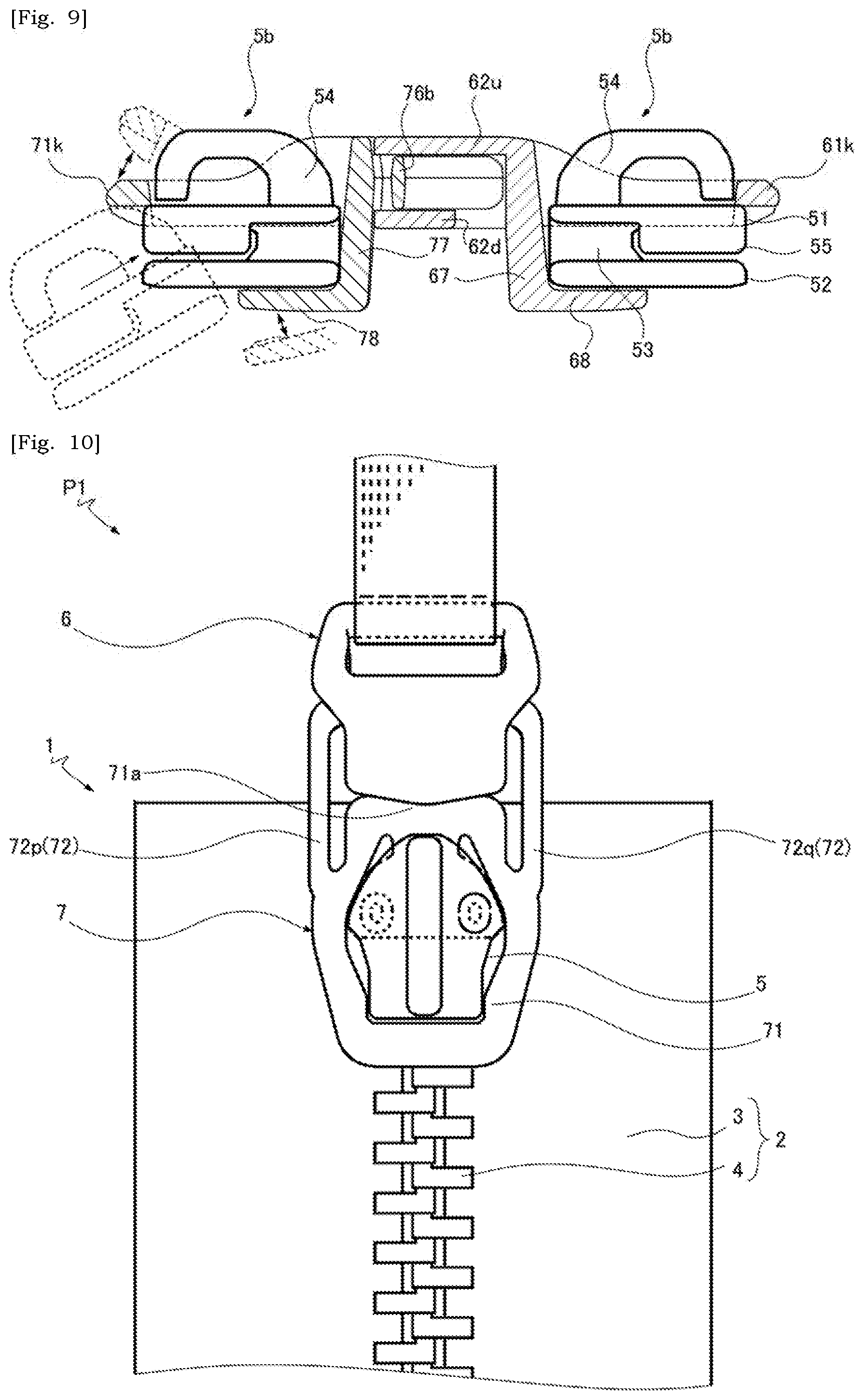
[0024] FIG. 9 is an illustration depicting that buckle male part and buckle female part are respectively attached to sliders;
[0025] FIG. 10 is a schematic partial view of an article to which a buckle of a second embodiment is attached, the buckle female part be provided with a belt-holding portion as an alternative to a slider-holding frame;
[0026] FIG. 11 is a schematic perspective view of a buckle in which buckle male and female parts are coupled;
[0027] FIG. 12 is a schematic center-cross-section of a buckle;
[0028] FIG. 13 is a schematic perspective view of a buckle of a third embodiment, only buckle female part is attached to a slider, and buckle male part is attached to an article to which a slide fastener is secured;
[0029] FIG. 14 is a schematic top view of a buckle male part;
[0030] FIG. 15 is a schematic rear-side view of a buckle male part;
[0031] FIG. 16 is a schematic center-cross-section of a buckle male part;
[0032] FIG. 17 is a schematic perspective view of a buckle of a fourth embodiment in which buckle male and female parts are separated; and
[0033] FIG. 18 is a schematic perspective view of a buckle in which buckle male and female parts are coupled.
DETAILED DESCRIPTION
[0034] A skilled person would be able to combine respective embodiments and/or respective features without requiring excess descriptions, and would appreciate synergistic effects of such combinations. Overlapping descriptions among the embodiments would be basically omitted. Referenced drawings are mainly for describing inventions, and may possibly be simplified for the sake of convenience of illustration. Individual features will be understood as a universal feature which is not only effective to buckles disclosed in the present specification but also effective to buckles not disclosed in the present specification.
[0035] Regarding a slide fastener or a buckle attached thereto, Front-Rear direction is understood based on movement of a slider. Front-side matches a direction in which a slider moves to close a slide fastener (to couple fastener stringers). Rear-side matches a direction in which a slider moves to open a slide fastener (to separate fastener stringers). Left-Right direction is orthogonal to Front-Rear direction and is parallel to a tape surface of a fastener tape. UP-Down direction is orthogonal to Front-Rear direction and is orthogonal to a tape surface of a fastener tape. Slide fastener 1 illustrated in FIG. 1 includes two sliders 5a,5b, and different standards regarding directions will be applied to the respective sliders 5a,5b. Front-side of the slider 5a is opposite to front-side of the slider 5b. Regarding double-headed-arrows in FIG. 1, F indicates a front-side, Re indicates a rear-side, L indicates a left-side, and Ri indicates a right-side.
[0036] Structures of a buckle can be described with reference to directions based on a buckle without referring to the above-defined slider-based directions. As would be appreciated from the following descriptions, embodiments are envisioned in which not only a buckle is used together with a slide fastener but also a buckle is independently used without a slide fastener. In particular, a reference may be made to a coupling direction of female and male parts in a buckle. The coupling direction matches a direction a female part and/or a male part are/is moved for coupling the female and male parts (Note that, the coupling direction is parallel to the above-described front-rear direction based on a slider). Width direction and Thickness direction orthogonal to Coupling direction will be referred. Width direction is a direction in which a pair of arms are apposed. Thickness direction is orthogonal to Coupling direction and Width direction.
THE 1.sup.ST EMBODIMENT
[0037] First embodiment will be described with reference to FIGS. 1 to 9. Slide fastener 1 is attached to a container such as a bag for example and enables opening and closing of the container. Slide fastener 1 has a pair of left and right fastener stringers 2 and two sliders 5a,5b (totally 5) for opening and closing the slide fastener 1 (for coupling and separating the stringers). The number of slider included in the slide fastener 1 should not be limited to 2, and embodiments are envisioned where one or three or three or more sliders are included. Each fastener stringer 2 has a fastener tape 3 the thickness of which is defined by upper and lower tape surfaces, and a fastener element 4 attached to a side-edge of the fastener tape 3.
[0038] The fastener tape 3 is a woven fabric or knitted fabric or combination thereof with sufficient flexibility. The fastener element 4 is a metal element or a resin element or a coil element in which monofilament is helically wound. Attachment of the fastener element 4 to the fastener tape 3 will be appropriately done in accordance with a type of element. In cases of metal elements, the elements are swaged and attached to the side-edge of the fastener tape 3. In cases of resin elements, the elements are attached to the fastener tape 3 through insert-molding. In cases of coil element, the coil element is sewn to the fastener tape 3. The slider 5 may be made of resin, metal or ceramics.
[0039] The slider 5 has a top wing 51, a bottom wing 52, a coupling pillar 53 for coupling these wings, a pull-attachment column 54 and flanges 55 (See FIGS. 1 and 9). Illustration of a pull tab attached to the pull-attachment column 54 is omitted. The top wing 51 and the bottom wing 52 are opposed, and a passage for the fastener elements 4 is defined in the up-down direction. Left and right flanges 55 are opposed, and the passage for the fastener elements 4 is restricted in the left-right direction. The coupling pillar 53 is provided in the center of the left-right direction at the front end of the top wing 51. A pair of left and right front mouths are arranged to sandwich the coupling pillar 53, and the respective left and right fastener elements 4 move into and out from the slider 5 there-through. One rear mouth is provided at the opposite side of the left and right mouths, and the (engaged) left and right fastener elements 4 moves into and out from the slider 5 there-through.
[0040] Buckle for simple/temporal locking of a slide fastener (hereinafter simply referred to as a buckle) 100 is used to arrest the respective sliders 5a,5b of the slide fastener 1. The buckle 100 includes a female part 6 and a male part 7 which are coupled in separable manner. Each of the female part 6 and the male part 7 is attached to the slider 5a,5b. As long as the female part 6 and the male part 7 are coupled, the slider 5a,5b cannot move individually and freely. Separating the left and right fastener stringers 2 is hindered, thus enhancing the security of an article to which the slide fastener 1 is secured. Note that, the buckle 100 of the present disclosure can be used not only to keep the slide fastener 1 closed but also to keep the slide fastener 1 open. Furthermore, embodiments are envisioned where one or both of the male and female parts 7 and 6 are not attached to the slider 5 of the slide fastener 1.
[0041] Hereinafter, a configuration of the buckle 100 will be described in detail. Each of the female part 6 and the male part 7 can be made of resin (e.g. Polyacetal, Nylon, Polypropylene, Elastomer, and Polycarbonate) and can be produced through injection-molding. The male part 7 has a slider-holding frame 71 configured to hold the slider 5, a pair of arm 72p,72q (totally 72) that extend in the same direction from the slider-holding frame 71 and are respectively provided with locking protrusion 73p,73q (totally 73), and a resin-made spring 76 that interconnects the arms 72. The female part 6 has a slider-holding frame 61 and an arm-receiving portion 62 that is connected to the slider-holding frame 61. The locking protrusion 73 is a portion to be locked by a locking portion 63 of the female part 6 when the male part 7 and female part 6 are fully coupled.
[0042] The slider-holding frame 71 of the male part 7 has a frame body 71f configured to hold the top wing 51 or the bottom wing 52 of the slider 5, and a support 78 connected to the frame body 71f via a hanging portion 77. In common sliders, a pull-attachment column is arranged onto the top surface of the top wing, making the top surface of the top wing uneven. In common sliders, the bottom surface of the bottom wing is a flat surface. Therefore, in cases where the slider-holding frame 71 is provided with the support 78, the frame body 71f is typically configured to hold the top wing of the slider. However, the frame body 71f can be configured to hold the bottom wing 52 of the slider 5.
[0043] The frame body 71f is sectioned into a frame portion (first frame portion) 71a and a frame portion (second frame portion) 71b in the coupling direction of the female part 6 and the male part 7. The frame portion 71b is connected to the frame portion 71a to define an opening. Base end 72r of the arm 72 is connected to a portion at which the frame portion 71a and the frame portion 71b are connected. The frame portion 71a extends in C-shape or U-shape between the base end 72r of one arm 72 and the base end 72r of the other arm 72. Similarly, the frame portion 71b extends in C-shape or U-shape between the base end 72r of one arm 72 and the base end 72r of the other arm 72. In the coupling direction of the female part 6 and the male part 7, the length L1 of the frame portion 71a is less than the length L2 of the frame portion 71b (See FIG. 4). Interference between the arm 72 and the frame portion 71a when the arm 72 pivots may be suppressed by shortening the range, in which the arm 72 and the frame portion 71a are overlapped, in the coupling direction of the female part 6 and the male part 7.
[0044] In the present embodiment, the frame portion 71a protrudes into a space between the arms 72p,72q toward the space SP73 between the locking protrusions 73p,73q. This allows reduction of the length L0 (See FIG. 4) of the male part 7 in the coupling direction of the female part 6 and the male part 7. Slits SL1,SL2 are formed between the arm 72 and the frame portion 71a, thus avoiding the interference between the arm 72 and the frame portion 71a.
[0045] The frame body 71f has a pair of side portions 71c,71d to which the base end 72r of the arm 72 is connected, a wall 71j that extends in the width direction of the male part 7 to interconnect ends of the side portions 71c,71d, and a bar 71k that extends in the width direction of the male part 7 to interconnects the other ends of the side portions 71c,71d. The side portions 71c,71d extend along the left-side and right-side edges of the slider 5 to be adapted for holding the slider 5. Interspace between the side portions 71c,71d in the width direction of the male part 7 gradually increases and then gradually decreases as the side portions 71c,71d extend away from the wall 71j. The point of this transition of the interspace may correspond to the front end of the flange 55 of the slider 5.
[0046] Bulged portion 71z may be provided which reduces a width of the opening of the slider-holding frame 71 (the frame body 71f) in the width direction of the male part 7. This allows that the top wing 51 or the bottom wing 52 of the slider 5 is securely held by the slider-holding frame 71 (the frame body 71f). Note that the frame body 71f is not necessarily a closed frame. The frame body 71f may be a frame with a partial cutout. For example, the bar 71k is omitted and the frame body 71f is U-shaped.
[0047] Slider 5 is held between the frame body 71f and the support 78. The support 78 is shaped to partially match an outer profile of the top wing 51 or the bottom wing 52 of the slider 5, thus the support 78 can have no projection from the slider 5. Typically, the support 78 is shaped to match the front-half of the outer profile of the top wing 51 or the bottom wing 52. The support 78 may be arranged inwardly of the inner edge of the slider-holding frame 71 (See FIG. 3). In this case, the slider-holding frame 71 and the support 78 are not overlapped in the thickness direction of the male part 7. One or more bosses 78p configured to contact the slider 5 (e.g. the bottom surface of the bottom wing 52) can be provided onto the support 78. Preferably, the boss 78p is arranged closer to the free end of the support 78 which is opposite to the connecting end of the support 78 with the hanging portion 77. This allows that the slider 5 is more securely held between the frame body 71f and the support 78.
[0048] Attachment of the male part 7 to the slider 5 is possible as schematically shown in FIG. 9 by pushing the slider 5 into a space between the bar 71k and the support 78 which is accompanied by increase and decrease of distance between the bar 71k and the support 78. It is adequate that at least one of the bar 71k and the support 78 is displaced. In some cases, the support 78 pivots about a connecting end of the hanging portion 77 connected to the wall 71j. Embodiments are envisioned where the hanging portion 77 and the support 78 may be omitted and the slider 5 is held by the frame body 71f only.
[0049] The arm 72p,72q has a base end 72r connected to the boundary between the frame portion 71a and the frame portion 71b, and the arm 72p,72q extend in the same direction from the base ends 72r away from the slider-holding frame 71 in the coupling direction of the female part 6 and the male part 7. The arm 72p,72q can be bent about its base end 72r inwardly in the width direction, allowing the locking protrusions 73 of the arms 72p,72q to approach one another. Note that, inner-side in the width direction is a direction directed to a center line CL1 (See FIG. 4) regarding the width direction of the male part 7. Outer-side in the width direction is a direction directed away from the center line CL1 (See FIG. 4) regarding the width direction of the male part 7. The arm 72 can be bent inward in the width direction in accordance with external force and, when the external force is released, can move outward in the width direction back to the initial posture. When viewed from above as shown in FIG. 4, the left arm 72p can pivot clockwise to the right side about its base end 72r. The right arm 72q can pivot counterclockwise to the left side about its base end 72r.
[0050] The arm 72p,72q has an arm main portion 72m extending in the coupling direction of the female part 6 and the male part 7, and an arm terminal portion 72n connected to the slider-holding frame 71 via the arm main portion 72m and provided with the locking protrusion 73. The arm main portion 72m linearly extends away from the slider-holding frame 71 in the coupling direction of the female part 6 and the male part 7. The arm terminal portion 72n extends in an arc inward in the width direction toward the other arm 72 (e.g. its locking protrusion 73) of the pair. The locking protrusion 73 is provided at the inner end of the arm terminal portion 72n, but its location should not be limited to this. In cases where the locking protrusions 73 are arranged adjacently (apposed) with a predetermined space SP73, it is facilitated that the width of the arm-receiving portion 62 of the female part 6 is reduced (See FIG. 5). The locking protrusion 73 protrudes from the arm terminal portion 72n in the opposite directions (i.e. upward and downward) in the thickness direction of the male part 7 (See FIG. 6). Note that, embodiments are envisioned where the locking protrusion 73 protrudes only one side in the UP-Down direction.
[0051] The arm main portion 72m is pushed by a person's finger to operate the posture of the arm 72. The arm main portion 72m is pushed inward in the width direction so that the arm 72 is bent inward in the width direction and the locking protrusion 73 of the arm terminal portion 72n moves inward in the width direction. The arm main portion 72m is a flat belt-like portion having a small width in the width direction of the male part 7 and having a greater thickness in the thickness direction of the male part 7 (compared with the width). In other words, the arm main portion 72m has a thin thickness in the width direction of the male part 7 and a wide width in the thickness direction of the male part 7. In cases where the thickness of the arm main portion 72m in the thickness direction of the male part 7 is the maximum in the male part 7, it is possible to provide a widen contact area for a person's finger. Note that, in the thickness direction of the male part 7, the thickness of the arm main portion 72m is greater than the thicknesses of the arm terminal portion 72n and the locking protrusion 73.
[0052] Slits SL1,SL2 are formed between the arm main portion 72m and the frame portion 71a, allowing the arm 72 to be bent about the base end 72r inward in the width direction. The slits SL1,SL2 extend along the coupling direction of the female part 6 and the male part 7 with a substantially constant lateral width. Space allowing the resin-made spring 76 to be arranged therein is formed between the arm terminal portion 72n and the frame portion 71a.
[0053] In the arms 72p,72q, when the arm 72 is not deformed, 0.degree.<.theta.<80.degree. is satisfied where .theta. indicates an angle between an axial line AX1 matching the extending direction of the arm main portion 72m and an axial line AX2 extending between the base end 72r of the arm 72 and the locking protrusion 73. The locking protrusions 73 are arranged adjacently with a given space SP73, facilitating that the width of the arm-receiving portion 62 of the female part 6 is reduced.
[0054] Width of the space SP73 between the locking protrusions 73p,73q is variable. When the arm main portions 72m are pushed inward in the width direction such that the locking protrusions 73 approach one another for the male part 7 to be coupled to or decoupled from the female part 6, the width of the space SP73 in the width direction of the male part 7 is reduced. In cases where the resin-made spring 76 is provided, the resin-made spring 76 and the slider-holding frame 71 touch one another and the width of the space SP73 may be hindered to be smaller. However, the width of the space SP73 may be further smaller if the resin-made spring 76 deforms. Note that, if the resin-made spring 76 and the slider-holding frame 71 contact one another, the arm 72 may be prevented from being bent excessively. It is not a requisite that the resin-made spring 76 touches the slider-holding frame 71 in a process of coupling of the female part 6 and the male part 7.
[0055] The resin-made spring 76 may be a belt-like portion that interconnects the respective locking protrusions 73 of the arms 72. A closed loop is formed by the combination of the resin-made spring 76, the arm 72p,72q, and the slider-holding frame 71, improving the mechanical strength of the male part 7. For example, in cases where the resin-made spring 76 is not provided, there may be a possibility that a foreign body enters a space between the arms 72p,72q to destroy the arms 72. Such a problem may be avoided or suppressed in cases where the arms 72p,72q are connected by the resin-made spring 76.
[0056] The resin-made spring 76 has a pair of sloped belts 76p,76q which are respectively coupled to the locking protrusions 73 of the arms 72 and a bottom belt 76b that extends to interconnect the sloped belts 76p,76q. Distance between the pair of sloped belts 76p,76q gradually increases toward the bottom belt 76b from the space SP73 between the locking protrusions 73p,73q. In some cases, when the arms 72 are bent such that the locking protrusions 73 approach one another for the male part 7 to be coupled to or decoupled from the female part 6, the resin-made spring 76 and the slider-holding frame 71 are brought into contact one another. This is a result of reduced length of the male part 7 in the coupling direction of the female part 6 and the male part 7.
[0057] The resin-made spring 76 (e.g. the bottom belt 76b) and the frame portion 71a have complementary opposed surfaces f1, f2 (See FIG. 4). The opposed surface f1 has a pair of sloped surfaces which are arranged adjacently to shape a protrusion on the center line CL1 of the male part 7. The opposed surface f2 has a pair of sloped surfaces which are arranged adjacently to shape a recess on the center line CL1 of the male part 7. This allows that a movable range for the resin-made spring 76, in turn for the locking protrusions 73 is widened. Additionally or alternatively, this allows that a force is set within an appropriate range which is required for coupling the male part 7 and the female part 6. Note that, in some cases, deformation of the resin-made spring 76 allows the locking protrusions 73 of the arms 72 to be in contact one another.
[0058] Position and direction of protruding of the locking protrusion 73 of the arm 72 would be various and should not be limited to the illustrated examples. The locking protrusion 73 may protrude not in the thickness direction of the male part 7, but in the width direction of the male part 7. For example, a left locking protrusion 73 may be arranged to protrude leftward from the left-side surface of the left arm 72p. Right locking protrusion 73 may be arranged to protrude rightward from the right-side surface of the right arm 72q. In such cases, a resin portion of the male part 7 may be arranged in the space SP73 between the locking protrusions 73p,73q but there is still a space SP73 between the locking protrusions 73.
[0059] As described above, the female part 6 has a slider-holding frame 61 and an arm-receiving portion 62 connected to the slider-holding frame 61. Likewise the slider-holding frame 71 of the male part 7, the slider-holding frame 61 has a frame body 61f configured to hold the top wing 51 or the bottom wing 52 of the slider 5, and a support 68 connected to the frame body 61f via a hanging portion 67 The frame body 61f has a pair of side portions 61c,61d, a wall 61j extending in the width direction of the female part 6 to interconnect one ends of the side portions 61c,61d, and a bar 61k extending in the width direction of the female part 6 to interconnect the other ends of the side portions 61c,61d.
[0060] The side portions 61c,61d extend along the left-side and right-side edges of the slider 5 so as to be adapted for holding the slider 5. Interspace between the side portions 61c,61d in the width direction of the female part 6 gradually increase and then gradually decrease as the side portions 61c,61d extending away from the wall 61j. The point of this transition of the interspace may correspond to the front end of the flange 55 of the slider 5. Note that, the frame body 61f is not necessarily limited to a closed frame. The frame body 61f may be a frame with partial cutout. For example, the bar 61k is omitted, and the frame body 61f is U-shaped.
[0061] Likewise the male part 7, the slider 5 is sandwiched and held between the frame body 61f and the support 68 in the female part 6. Description made for the frame body 71f and the support 78 of the male part 7 holds true for the frame body 61f and the support 68 of the female part 6 and thus overlapping descriptions are omitted. Note that, in the slide fastener 1, the supports 78,68 of the male part 7 and the female part 6 extend in the opposite directions, respectively, from the hanging portions 77,67 of the male part 7 and the female part 6 (See FIGS. 7-9).
[0062] The arm-receiving portion 62 has a pair of plates i.e. top plate and bottom plate 62u,62d which are arranged to face one another in the thickness direction of the female part 6. The top and bottom plates 62u,62d extend substantially in parallel in the same direction (along the coupling direction of the female part 6 and the male part 7) from the wall 61j of the slider-holding frame 61. Receiving space 62m for receiving the arms 72 is formed by the top and bottom plates 62u,62d. The receiving space 62m has a main opening 62m1 between ends of the top and bottom plates 62u,62d, and left-side and right-side openings 52m2 between edges (at the same side) of the top and bottom plates 62u,62d (See FIG. 3).
[0063] The opposed surfaces of the top and bottom plates 62u,62d are respectively provided with a pair of locking portions 63p,63q (totally 63) (See FIGS. 4 and 5). The locking portions 63p,63q are arranged with an interspace in the width direction of the female part 6. Each locking portion 63p,63q has a guide surface 63a, and a locking surface 63b positioned farther away from the main opening 62m1 than the guide surface 63a, and an intermediate surface 63c between the guide surface 63a and the locking surface 63b. The guide surfaces 63a of the locking portions 63p,63q approach one another as being away from the main opening 62m1 (e.g. toward the wall 61j of the slider-holding frame 61).
[0064] When the male part 7 is moved toward the female part 6 to be coupled with the female part 6, the locking protrusions 73 of the arms 72 touch the guide surfaces 63a of the locking portions 63. When the locking protrusion 73 moves on the guide surface 63a away from the main opening 62m1 of the arm-receiving portion 62, the locking protrusion 73 is gradually displaced inward in the width direction toward the center line CL1 of the male part 7. Accordingly, the space SP73 between the locking protrusions 73p,73q is reduced. After the locking protrusion 73 passes the guide surface 63a and passes the intermediate surface 63c, the locking protrusion 73 can move outward in the width direction of the buckle 100. The space SP73 between the locking protrusions 73 in the width direction of the buckle 100 increases, and the locking protrusion 73 and the locking surface 63b are brought into contact and/or face one another. Even when the male part 7 is moved away from the female part 6, the male part 7 cannot be separated from the female part 6 as the locking protrusion 73 is in contact with the locking surface 63b of the locking portion 63.
THE 2.sup.ND EMBODIMENT
[0065] Second embodiment will be described with reference to FIGS. 10 to 12. As would be understood from FIG. 10, only the male part 7 is attached to the slider 5 of the slide fastener 1. The female part 6 is not attached to a slider of the slide fastener 1, but is attached, via a tape or a belt or a cord, to an article P1 to which the slide fastener 1 is secured. Likewise the first embodiment, in the present embodiment, the frame portion 71a protrudes into a space between the pair of arms 72p,72q toward the space SP73 between the locking protrusions 73p,73q in the male part 7. This allows reduction of a length of the male part 7 in the coupling direction of the female part 6 and the male part 7.
[0066] As would be understood from FIGS. 11 and 12, the structure of the male part 7 is the same as that described in the first embodiment. The female part 6 has an attachment portion 65 for a belt or a tape, as an alternative of the slider-holding frame 61. The attachment portion 65 has a beam 65m, and a pair of left and right supports 65p,65q which supports the respective ends of the beam 65m. The top plate 62u and the bottom plate 62d are connected to the supports 65p,65q.
THE 3.sup.RD EMBODIMENT
[0067] Third embodiment will be described with reference to FIGS. 13 to 16. As would be understood from FIG. 13, only the female part 6 is attached to the slider 5 of the slide fastener 1. The male part 7 is not attached to a slider of the slide fastener 1, but is attached, via a tape or a belt or a cord, to an article P1 to which the slide fastener 1 is secured. Likewise the above-described embodiments, in the present embodiment, the length of the male part 7 in the coupling direction of the female part 6 and the male part 7 can be reduced. Hereinafter, descriptions will be made for this feature.
[0068] The male part 7 has a pair of arms 72 which are respectively provided with the locking protrusions 73, and a connecting rod 79 connecting the respective base ends 72r of the pair of arms 72. When the arms 72 are bent such that the locking protrusions 73 approach one another for the male part 7 to be coupled to or decoupled from the female part 6, the connecting rod 79 (e.g. the center of the connecting rod 79 between the base ends 72r of the pair of arms 72) is configured to curve away from the space SP73 between the locking protrusions 73p,73q of the arm 72 (See dotted line in FIG. 14). Accordingly, the length L3 (See FIG. 14) of the male part 7 in the coupling direction of the female part 6 and the male part 7 is reduced. Sufficient amount of displacement of the locking protrusions 73 is obtainable while reducing the length L3 of the arm 72 in the coupling direction of the female part 6 and the male part 7. Note that, the center of the connecting rod 79 between the base ends 72r of the pair of arms 72 is located on the center line Cl1. The configurations of the arm 72 and the resin-made spring 76 are as described in the first embodiment, and thus the same effect as described in the first embodiment will be achieved.
[0069] Distance D2 (See FIG. 14) of movement of the bottom belt of the resin-made spring 76 displacing toward the connecting rod 79 in the center line CL1 when the arms 72 are bent to approach one another is equal to or less than 2/3 or 1/2 of distance D1 (See FIG. 14) between the connecting rod 79 and the bottom belt of the resin-made spring 76 in the center line CL1 when the arms 72 are not bent to approach one another, allowing the male part 7 to be smaller.
[0070] In some cases, 0.3<(L79/W72)<2.5 is satisfied where L79 indicates a width of the connecting rod 79 in the coupling direction of the female part 6 and the male part 7 and W72 indicates a width of the arm 72 in the width direction of the male part 7. Accordingly, bending of the arm 72 and curving of the connecting rod 79 away from the space SP73 may be well balanced. The width L79 of the connecting rod 79 when the connecting rod 79 is not deformed is substantially constant in some cases, but should not be limited to this and maximum value or minimum value or average can be referred. Width W72 of the arm 72 may be a width of the arm main portion 72m. Width W72 of the arm main portion 72m is substantially constant in the coupling direction of the female part 6 and the male part 7, but should not be limited to this and maximum value or minimum value or average can be used.
[0071] In some cases, Width W72 of the arm 72 is 0.9 to 1.7 mm and/or Width L79 of the connecting rod 79 in the coupling direction of the female part 6 and the male part 7 is 1.5 to 2.8 mm. This facilitates the arm 72 to bend and/or the connecting rod 79 to curve away from the space SP73.
[0072] In some cases, the cross-sectional area of the connecting rod 79 in the center line CL1 of the width direction of the male part 7 is 1.1 to 1.7 mm.sup.2. The connecting rod 79 may extend between the arms 72p,72q while maintaining a cross-sectional area which is constant or in the above range. The connecting rod 79 may have a cross-sectional shape such as a rectangle or oval. In some cases, the maximum of radius of curvature of the connecting rod 79 caused by deformation of the connecting rod 79 is 200 mm to 300 mm, preferably 104 mm to 134 mm. The amount of bending of the connecting rod 79 is less than the amount of bending of the bottom belt of the resin-made spring 76.
[0073] The arm 72p,72q has an arm main portion 72m extending in the coupling direction of the female part 6 and the male part 7, and an arm terminal portion 72n connected to the connecting rod 79 via the arm main portion 72m and provided with the locking protrusion 73p,73q. The arm main portion 72m is connected to an end of the connecting rod 79, and the arm terminal portion 72n is connected to the end of the connecting rod 79 via the arm main portion 72m. The arm main portion 72m extends along the coupling direction away from the connecting rod 79. The arm terminal portion 72n extends inward in the width direction toward the other arm 72 (e.g. its locking protrusion 73) of the pair. The locking protrusion 73 is arranged at the inner end of the arm terminal portion 72n, but should not be limited to this position. In cases where the locking protrusions 73 are adjacently arranged with a predetermined space SP73, it is facilitated that the width of the arm-receiving portion 62 of the female part 6 is reduced.
[0074] The arm main portion 72m is pushed by a person's finger to operate the posture of the arm 72. The arm main portion 72m is pushed inward in the width direction so that the arm 72 is bent inward in the width direction and the locking protrusion 73 of the arm 72 moves inward in the width direction. The arm main portion 72m is a flat plate that is thin in the width direction of the male part 7 and has a wide width/thickness in the thickness direction of the male part 7. In cases where the thickness of the arm main portion 72m in the thickness direction of the male part 7 is the greatest in the male part 7, it is possible to provide a widened contact area for a person's finger.
[0075] In the arms 72p,72q, when the arm 72 is not deformed, 0.degree.<.theta.<80.degree. is satisfied where .theta. indicates an angle between an axial line AX1 matching the extending direction of the arm main portion 72m and an axial line AX2 extending between the base end 72r of the arm 72 and the locking protrusion 73. The locking protrusions 73 are arranged adjacently with a given space SP73, and this allows reduction of a width of the arm-receiving portion 62 of the female part 6.
[0076] Space SP73 is provided between the locking protrusions 73 of the arms 72p,72q. Width of the space SP73 in the width direction of the male part 7 is variable. When the arm main portions 72m are pushed inward in the width direction such that the locking protrusions 73 approach one another for the male part 7 to be coupled to or decoupled from the female part 6, a width of the space SP73 in the width direction of the male part 7 is reduced. Note that, in the present embodiment, a sufficient interspace is provided between the resin-made spring 76 and the connecting rod 79 such that they do not touch one another.
[0077] Preferably, the male part 7 is configured as a closed loop-like member by the combination of the resin-made spring 76, the pair of arms 72p,72q, and the connecting rod 79. The male part 7 is attached to an article based on winding of a tape or a belt or a cord about the connecting rod 79. As the male part 7 is a loop-like member, it is suppressed that the male part 7 comes off from the tape or belt or cord.
[0078] Preferably, the maximum thickness of the connecting rod 79 is less than the maximum thickness of the arm terminal portion 72n at which the locking protrusion 73 is provided or the maximum thickness of the resin-made spring 76 (See FIGS. 15 and 16). This ensures a sufficient flexibility of the connecting rod 79. The maximum thickness may be measured in a direction orthogonal to the width direction of the male part 7 (e.g. the thickness direction of the male part 7). Unless clearly expressed, the direction orthogonal to the width direction of the male part 7 should not be limited to a direction orthogonal to the coupling direction and the width direction.
[0079] In some cases, regarding the maximum thickness TH79 of the connecting rod 79 and the maximum thickness TH76 of the resin-made spring 76, 0.5<(TH79/TH76)<2.0, preferably 0.5<(TH79/TH76)<1.0, is satisfied. In some cases, the maximum thickness TH76 of the resin-made spring 76 is equal to the maximum thickness of the locking protrusion 73. The maximum thickness TH79 of the connecting rod 79 may be in a range of 1 mm to 5.9 mm.
THE 4.sup.TH EMBODIMENT
[0080] Finally, Fourth embodiment will be described with reference to FIGS. 17 and 18. As illustrated in FIGS. 17 and FIG. 18, the buckle 100 is not attached to a slide fastener 1 and is used as a single part of buckle. The male part 7 is the same as that described in the third embodiment. The female part 6 is the same as that described in the second embodiment. Likewise the third embodiment, in the present embodiment, when the arms 72 are bent such that the locking protrusions 73 approach one another for the male part 7 to be coupled to or decoupled from the female part 6, the connecting rod 79 (e.g. the center of the connecting rod 79 between the base ends 72r of the pair of arms 72) is configured to curve away from the space SP73 between the locking protrusions 73p,73q. Accordingly, the length of the male part 7 in the coupling direction of the female part 6 and the male part 7 is reduced. Sufficient amount of displacement of the locking protrusions 73 is obtainable while reducing the length of the arm 72 in the coupling direction of the female part 6 and the male part 7.
[0081] In some cases, the maximum length of the buckle 100 in which the female part 6 and the male part 7 are coupled is equal to or less than 15 mm. Reduced length of the male part effectively allows reduction of size of the male part, in turn, of the buckle. Additionally or alternatively, the maximum width of the buckle 100 in which the female part 6 and the male part 7 are coupled is equal to or less than 15 mm. Maximum thickness of the buckle 100 can be freely set, e.g. is equal to or less than 6 mm.
[0082] Based on the above teachings, a skilled person in the art would be able to add various modifications to the respective embodiments. Reference numbers in Claims are just for reference and should not be referred for a purpose of narrowly construing the scope of claims.
* * * * *
D00000
D00001
D00002
D00003
D00004
D00005
D00006
D00007
D00008
D00009
D00010
XML
uspto.report is an independent third-party trademark research tool that is not affiliated, endorsed, or sponsored by the United States Patent and Trademark Office (USPTO) or any other governmental organization. The information provided by uspto.report is based on publicly available data at the time of writing and is intended for informational purposes only.
While we strive to provide accurate and up-to-date information, we do not guarantee the accuracy, completeness, reliability, or suitability of the information displayed on this site. The use of this site is at your own risk. Any reliance you place on such information is therefore strictly at your own risk.
All official trademark data, including owner information, should be verified by visiting the official USPTO website at www.uspto.gov. This site is not intended to replace professional legal advice and should not be used as a substitute for consulting with a legal professional who is knowledgeable about trademark law.