Camera Optical Lens
Li; Wanxia ; et al.
U.S. patent application number 16/991052 was filed with the patent office on 2021-02-25 for camera optical lens. The applicant listed for this patent is AAC Optics Solutions Pte. Ltd.. Invention is credited to Wanxia Li, Hiroyuki Teraoka.
| Application Number | 20210055522 16/991052 |
| Document ID | / |
| Family ID | 1000005017924 |
| Filed Date | 2021-02-25 |


| United States Patent Application | 20210055522 |
| Kind Code | A1 |
| Li; Wanxia ; et al. | February 25, 2021 |
CAMERA OPTICAL LENS
Abstract
The present disclosure provides a camera optical lens satisfying following conditions: -0.35.ltoreq.f1/f2.ltoreq.-0.25; 1.20.ltoreq.(f1+f4)/f.ltoreq.1.30; 0.18.ltoreq.d1/f.ltoreq.0.22; 2.80.ltoreq.R3/f.ltoreq.3.50; and -0.28.ltoreq.(R9+R10)/(R9-R10).ltoreq.-0.24, where f denotes a focal length of the camera optical lens; f1, f2 and f4 respectively denote a focal length of a first, second and third lenses; d1 denotes an on-axis thickness of the first lens; R3 and R9 respectively denote a curvature radius of an object-side surface of the second and fifth lenses; and R10 denotes a curvature radius of an image-side surface of the fifth lens. The camera optical lens has a good optical performance and further meets the design requirements of wide angle and ultra-thinness.
| Inventors: | Li; Wanxia; (Shenzhen, CN) ; Teraoka; Hiroyuki; (OSAKA, JP) | ||||||||||
| Applicant: |
|
||||||||||
|---|---|---|---|---|---|---|---|---|---|---|---|
| Family ID: | 1000005017924 | ||||||||||
| Appl. No.: | 16/991052 | ||||||||||
| Filed: | August 12, 2020 |
| Current U.S. Class: | 1/1 |
| Current CPC Class: | G02B 13/0045 20130101; G02B 9/60 20130101 |
| International Class: | G02B 13/00 20060101 G02B013/00; G02B 9/60 20060101 G02B009/60 |
Foreign Application Data
| Date | Code | Application Number |
|---|---|---|
| Aug 19, 2019 | CN | 201910765487.5 |
Claims
1. A camera optical lens comprising, from an object side to an image side: a first lens having a positive refractive power; a second lens having a negative refractive power; a third lens having a negative refractive power; a fourth lens having a positive refractive power; and a fifth lens having a negative refractive power; wherein the camera optical lens satisfies following conditions: -0.35.ltoreq.f1/f2.ltoreq.-0.25; 1.20.ltoreq.(f1+f4)/f.ltoreq.1.30; 0.18.ltoreq.d1/f.ltoreq.0.22; 2.80.ltoreq.R3/f.ltoreq.3.50; and -0.28.ltoreq.(R9+R10)/(R9-R10).ltoreq.-0.24; where f denotes a focal length of the camera optical lens; f1 denotes a focal length of the first lens; f2 denotes a focal length of the second lens; f4 denotes a focal length of the fourth lens; d1 denotes an on-axis thickness of the first lens; R3 denotes a curvature radius of an object-side surface of the second lens; R9 denotes a curvature radius of an object-side surface of the fifth lens; and R10 denotes a curvature radius of an image-side surface of the fifth lens.
2. The camera optical lens according to claim 1 further satisfying following condition: -0.45.ltoreq.f5/f.ltoreq.-0.35; where f5 denotes a focal length of the fifth lens.
3. The camera optical lens according to claim 1 further satisfying following conditions: 0.36.ltoreq.f1/f.ltoreq.1.12; -2.89.ltoreq.(R1+R2)/(R1-R2).ltoreq.-0.95; and 0.08.ltoreq.d1/TTL.ltoreq.0.27; where R1 denotes a curvature radius of an object-side surface of the first lens; R2 denotes a curvature radius of an image-side surface of the first lens; and TTL denotes a total optical length from the object-side surface of the first lens to an image surface of the camera optical lens along an optical axis.
4. The camera optical lens according to claim 1 further satisfying following conditions: -5.91.ltoreq.f2/f.ltoreq.-1.43; 0.91.ltoreq.(R3+R4)/(R3-R4).ltoreq.3.61; and 0.03.ltoreq.d3/TTL.ltoreq.0.09; where R4 denotes a curvature radius of an image-side surface of the second lens; d3 denotes an on-axis thickness of the second lens; and TTL denotes a total optical length from an object-side surface of the first lens to an image surface of the camera optical lens along an optical axis.
5. The camera optical lens according to claim 1 further satisfying following conditions: -14.56.ltoreq.f3/f.ltoreq.-2.49; -6.18.ltoreq.(R5+R6)/(R5-R6).ltoreq.-0.96; and 0.04.ltoreq.d5/TTL.ltoreq.0.12; where f3 denotes a focal length of the third lens; R5 denotes a curvature radius of an object-side surface of the third lens; R6 denotes a curvature radius of an image-side surface of the third lens; d5 denotes an on-axis thickness of the third lens; and TTL denotes a total optical length from an object-side surface of the first lens to an image surface of the camera optical lens along an optical axis.
6. The camera optical lens according to claim 1 further satisfying following conditions: 0.23.ltoreq.f4/f.ltoreq.0.83; 0.52.ltoreq.(R7+R8)/(R7-R8).ltoreq.1.86; and 0.11.ltoreq.d7/TTL.ltoreq.0.39; where R7 denotes a curvature radius of an object-side surface of the fourth lens; R8 denotes a curvature radius of an image-side surface of the fourth lens; d7 denotes an on-axis thickness of the fourth lens; and TTL denotes a total optical length from an object-side surface of the first lens to an image surface of the camera optical lens along an optical axis.
7. The camera optical lens according to claim 1 further satisfying following condition: 0.03.ltoreq.d9/TTL.ltoreq.0.20; where d9 denotes an on-axis thickness of the fifth lens; and TTL denotes a total optical length from an object-side surface of the first lens to an image surface of the camera optical lens along an optical axis.
8. The camera optical lens according to claim 1 further satisfying following condition: FOV.gtoreq.74.00.degree.; where FOV denotes a field of view of the camera optical lens.
9. The camera optical lens according to claim 1 further satisfying following condition: TTL/IH.ltoreq.1.55; where TTL denotes a total optical length from an object-side surface of the first lens to an image surface of the camera optical lens along an optical axis; and IH denotes an image height of the camera optical lens.
Description
TECHNICAL FIELD
[0001] The present disclosure relates to the field of optical lens, in particular, to a camera optical lens suitable for handheld devices, such as smart phones and digital cameras, and imaging devices, such as monitors or PC lenses.
BACKGROUND
[0002] With the emergence of smart phones in recent years, the demand for miniature camera lens is increasing day by day, but in general the photosensitive devices of camera lens are nothing more than Charge Coupled Device (CCD) or Complementary Metal-Oxide Semiconductor Sensor (CMOS sensor), and as the progress of the semiconductor manufacturing technology makes the pixel size of the photosensitive devices become smaller, plus the current development trend of electronic products towards better functions and thinner and smaller dimensions, miniature camera lens with good imaging quality therefore have become a mainstream in the market.
[0003] In order to obtain better imaging quality, the lens that is traditionally equipped in mobile phone cameras adopts a three-piece, four-piece, or even five-piece, six-piece lens structure. However, with the development of technology and the increase of the diverse demands of users, and as the pixel area of photosensitive devices is becoming smaller and smaller and the requirement of the camera optical lens on the imaging quality is improving constantly, although the common five-piece lens has a good optical performance, its optical power, lens spacing and lens shape setting are still unreasonable, resulting in the lens structure with the good optical performance fails to meet the design requirements of large aperture, ultra-thinness, and wide angle.
SUMMARY
[0004] The present disclosure seeks to provide a camera optical lens that a camera optical lens, aiming at solving the problem of insufficient wide angle and ultra-thinness of the traditional camera optical lens.
[0005] The technical solution of the present disclosure is as follows:
[0006] A camera optical lens comprising, from an object side to an image side: a first lens having a positive refractive power; a second lens having a negative refractive power; a third lens having a negative refractive power; a fourth lens having a positive refractive power; and a fifth lens having a negative refractive power;
[0007] where the camera optical lens satisfies following conditions:
-0.35.ltoreq.f1/f2.ltoreq.-0.25;
1.20.ltoreq.(f1+f4)/f.ltoreq.1.30;
0.18.ltoreq.d1/f.ltoreq.0.22;
2.80.ltoreq.R3/f.ltoreq.3.50; and
-0.28.ltoreq.(R9+R10)/(R9-R10).ltoreq.-0.24;
[0008] where f denotes a focal length of the camera optical lens; f1 denotes a focal length of the first lens; f2 denotes a focal length of the second lens; f4 denotes a focal length of the fourth lens; d1 denotes an on-axis thickness of the first lens; R3 denotes a curvature radius of an object-side surface of the second lens; R9 denotes a curvature radius of an object-side surface of the fifth lens; and R10 denotes a curvature radius of an image-side surface of the fifth lens.
[0009] As an improvement, the camera optical lens further satisfies following condition:
-0.45.ltoreq.f5/f.ltoreq.-0.35;
[0010] where f5 denotes a focal length of the fifth lens.
[0011] As an improvement, the camera optical lens further satisfies following conditions:
0.36.ltoreq.f1/f.ltoreq.1.12;
-2.89.ltoreq.(R1+R2)/(R1-R2).ltoreq.-0.95; and
0.08.ltoreq.d1/TTL.ltoreq.0.27;
[0012] where R1 denotes a curvature radius of an object-side surface of the first lens; R2 denotes a curvature radius of an image-side surface of the first lens; and TTL denotes a total optical length from the object-side surface of the first lens to an image surface of the camera optical lens along an optical axis.
[0013] As an improvement, the camera optical lens further satisfies following conditions:
-5.91.ltoreq.f2/f.ltoreq.-1.43;
0.91.ltoreq.(R3+R4)/(R3-R4).ltoreq.3.61; and
0.03.ltoreq.d3/TTL.ltoreq.0.09;
[0014] where R4 denotes a curvature radius of an image-side surface of the second lens; d3 denotes an on-axis thickness of the second lens; and TTL denotes a total optical length from an object-side surface of the first lens to an image surface of the camera optical lens along an optical axis.
[0015] As an improvement, the camera optical lens further satisfies following conditions:
-14.56.ltoreq.f3/f.ltoreq.-2.49;
-6.18.ltoreq.(R5+R6)/(R5-R6).ltoreq.-0.96; and
0.04.ltoreq.d5/TTL.ltoreq.0.12;
[0016] where f3 denotes a focal length of the third lens; R5 denotes a curvature radius of an object-side surface of the third lens; R6 denotes a curvature radius of an image-side surface of the third lens; d5 denotes an on-axis thickness of the third lens; and TTL denotes a total optical length from an object-side surface of the first lens to an image surface of the camera optical lens along an optical axis.
[0017] As an improvement, the camera optical lens further satisfies following conditions:
0.23.ltoreq.f4/f.ltoreq.0.83;
0.52.ltoreq.(R7+R8)/(R7-R8).ltoreq.1.86; and
0.11.ltoreq.d7/TTL.ltoreq.0.39;
[0018] where R7 denotes a curvature radius of an object-side surface of the fourth lens; R8 denotes a curvature radius of an image-side surface of the fourth lens; d7 denotes an on-axis thickness of the fourth lens; and TTL denotes a total optical length from an object-side surface of the first lens to an image surface of the camera optical lens along an optical axis.
[0019] As an improvement, the camera optical lens further satisfies following condition:
0.03.ltoreq.d9/TTL.ltoreq.0.20;
[0020] where d9 denotes an on-axis thickness of the fifth lens; and TTL denotes a total optical length from an object-side surface of the first lens to an image surface of the camera optical lens along an optical axis.
[0021] As an improvement, the camera optical lens further satisfies following condition:
FOV.gtoreq.74.00.degree.;
[0022] where FOV denotes a field of view of the camera optical lens.
[0023] As an improvement, the camera optical lens further satisfies following condition:
TTL/IH.ltoreq.1.55;
[0024] where TTL denotes a total optical length from an object-side surface of the first lens to an image surface of the camera optical lens along an optical axis; and IH denotes an image height of the camera optical lens.
[0025] The present disclosure is advantageous in:
[0026] Compared with the existing technology, the camera optical lens according to the present disclosure has a good optical performance and characteristics of a large aperture, wide angle and ultra-thinness, and is particularly suitable for mobile phone camera lens assemblies and WEB camera lenses composed of a high pixel CCD, CMOS and other camera elements.
BRIEF DESCRIPTION OF DRAWINGS
[0027] FIG. 1 is a schematic diagram of a structure of a camera optical lens according to Embodiment 1 of the present disclosure.
[0028] FIG. 2 is a schematic diagram of a longitudinal aberration of the camera optical lens shown in FIG. 1.
[0029] FIG. 3 is a schematic diagram of a lateral color of the camera optical lens shown in FIG. 1.
[0030] FIG. 4 is a schematic diagram of a field curvature and a distortion of the camera optical lens shown in FIG. 1.
[0031] FIG. 5 is a schematic diagram of a structure of a camera optical lens according to Embodiment 2 of the present disclosure.
[0032] FIG. 6 is a schematic diagram of a longitudinal aberration of the camera optical lens shown in FIG. 5.
[0033] FIG. 7 is a schematic diagram of a lateral color of the camera optical lens shown in FIG. 5.
[0034] FIG. 8 is a schematic diagram of a field curvature and a distortion of the camera optical lens shown in FIG. 5.
[0035] FIG. 9 is a schematic diagram of a structure of a camera optical lens according to Embodiment 3 of the present disclosure.
[0036] FIG. 10 is a schematic diagram of a longitudinal aberration of the camera optical lens shown in FIG. 9.
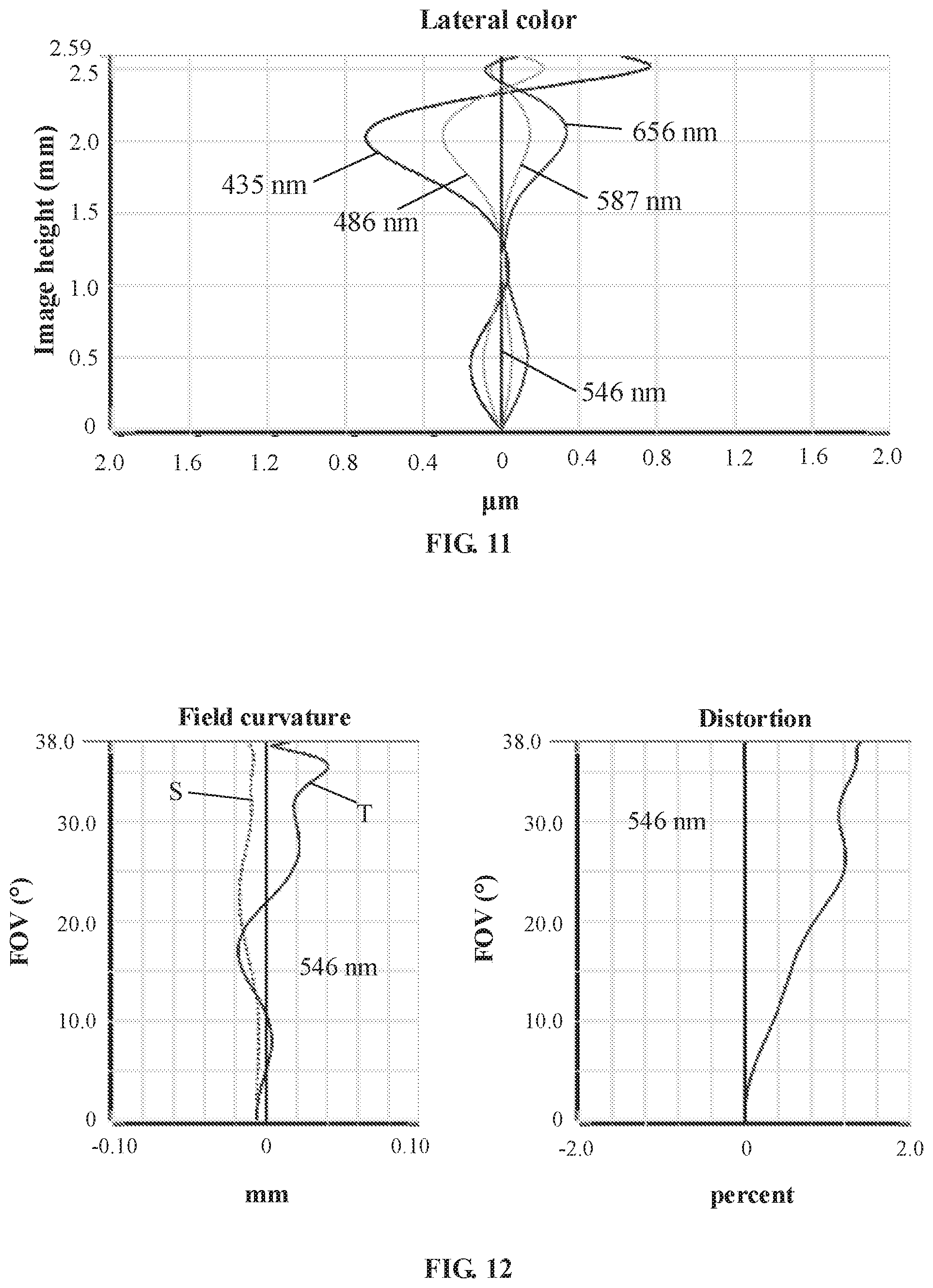
[0037] FIG. 11 is a schematic diagram of a lateral color of the camera optical lens shown in FIG. 9.
[0038] FIG. 12 is a schematic diagram of a field curvature and a distortion of the camera optical lens shown in FIG. 9.
DETAILED DESCRIPTION OF EMBODIMENTS
[0039] The present disclosure will be further illustrated with reference to the accompanying drawings and embodiments.
[0040] To make the objects, technical solutions, and advantages of the present disclosure clearer, embodiments of the present disclosure are described in detail with reference to accompanying drawings in the following. A person of ordinary skill in the art can understand that, in the embodiments of the present disclosure, many technical details are provided to make readers better understand the present disclosure. However, even without these technical details and any changes and modifications based on the following embodiments, technical solutions required to be protected by the present disclosure can be implemented.
Embodiment 1
[0041] Referring to FIGS. 1 to 4 together, the present disclosure provides a camera optical lens 10 of Embodiment 1. In FIG. 1, the left side is an object side and the right side is an image side. The camera optical lens 10 mainly includes five lenses arranged coaxially, which from the object side to the image side are a first lens L1, a second lens L2, a third lens L3, a fourth lens L4 and a fifth lens L5. An aperture S is further provided on an object-side surface of the first lens L1, and a glass plate GF is provided between the fifth lens L5 and an image surface Si. The glass plate GF can be a glass cover plate or an optical filter.
[0042] In an embodiment, the first lens L1 has a positive refractive power; the second lens L2 has a negative refractive power; the third lens L3 has a negative refractive power; the fourth lens L4 has a positive refractive power; and the fifth lens L5 has a negative refractive power.
[0043] Herein, f denotes a focal length of the camera optical lens 10; f1 denotes a focal length of the first lens L1; f2 denotes a focal length of the second lens L2; f4 denotes a focal length of the fourth lens L4; d1 denotes an on-axis thickness of the first lens L1; R3 denotes a curvature radius of an object-side surface of the second lens L2; R9 denotes a curvature radius of an object-side surface of the fifth lens L5; and R10 denotes a curvature radius of an image-side surface of the fifth lens L5. The f, f1, f2, f4, d1, R3, R9, and R10 satisfy following conditions:
-0.35.ltoreq.f1/f2.ltoreq.-0.25 (1)
1.20.ltoreq.(f1+f4)/f.ltoreq.1.30 (2)
0.18.ltoreq.d1/f.ltoreq.0.22 (3)
2.80.ltoreq.R3/f.ltoreq.3.50 (4)
-0.28.ltoreq.(R9+R10)/(R9-R10).ltoreq.-0.24 (5)
[0044] Herein, condition (1) specifies a ratio between the focal length of the first lens L1 to the focal length of the second lens L2, which can effectively balance a spherical aberration and a field curvature amount of the camera optical lens 10 within a range specified by condition (1).
[0045] Condition (2) specifies a ratio between a sum of the focal length of the first lens L1 and the focal length of the fourth lens L4 to the total focal length of the camera optical lens 10, such that within a range specified by condition (2), the camera optical lens 10 can have a better imaging quality and a lower sensitivity through a reasonable distribution of the focal length.
[0046] Condition (3) specifies a ratio between the on-axis thickness of the first lens L1 to the total focal length of the camera optical lens 10, thereby facilitating compressing the total length of the camera optical lens 10 and realizing an ultra-thin effect within a range specified by condition (3).
[0047] Condition (4) specifies a ratio between the curvature radius of the object-side surface of the third lens L3 to the total focal length of the camera optical lens 10, thereby facilitating improving an optical performance of the camera optical lens 10 within a range specified by condition (4).
[0048] Condition (5) specifies a shape of the fifth lens L5, which can alleviate a deflection degree of a light passing through the lens and effectively reduce the aberration within a range specified by condition (5).
[0049] In an embodiment, f5 denotes a focal length of the fifth lens L5. The f5 and f satisfy following condition:
-0.45.ltoreq.f5/f.ltoreq.-0.35 (6)
[0050] Condition (6) specifies a ratio between the focal length of the fifth lens L5 to the total focal length of the camera optical lens 10, such that within a range specified by condition (6), the camera optical lens 10 can have a better imaging quality and a lower sensitivity through a reasonable distribution of the focal length.
[0051] In an embodiment, R1 denotes a curvature radius of the object-side surface of the first lens L1; R2 denotes a curvature radius of an image-side surface of the first lens L; and TTL denotes from the object-side surface of the first lens L1 to the image surface Si of the camera optical lens 10. The f1, f, R1, R2, d1 and TTL satisfy following conditions:
0.36.ltoreq.f1/f.ltoreq.1.12 (7)
-2.89.ltoreq.(R1+R2)/(R1-R2).ltoreq.-0.95 (8)
0.08.ltoreq.d1/TTL.ltoreq.0.27 (9)
[0052] Herein, condition (7) specifies a ratio between the focal length of the first lens L1 to the total focal length of the camera optical lens 10. Within a range specified by condition (7), the first lens L1 has an appropriate positive refractive power, thereby facilitating reducing an aberration of the camera optical lens while facilitating a development towards ultra-thin and wide-angle lenses.
[0053] Condition (8) specifies a shape of the first lens L1 such that within a range specified by condition (8), the first lens L can effectively correct a spherical aberration of the camera optical lens.
[0054] Condition (9) specifies a ratio between a thickness of the first lens L1 to the total track length of the camera optical lens 10, which facilitates achieving the ultra-thin effect within a range specified by condition (9).
[0055] In an embodiment, R4 denotes a curvature radius of an image-side surface of the second lens L2; and d3 denotes an on-axis thickness of the second lens L2. The f2, f, R3, R4, d3, TTL satisfy following conditions:
-5.91.ltoreq.f2/f-1.43 (10)
0.91.ltoreq.(R3+R4)/(R3-R4).ltoreq.3.61 (11)
0.03.ltoreq.d3/TTL.ltoreq.0.09 (12)
[0056] Herein, condition (10) specifies a ratio between the focal length of the second lens L2 to the total focal length of the camera optical lens 10. Within a range specified by condition (10), by controlling a negative refractive power of the second lens L2 within a reasonable range, a correction of the aberration of the camera optical lens is facilitated.
[0057] Condition (11) specifies a shape of the second lens L2. Within a range specified by condition (11), a development towards ultra-thin and wide-angle lenses would facilitate correcting a problem of an on-axis aberration.
[0058] Condition (12) specifies a ratio between a thickness of the second lens L2 to the total track length of the camera optical lens 10, which facilitates achieving the ultra-thin effect within a range specified by condition (12).
[0059] In an embodiment, f3 denotes a focal length of the third lens L3; R5 denotes a curvature radius of an object-side surface of the third lens L3; R6 denotes a curvature radius of an image-side surface of the third lens L3; and d5 denotes an on-axis thickness of the third lens L3. The f3, f, R5, R6, d5 and TTL satisfy following conditions:
-14.56.ltoreq.f3/f.ltoreq.-2.49 (13)
-6.18.ltoreq.(R5+R6)/(R5-R6).ltoreq.-0.96 (14)
0.04.ltoreq.d5/TTL.ltoreq.0.12 (15)
[0060] Herein, condition (13) specifies a ratio between the focal length of the third lens L3 to the total focal length of the camera optical lens 10, such that within a range specified by condition (13), the camera optical lens 10 can have a better imaging quality and a lower sensitivity through a reasonable distribution of a refractive power.
[0061] Condition (14) specifies a shape of the third lens L3, thereby facilitating shaping of the third lens L3 and avoiding bad shaping and generation of stress due to an the overly large surface curvature of the third lens L3 within a range specified by condition (14).
[0062] Condition (15) specifies a ratio between a thickness of the third lens L3 to from the object-side surface of the first lens L1 to the image surface Si of the camera optical lens 10 along an optical axis 10, which facilitates achieving the ultra-thin effect within a range specified by condition (15).
[0063] In an embodiment, R7 denotes a curvature radius of an object-side surface of the fourth lens L4; R8 denotes a curvature radius of an image-side surface of the fourth lens L4; and d7 denotes an on-axis thickness of the fourth lens L4. The f4, f, R7, R8, d7 and TTL satisfy following conditions:
0.23.ltoreq.f4/f.ltoreq.0.83 (16)
0.52.ltoreq.(R7+R8)/(R7-R8).ltoreq.1.86 (17)
0.11.ltoreq.d7/TTL.ltoreq.0.39 (18)
[0064] Herein, condition (16) specifies a ratio between the focal length of the fourth lens L4 to the total focal length of the camera optical lens 10, such that within a range specified by condition (16), the camera optical lens 10 can have a better imaging quality and a lower sensitivity through a reasonable distribution of a refractive power.
[0065] Condition (17) specifies a shape of the fourth lens L4. Within a range specified by condition (17), a development towards ultra-thin and wide-angle lens would facilitate correcting such a problem as an off-axis aberration.
[0066] Condition (18) specifies a ratio between a thickness of the fourth lens L4 to the total track length of the camera optical lens 10, which facilitates achieving the ultra-thin effect within a range specified by condition (18).
[0067] In an embodiment, d9 denotes an on-axis thickness of the fifth lens L5. The d9 and TTL satisfy following condition:
0.03.ltoreq.d9/TTL.ltoreq.0.20 (19)
[0068] Condition (19) specifies a ratio between a thickness of the fifth lens L5 to the total track length of the camera optical lens 10, which facilitates achieving the ultra-thin effect within a range specified by condition (19).
[0069] In addition, in the camera optical lens 10 provided in an embodiment, the surface of each lens can be set as an aspheric surface. The aspheric surface is easily made into a shape other than a spherical surface, and more control variables are obtained to absorb the aberration, thereby decreasing the number of lenses used. Therefore, the total length of the camera optical lens 10 can be effectively reduced. In an embodiment, both the object-side surface and the image-side surface of each lens are aspheric.
[0070] It is worth mentioning that since the first lens L1, the second lens L2, the third lens L3, the fourth lens L4 and the fifth lens L5 have the aforementioned structure and parameter relationship, the camera optical lens 10 can reasonably distribute the refractive power, the interval and the shape of each lens, and thus correct various aberrations.
[0071] In an embodiment, TTL/IH.ltoreq.1.55 and FOV.gtoreq.74.00.degree., where TTL denotes a total optical length from the object-side surface of the first lens L1 to the image surface Si of the camera optical lens 10 along an optical axis; IH denotes an image height of the camera optical lens; and FOV denotes a field of view. In this way, the camera optical lens 10 has the good optical imaging performance while meeting the design requirements of wide-angle and ultra-thinness.
[0072] In the following, examples will be used to describe the camera optical lens 10 of the present disclosure. The symbols recorded in each example will be described as follows. Furthermore, the focal length, on-axis distance, curvature radius, on-axis thickness, total optical length from the object-side surface of the first lens to the image surface of the camera optical lens along the optical axis, inflexion point position, and arrest point position are all in units of mm.
[0073] In addition, inflexion points and/or arrest points can be arranged on the object-side surface and/or the image-side surface of each lens, so as to satisfy the demand for high quality imaging. The description below can be referred for specific implementations.
[0074] The following show the design data of the camera optical lens 10 shown in FIG. 1.
[0075] Table 1 lists the curvature radius R of the object-side surface and the curvature radius R of the image-side surface of the first lens L1 to the fifth lens L5 constituting the camera optical lens 10 in Embodiment 1 of the present disclosure, the on-axis thickness of each lens, the distance d between two adjacent lenses, a refractive index nd and an Abbe number vd.
TABLE-US-00001 TABLE 1 R d nd .nu.d S1 .infin. d0= -0.235 R1 1.121 d1= 0.639 nd1 1.5444 .nu.1 55.82 R2 6.188 d2= 0.041 R3 10.530 d3= 0.234 nd2 1.6700 .nu.2 19.39 R4 3.611 d4= 0.278 R5 -6.272 d5= 0.312 nd3 1.6700 .nu.3 19.39 R6 -12.281 d6= 0.222 R7 -8.385 d7= 0.841 nd4 1.5444 .nu.4 55.82 R8 -0.895 d8= 0.158 R9 -1.205 d9= 0.287 nd5 1.5438 .nu.5 56.03 R10 2.050 d10= 0.257 R11 .infin. d11= 0.210 ndg 1.5168 .nu.g 64.17 R12 .infin. d12= 0.382
[0076] In the above table, meanings of various symbols will be described as follows.
[0077] S1: aperture;
[0078] R: curvature radius of an optical surface, a central curvature radius for a lens;
[0079] R1: curvature radius of the object-side surface of the first lens L1;
[0080] R2: curvature radius of the image-side surface of the first lens L1;
[0081] R3: curvature radius of the object-side surface of the second lens L2;
[0082] R4: curvature radius of the image-side surface of the second lens L2;
[0083] R5: curvature radius of the object-side surface of the third lens L3;
[0084] R6: curvature radius of the image-side surface of the third lens L3;
[0085] R7: curvature radius of the object-side surface of the fourth lens L4;
[0086] R8: curvature radius of the image-side surface of the fourth lens L4;
[0087] R9: curvature radius of the object-side surface of the fifth lens L5;
[0088] R10: curvature radius of the image-side surface of the fifth lens L5;
[0089] R11: curvature radius of the object-side surface of the glass plate GF;
[0090] R12: curvature radius of the image-side surface of the glass plate GF;
[0091] d: on-axis thickness of a lens, an on-axis distance between lens;
[0092] d0: on-axis distance from the aperture Si to the object-side surface of the first lens L1;
[0093] d1: on-axis thickness of the first lens L1;
[0094] d2: on-axis distance from the image-side surface of the first lens L1 to the object-side surface of the second lens L2;
[0095] d3: on-axis thickness of the second lens L2;
[0096] d4: on-axis distance from the image-side surface of the second lens L2 to the object-side surface of the third lens L3;
[0097] d5: on-axis thickness of the third lens L3;
[0098] d6: on-axis distance from the image-side surface of the third lens L3 to the object-side surface of the fourth lens L4;
[0099] d7: on-axis thickness of the fourth lens L4;
[0100] d8: on-axis distance from the image-side surface of the fourth lens L4 to the object-side surface of the fifth lens L5;
[0101] d9: on-axis thickness of the fifth lens L5;
[0102] d10: on-axis distance from the image-side surface of the fifth lens L5 to the object-side surface of the glass plate GF;
[0103] d11: on-axis thickness of the glass plate GF;
[0104] d12: on-axis distance from the image-side surface of the glass plate GF to the image surface Si;
[0105] nd: refractive index of the d line;
[0106] nd1: refractive index of the d line of the first lens L1;
[0107] nd2: refractive index of the d line of the second lens L2;
[0108] nd3: refractive index of the d line of the third lens L3;
[0109] nd4: refractive index of the d line of the fourth lens L4;
[0110] nd5: refractive index of the d line of the fifth lens L5;
[0111] ndg: refractive index of the d line of the glass plate GF;
[0112] vd: abbe number;
[0113] v1: abbe number of the first lens L1;
[0114] v2: abbe number of the second lens L2;
[0115] v3: abbe number of the third lens L3;
[0116] v4: abbe number of the fourth lens L4;
[0117] v5: abbe number of the fifth lens L5;
[0118] vg: abbe number of the glass plate GF.
TABLE-US-00002 TABLE 2 Conic coefficient Aspheric surface coefficients k A4 A6 A8 A10 R1 -5.4895E-02 -2.4131E-02 2.3154E-01 -1.4763E+00 4.5048E+00 R2 -2.2926E+02 -8.1156E-02 -6.8739E-01 4.7997E+00 -1.6172E+01 R3 1.3428E+02 -1.8800E-01 4.2517E-01 2.3312E-01 -3.5965E-01 R4 2.6598E+01 -1.8148E-01 2.5884E+00 -2.0733E+01 1.0985E+02 R5 2.0724E+00 -3.9011E-01 1.2842E+00 -1.1276E+01 5.9154E+01 R6 -3.8790E+02 -2.9301E-01 5.4684E-02 8.8145E-01 -3.7245E+00 R7 -5.8292E-02 -2.1473E-01 1.7700E-01 -4.5188E-01 7.5999E-01 R8 -1.0210E+00 4.2533E-01 -5.8088E-01 6.7327E-01 -4.9221E-01 R9 -5.5559E+00 -7.2325E-02 7.0158E-02 -2.2126E-02 4.0933E-03 R10 -2.3202E+01 -1.0975E-01 8.5442E-02 -5.5110E-02 2.1112E-02 Aspheric surface coefficients A12 A14 A16 A18 A20 R1 -7.7621E+00 7.4107E+00 -6.2199E+00 6.8153E+00 -4.1777E+00 R2 3.2412E+01 -3.8834E+01 2.4464E+01 -1.5034E+01 1.5209E+01 R3 1.1613E-01 -5.0213E+00 8.9422E+00 -3.0259E+00 7.7097E-01 R4 -3.4558E+02 5.8917E+02 -3.8291E+02 -1.9761E+02 2.3769E+02 R5 -1.8351E+02 3.1061E+02 -2.2371E+02 3.4636E+00 -2.3343E+01 R6 8.8142E+00 -9.6125E+00 3.6831E+00 2.7782E-01 -1.8740E-01 R7 -4.8626E-01 1.3273E-01 -3.1347E-02 -2.7392E-03 7.3510E-03 R8 2.0885E-01 -4.7193E-02 4.6570E-03 -1.5429E-04 2.0386E-05 R9 -9.8266E-04 2.6798E-04 -3.1748E-05 -8.0294E-07 3.0260E-07 R10 -4.7886E-03 6.3973E-04 -4.4784E-05 4.2975E-07 1.3172E-07
[0119] In table 2, K is a conic coefficient, and A4, A6, A8, A10, A12, A14, A16, A18 and A20 are aspheric surface coefficients.
y=(x.sup.2/R)/[1+{1-(k+1)(x.sup.2/R.sup.2)}.sup.1/2]+A4x.sup.4+A6x.sup.6- +A8x.sup.8+A10x.sup.10+A12x.sup.12+A14x.sup.14+A16x.sup.16+A18x.sup.18+A20- x.sup.20
[0120] For convenience, an aspheric surface of each lens surface uses the aspheric surfaces shown in the above formula. However, the present disclosure is not limited to the aspherical polynomials form shown in the formula.
TABLE-US-00003 TABLE 3 Number(s) of Inflexion point Inflexion point inflexion points position 1 position 2 P1R1 P1R2 1 0.265 P2R1 P2R2 P3R1 P3R2 2 0.725 0.775 P4R1 2 0.855 1.015 P4R2 2 0.885 1.375 P5R1 1 0.895 P5R2 2 0.435 2.015
TABLE-US-00004 TABLE 4 Number(s) of Arrest point arrest points position 1 P1R1 P1R2 1 0.495 P2R1 P2R2 P3R1 P3R2 P4R1 P4R2 P5R1 1 1.775 P5R2 1 0.975
[0121] Table 3 and Table 4 show design data of inflexion points and arrest points of the camera optical lens 10 according to an embodiment of the present disclosure. P1R1 and P1R2 represent the object-side surface and the image-side surface of the first lens L1, P2R1 and P2R2 represent the object-side surface and the image-side surface of the second lens L2, P3R1 and P3R2 represent the object-side surface and the image-side surface of the third lens L3, P4R1 and P4R2 represent the object-side surface and the image-side surface of the fourth lens L4, P5R1 and P5R2 represent the object-side surface and the image-side surface of the fifth lens L5. The data in the column named "inflexion point position" refer to vertical distances from inflexion points arranged on each lens surface to the optic axis of the camera optical lens 10. The data in the column named "arrest point position" refer to vertical distances from arrest points arranged on each lens surface to the optical axis of the camera optical lens 10.
[0122] In addition, the following Table 13 further lists the values corresponding to various parameters and conditions in Embodiment 1.
[0123] FIG. 2 and FIG. 3 illustrate a longitudinal aberration and a lateral color with wavelengths of 435 nm, 486 nm, 546 nm, 587 nm and 656 nm after passing the camera optical lens 10, respectively. FIG. 4 illustrates a field curvature and a distortion with a wavelength of 546 nm after passing the camera optical lens 10. Afield curvature S in FIG. 4 is a field curvature in a sagittal direction, and T is a field curvature in a tangential direction.
[0124] In an embodiment, an image height of the camera optical lens 10 is IH, a field of view is FOV, and an entrance pupil diameter is ENPD, where IH=2.59 mm, the FOV=74.20.degree. in a diagonal direction, and ENPD=1.528. Thus, the camera optical lens 10 has a large aperture, ultra-thinness and wide angle, thereby achieving an excellent imaging performance.
Embodiment 2
[0125] FIG. 5 is a schematic structural diagram of a camera optical lens 20 in Embodiment 2. Embodiment 2 is basically the same as Embodiment 1 and involves symbols in the following tables having the same meanings as Embodiment 1, so the same parts are not repeated here, and only the differences therebetween will be described in the following.
[0126] Table 5 and Table 6 show design data of a camera optical lens 20 in Embodiment 2 of the present disclosure.
TABLE-US-00005 TABLE 5 R d nd .nu.d S1 .infin. d0= -0.205 R1 1.150 d1= 0.601 nd1 1.5444 .nu.1 55.82 R2 6.524 d2= 0.019 R3 9.272 d3= 0.200 nd2 1.6700 .nu.2 19.39 R4 3.826 d4= 0.315 R5 -6.812 d5= 0.282 nd3 1.6700 .nu.3 19.39 R6 -37.623 d6= 0.203 R7 -43.193 d7= 1.037 nd4 1.5444 .nu.4 55.82 R8 -0.828 d8= 0.120 R9 -1.055 d9= 0.522 nd5 1.5438 .nu.5 56.03 R10 1.868 d10= 0.257 R11 .infin. d11= 0.210 ndg 1.5168 .nu.g 64.17 R12 .infin. d12= 0.234
TABLE-US-00006 TABLE 6 Conic coefficient Aspheric surface coefficients k A4 A6 A8 A10 R1 3.2462E-03 -1.6201E-02 1.9838E-01 -1.4433E+00 4.5362E+00 R2 -4.8538E+02 -3.5317E-02 -5.9054E-01 4.8359E+00 -1.6459E+01 R3 1.6725E+02 -1.7167E-01 6.4925E-01 -8.1170E-02 -7.5649E-01 R4 2.8088E+01 -1.1159E-01 2.5494E+00 -2.4372E+01 1.4218E+02 R5 4.0890E+00 -4.3380E-01 1.4247E+00 -1.2444E+01 6.2973E+01 R6 8.9012E+02 -3.0498E-01 8.3943E-02 8.8178E-01 -3.3956E+00 R7 6.2598E+02 -2.0785E-01 2.8283E-01 -5.2750E-01 7.2604E-01 R8 -1.1641E+00 4.2531E-01 -6.0517E-01 6.8823E-01 -4.9485E-01 R9 -5.0116E+00 -7.8458E-02 7.1929E-02 -2.3394E-02 4.0626E-03 R10 -1.2822E+01 -9.3494E-02 7.9356E-02 -4.9408E-02 1.9364E-02 Aspheric surface coefficients A12 A14 A16 A18 A20 R1 -7.9306E+00 7.4694E+00 -5.8272E+00 6.2167E+00 -4.0888E+00 R2 3.1814E+01 -3.9046E+01 2.6128E+01 -1.1898E+01 9.6219E+00 R3 -2.6851E-01 -1.7377E+00 1.3530E+01 -2.6903E+01 1.3821E+01 R4 -4.6343E+02 6.9560E+02 1.4032E+02 -1.7903E+03 1.5896E+03 R5 -1.8834E+02 3.0139E+02 -2.1442E+02 7.1485E+01 -1.1723E+02 R6 6.0483E+00 -3.8872E+00 -6.0750E-01 6.3128E-01 4.6839E-01 R7 -4.8481E-01 1.5295E-01 -1.9386E-02 -9.7240E-03 5.9736E-03 R8 2.1102E-01 -4.8638E-02 4.7141E-03 7.1310E-06 -1.0266E-05 R9 -9.1002E-04 2.8948E-04 -2.9288E-05 -1.7472E-06 -1.2799E-07 R10 -4.7907E-03 6.9290E-04 -4.4723E-05 -8.2050E-07 1.9166E-07
[0127] In table 6, K is a conic coefficient, and A4, A6, A8, A10, A12, A14, A16, A18 and A20 are aspheric surface coefficients.
y=(x.sup.2/R)/[1+{1-(k+1)(x.sup.2/R.sup.2)}.sup.1/2]+A4x.sup.4+A6x.sup.6- +A8x.sup.8+A10x.sup.10+A12x.sup.12+A14x.sup.14+A16x.sup.16+A18x.sup.18+A20- x.sup.20
[0128] For convenience, an aspheric surface of each lens surface uses the aspheric surfaces shown in the above formula. However, the present disclosure is not limited to the aspherical polynomials form shown in the formula.
[0129] Table 7 and table 8 show design data of inflexion points and arrest points of each lens of the camera optical lens 20 lens.
TABLE-US-00007 TABLE 7 Number(s) of Inflexion point Inflexion point Inflexion point inflexion points position 1 position 2 position 3 P1R1 1 0.745 P1R2 1 0.285 P2R1 P2R2 P3R1 P3R2 P4R1 3 0.845 1.055 1.135 P4R2 2 0.855 1.515 P5R1 2 0.935 1.755 P5R2 1 0.555
TABLE-US-00008 TABLE 8 Number of Arrest point arrest points position 1 P1R1 P1R2 1 0.605 P2R1 P2R2 P3R1 P3R2 P4R1 P4R2 P5R1 P5R2 1 1.335
[0130] In addition, the following Table 13 further lists the values corresponding to various parameters and conditions in Embodiment 2.
[0131] FIG. 6 and FIG. 7 illustrate a longitudinal aberration and a lateral color with wavelengths of 435 nm, 486 nm, 546 nm, 587 nm and 656 nm after passing the camera optical lens 20, respectively. FIG. 8 illustrates a field curvature and a distortion with a wavelength of 546 nm after passing the camera optical lens 20. A field curvature S in FIG. 8 is a field curvature in a sagittal direction, and T is a field curvature in a tangential direction.
[0132] In an embodiment, an image height of the camera optical lens 20 is IH, a field of view is FOV, and an entrance pupil diameter is ENPD, where IH=2.59 mm, the FOV=75.00.degree. in a diagonal direction, and ENPD=1.500. Thus, the camera optical lens 20 has a large aperture and is ultra-thin and wide-angled, thereby achieving an excellent imaging performance.
Embodiment 3
[0133] FIG. 9 is a schematic structural diagram of a camera optical lens 30 in Embodiment 3. Embodiment 3 is basically the same as Embodiment 1 and involves symbols in the following tables having the same meanings as Embodiment 1, so the same parts are not repeated here, and only the differences therebetween will be described in the following.
[0134] Table 9 and Table 10 show design data of a camera optical lens 30 in Embodiment 3 of the present disclosure.
TABLE-US-00009 TABLE 9 R d nd .nu.d S1 .infin. d0= -0.235 R1 1.125 d1= 0.685 nd1 1.5444 .nu.1 55.82 R2 6.178 d2= 0.044 R3 11.228 d3= 0.219 nd2 1.6700 .nu.2 19.39 R4 3.270 d4= 0.244 R5 -10.007 d5= 0.282 nd3 1.6700 .nu.3 19.39 R6 -27.353 d6= 0.212 R7 -11.494 d7= 0.816 nd4 1.5444 .nu.4 55.82 R8 -0.917 d8= 0.193 R9 -1.290 d9= 0.251 nd5 1.5438 .nu.5 56.03 R10 2.109 d10= 0.256 R11 .infin. d11= 0.210 ndg 1.5168 .nu.g 64.17 R12 .infin. d12= 0.374
TABLE-US-00010 TABLE 10 Conic coefficient Aspherical surface coefficients k A4 A6 A8 A10 R1 -1.3851E-02 -2.6540E-02 2.3007E-01 -1.4536E+00 4.5378E+00 R2 -1.4464E+02 -3.3608E-02 -6.5822E-01 4.5408E+00 -1.6844E+01 R3 1.8164E+02 -9.4020E-02 3.1390E-01 -1.7587E-01 -7.8857E-01 R4 2.1498E+01 -1.1077E-01 2.2925E+00 -2.0349E+01 1.1035E+02 R5 -2.6847E+02 -4.2224E-01 1.2383E+00 -1.1035E+01 5.9514E+01 R6 7.5585E+02 -3.2132E-01 1.2726E-01 8.1662E-01 -3.8220E+00 R7 7.5215E+01 -2.4072E-01 2.1134E-01 -4.4064E-01 7.5947E-01 R8 -9.2555E-01 4.1135E-01 -5.6546E-01 6.7238E-01 -4.9264E-01 R9 -7.6159E+00 -7.0837E-02 7.0682E-02 -2.2114E-02 4.0913E-03 R10 -1.7050E+01 -1.0990E-01 8.7580E-02 -5.5131E-02 2.1090E-02 Aspherical surface coefficients A12 A14 A16 A18 A20 R1 -7.6931E+00 7.3015E+00 -6.5318E+00 6.3885E+00 -2.6154E+00 R2 3.2147E+01 -3.6411E+01 3.1362E+01 -1.0452E+01 -5.8946E+00 R3 8.3379E-01 -2.8721E+00 1.3254E+01 2.9811E+00 -1.8504E+01 R4 -3.4682E+02 5.8501E+02 -3.8660E+02 -1.7936E+02 2.9316E+02 R5 -1.8480E+02 3.0588E+02 -2.2181E+02 2.0045E+01 -2.0192E+01 R6 8.8500E+00 -9.5421E+00 3.7355E+00 1.9465E-01 -1.7165E-01 R7 -4.9083E-01 1.2760E-01 -3.5268E-02 -3.3599E-03 1.0338E-02 R8 2.0889E-01 -4.7130E-02 4.6812E-03 -1.5104E-04 -1.0880E-05 R9 -9.8177E-04 2.6888E-04 -3.1524E-05 -7.9634E-07 2.7597E-07 R10 -4.7891E-03 6.4066E-04 -4.4545E-05 4.8183E-07 1.2736E-07
[0135] In table 10, K is a conic coefficient, and A4, A6, A8, A10, A12, A14, A16, A18 and A20 are aspheric surface coefficients.
y=(x.sup.2/R)/[1+{1-(k+1)(x.sup.2/R.sup.2)}.sup.1/2]+A4x.sup.4+A6x.sup.6- +A8x.sup.8+A10x.sup.10+A12x.sup.12+A14x.sup.14+A16x.sup.16+A18x.sup.18+A20- x.sup.20
[0136] For convenience, an aspheric surface of each lens surface uses the aspheric surfaces shown in the above formula. However, the present disclosure is not limited to the aspherical polynomials form shown in the formula.
[0137] Table 11 and Table 12 show design data inflexion points and arrest points of the respective lenses in the camera optical lens 30.
TABLE-US-00011 TABLE 11 Number(s) of Inflexion point Inflexion point inflexion points position 1 position 2 P1R1 P1R2 2 0.325 0.625 P2R1 P2R2 P3R1 P3R2 P4R1 2 0.825 0.985 P4R2 2 0.895 1.245 P5R1 1 0.855 P5R2 2 0.475 1.735
TABLE-US-00012 TABLE 12 Number of Arrest point Arrest point arrest points position 1 position 2 P1R1 P1R2 1 0.535 P2R1 P2R2 P3R1 P3R2 P4R1 P4R2 P5R1 1 1.575 P5R2 2 1.075 2.015
[0138] In addition, the following Table 13 further lists the values corresponding to various parameters and conditions in Embodiment 3.
[0139] FIG. 10 and FIG. 11 illustrate a longitudinal aberration and a lateral color with wavelengths of 435 nm, 486 nm, 546 nm, 587 nm and 656 nm after passing the camera optical lens 30, respectively. FIG. 12 illustrates a field curvature and a distortion with a wavelength of 546 nm after passing the camera optical lens 30. Afield curvature S in FIG. 12 is a field curvature in a sagittal direction, and T is a field curvature in a tangential direction.
[0140] In an embodiment, an image height of the camera optical lens 30 is IH, a field of view is FOV, and an entrance pupil diameter is ENPD, where IH=2.59 mm, the FOV=76.00.degree. in a diagonal direction, and ENPD=1.462. Thus, the camera optical lens 30 has a large aperture, ultra-thinness and wide angle, thereby achieving an excellent imaging performance.
[0141] The following table 13 lists the values of the corresponding parameters in Embodiment 1, Embodiment 2, and Embodiment 3 and conditions (1), (2), (3), (4) and (5) according to the above conditions.
TABLE-US-00013 TABLE 13 Parameters and Embodi- Embodi- Embodi- conditions ment 1 ment 2 ment 3 Remarks f1/f2 -0.29 -0.25 -0.35 Condition (1) (f1 + f4)/f 1.24 1.21 1.30 Condition (2) d1/f 0.19 0.18 0.21 Condition (3) R3/f 3.13 2.81 3.49 Condition (4) (R9 + R10)/ -0.26 -0.28 -0.24 Condition (5) (R9 - R10) f 3.361 3.300 3.217 f1 2.397 2.457 2.400 f2 -8.216 -9.749 -6.881 f3 -19.309 -12.311 -23.423 f4 1.762 1.531 1.774 f5 -1.348 -1.161 -.428 f12 3.003 3.005 3.159 FNO 2.20 2.20 2.20
[0142] F12 is a combined focal length of the first lens L1 and second lens L2.
[0143] It can be appreciated by one having ordinary skill in the art that the description above is only embodiments of the present disclosure. In practice, one having ordinary skill in the art can make various modifications to these embodiments in forms and details without departing from the scope of the present disclosure.
* * * * *
D00000
D00001
D00002
D00003
D00004
D00005
D00006
XML
uspto.report is an independent third-party trademark research tool that is not affiliated, endorsed, or sponsored by the United States Patent and Trademark Office (USPTO) or any other governmental organization. The information provided by uspto.report is based on publicly available data at the time of writing and is intended for informational purposes only.
While we strive to provide accurate and up-to-date information, we do not guarantee the accuracy, completeness, reliability, or suitability of the information displayed on this site. The use of this site is at your own risk. Any reliance you place on such information is therefore strictly at your own risk.
All official trademark data, including owner information, should be verified by visiting the official USPTO website at www.uspto.gov. This site is not intended to replace professional legal advice and should not be used as a substitute for consulting with a legal professional who is knowledgeable about trademark law.