Pre-cooling Device Dehumidifier
Zhou; Rui
U.S. patent application number 16/910452 was filed with the patent office on 2021-02-25 for pre-cooling device dehumidifier. The applicant listed for this patent is NINGBO REFINE MOULD TECHNOLOGY CO., LTD. Invention is credited to Rui Zhou.
| Application Number | 20210055009 16/910452 |
| Document ID | / |
| Family ID | 1000004955453 |
| Filed Date | 2021-02-25 |


| United States Patent Application | 20210055009 |
| Kind Code | A1 |
| Zhou; Rui | February 25, 2021 |
PRE-COOLING DEVICE DEHUMIDIFIER
Abstract
A pre-cooling device dehumidifier includes a compressor, a condenser, an expansion mechanism, a microchannel pre-cooler and an evaporator assembly. During operation, moist air enters from an air inlet of the dehumidifier, and passes through the microchannel pre-cooler to make the moist air to reach a saturated steam state and passes through the evaporator assembly for heat exchange to condense and dehumidify the moist air, and the dehumidified air passes through the condenser for heating and finally discharged from the air outlet, so that the water vapor in the moist air can be condensed into a liquid better to improve the condensation and dehumidification effects of the evaporator and reduce the air humidity effectively, so as to improve the dehumidification effect of the equipment.
| Inventors: | Zhou; Rui; (Zhejiang, CN) | ||||||||||
| Applicant: |
|
||||||||||
|---|---|---|---|---|---|---|---|---|---|---|---|
| Family ID: | 1000004955453 | ||||||||||
| Appl. No.: | 16/910452 | ||||||||||
| Filed: | June 24, 2020 |
| Current U.S. Class: | 1/1 |
| Current CPC Class: | F24F 2003/1446 20130101; F24F 3/153 20130101; F24F 3/1405 20130101; F25B 40/02 20130101 |
| International Class: | F24F 3/14 20060101 F24F003/14; F25B 40/02 20060101 F25B040/02; F24F 3/153 20060101 F24F003/153 |
Foreign Application Data
| Date | Code | Application Number |
|---|---|---|
| Aug 20, 2019 | CN | 201910769197.8 |
Claims
1. A pre-cooling device dehumidifier comprising: a compressor, a condenser, an expansion mechanism, a microchannel pre-cooler and an evaporator assembly, characterized in that moist air enters from an air inlet formed on a casing of the dehumidifier, and passes through the microchannel pre-cooler to make moist air to reach a saturated steam state, and further passes through the evaporator assembly to perform heat exchange in order to condense and dehumidify the moist air, and the dehumidified air passes through the condenser for heating, and finally discharged from the air outlet, wherein a refrigerant used in the condenser, the expansion mechanism, the microchannel pre-cooler, and the evaporator assembly is delivered by a pipeline, and a refrigeration cycle is completed by the compressor.
2. The pre-cooling device dehumidifier as claimed in claim 1, further comprising a throttling capillary installed between the microchannel pre-cooler and the evaporation mechanism for changing a cold fluid refrigerant into a cold liquid refrigerant.
3. The pre-cooling device dehumidifier as claimed in claim 1, wherein the expansion mechanism comprises an expansion device and an auxiliary expansion device, and a hot liquid refrigerant passing through the condenser flows into the expansion device and the auxiliary expansion device separately. Page 4
4. The pre-cooling device dehumidifier as claimed in claim 1, wherein the hot liquid refrigerant flowing out from the condenser passes through the expansion device to expand the volume and reduce the temperature and pressure of the refrigerant before entering into the microchannel pre-cooler.
5. The pre-cooling device dehumidifier as claimed in claim 1, wherein the hot liquid refrigerant flowing out from the condenser passes through the auxiliary expansion device to expand the volume and reduce temperature and pressure of the refrigerant before entering into the subcooler.
6. The pre-cooling device dehumidifier as claimed in claim 5, wherein the subcooler receives a cold liquid refrigerant from the auxiliary expansion device and evaporates the cold liquid refrigerant to form a cold gas refrigerant.
7. The pre-cooling device dehumidifier as claimed in claim 1, wherein the cold gas refrigerant produced by the evaporator assembly and the subcooler reaching a confluence and passing through the compressor becomes a hot gas refrigerant, and then the compressor delivers the hot gas refrigerant to the condenser to complete a refrigeration cycle.
8. The pre-cooling device dehumidifier as claimed in claim 1, wherein the evaporator assembly has one or two evaporators.
Description
FIELD OF THE INVENTION
[0001] The present invention relates to the field of dehumidifiers, and more particularly to a pre-cooling device dehumidifier.
BACKGROUND OF THE INVENTION
[0002] Dehumidifier (also known as humidity extractor, dryer, and moisture remover) is mainly divided into two types: household dehumidifier and industrial dehumidifier, and the dehumidifier is a member of the air-conditioning family. The operating principle of the dehumidifier is to draw moist air into the machine and pass the air through a heat exchanger. Now, the water vapor in the air is condensed into waterdrops, and the processed dry air is discharged from the machine to the outside, and this cycle keeps the indoor humidity at an appropriate relative humidity.
[0003] In reality, the moist air reaching a saturated steam state and passing through an evaporator has the best condensation and dehumidification effects. However, the conventional dehumidifiers generally fail to make the moist air to reach the saturated steam state before entering into the evaporator for heat exchange, and the water vapor passing through the evaporator cannot be condensed into liquid very well, so that the condensation and dehumidification effects of the evaporator is reduced, and the dehumidification effect of the dehumidifier is poor. The present invention discloses a pre-cooling device dehumidifier with a microchannel pre-cooler to overcome the aforementioned drawback of the conventional dehumidifier, and the microchannel pre-cooler can make the moist air to reach the saturated steam state before entering into the evaporator, so that the water vapor in the moist air reaching the saturated steam state during the heat exchange process can be condensed into liquid very well to improve the condensation and dehumidification effects of the evaporator and reduce the air humidity effectively, so as to improve the dehumidification effect of the equipment.
SUMMARY OF THE INVENTION
[0004] In view of the aforementioned drawbacks and the poor dehumidification effect of the conventional dehumidifier, it is a primary objective of the present invention to provide a pre-cooling device dehumidifier to overcome the drawbacks of the prior art that the moist air cannot reach the saturated steam state before entering into the heat exchange process of the evaporator, and the present invention has a microchannel pre-cooler provided for the moist air to enter into the saturated steam state before entering into the evaporator, and the moist air is cooled to reach the saturated steam state during the heat exchange process, so that the water vapor in the moist air can be condensed into liquid very well to improve the condensation and dehumidification effects of the evaporator and reduce the air humidity effectively, so as to improve the dehumidification effect of the equipment.
[0005] To achieve the aforementioned and other objectives, the present invention discloses a pre-cooling device dehumidifier comprising: a compressor, a condenser, an expansion mechanism, a microchannel pre-cooler and an evaporator assembly, characterized in that moist air enters from an air inlet formed on a casing of the dehumidifier, and passes through the microchannel pre-cooler to make moist air to reach a saturated steam state, and further passes through the evaporator assembly to perform heat exchange in order to condense and dehumidify the moist air, and the dehumidified air passes through the condenser for heating, and finally discharged from the air outlet, wherein a refrigerant used in the condenser, the expansion mechanism, the microchannel pre-cooler, and the evaporator assembly is delivered by a pipeline, and a refrigeration cycle is completed by the compressor.
[0006] Further, a throttling capillary is installed between the microchannel pre-cooler and the evaporation mechanism for changing a cold fluid refrigerant into a cold liquid refrigerant.
[0007] Further, the pre-cooling device dehumidifier comprises an expansion device and an auxiliary expansion device, and a hot liquid refrigerant passing through the condenser flows into the expansion device and the auxiliary expansion device separately.
[0008] Further, the hot liquid refrigerant flowing out from the condenser passes through the expansion device to expand the volume and reduce the temperature and pressure of the refrigerant before entering into the microchannel pre-cooler.
[0009] Further, the hot liquid refrigerant flowing out from the condenser passes through the auxiliary expansion device to expand the volume and reduce temperature and pressure of the refrigerant before entering into the subcooler.
[0010] Further, the subcooler receives a cold liquid refrigerant from the auxiliary expansion device and evaporates the cold liquid refrigerant to form a cold gas refrigerant.
[0011] Further, the cold gas refrigerant produced by the evaporator assembly and the subcooler reaching a confluence and passing through the compressor becomes a hot gas refrigerant, and then the compressor delivers the hot gas refrigerant to the condenser to complete a refrigeration cycle.
[0012] Further, the evaporator assembly has one or two evaporators.
[0013] Compared with the prior art, this invention has the following advantages and effects: This invention has a microchannel pre-cooler, so that the moist air can reach the saturated steam state before entering into the evaporator, and the water vapor in the moist air reaching the saturated steam state before entering into the heat exchange can be condensed into liquid very well to improve the condensation and dehumidification of the evaporator and reduce the air humidity, so as to improve the dehumidification effect of the equipment.
[0014] The technical characteristics of the present invention will become apparent with the detailed description of preferred embodiments accompanied with the illustration of related drawings as follows.
BRIEF DESCRIPTION OF THE DRAWINGS
[0015] FIG. 1 is a schematic view of a first embodiment of the present invention;
[0016] FIG. 2 is a schematic view of a second embodiment of the present invention;
[0017] FIG. 3 is a schematic view of a third embodiment of the present invention;
[0018] FIG. 4 is a schematic view showing the status of airflow during the operation of the present invention;
[0019] FIG. 5 is a perspective view of the present invention.
[0020] Brief Description of Numerals Used in the Drawings: 1: Casing; 2: Microchannel pre-cooler; 3: Evaporator assembly; 31: First evaporator; 32: Second evaporator; 4: Condenser; 5: Compressor; 6: Auxiliary expansion device; 7: Throttling capillary; 8: Expansion device; 9: Subcooler.
DESCRIPTION OF THE PREFERRED EMBODIMENTS
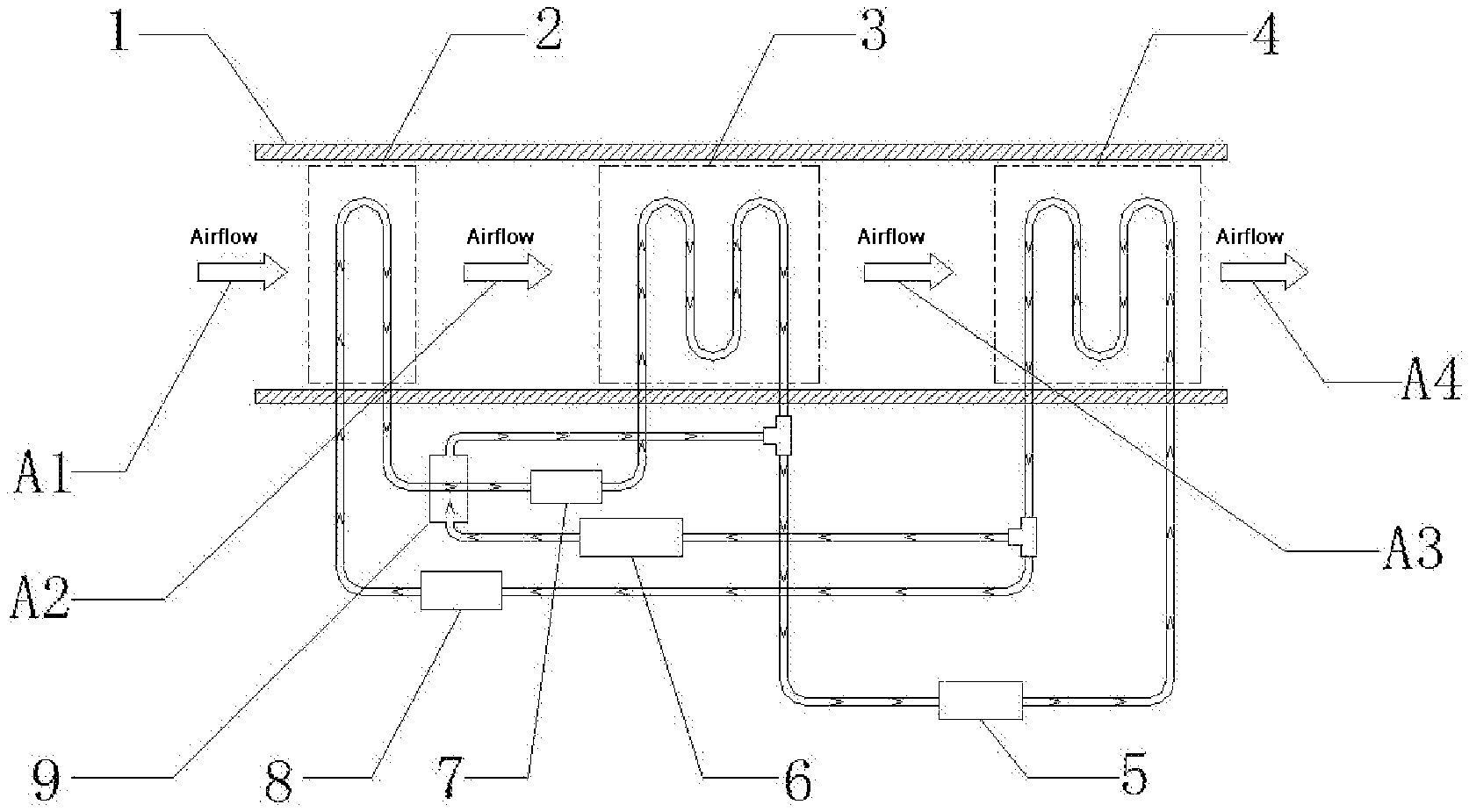
[0021] With reference to FIG. 1 for a pre-cooling device dehumidifier in accordance with the first embodiment of the present invention, the pre-cooling device dehumidifier comprises a casing 1, a microchannel pre-cooling device 2, an evaporator assembly 3, a condenser 4, and an expansion mechanism, wherein the refrigerant used in the microchannel pre-cooling device 2, evaporator assembly 3, condenser 4, and expansion mechanism are delivered by a pipeline, and the compressor 5 is provided for completing a refrigeration cycle.
[0022] During the cycle, the compressor 5 sends a hot gas refrigerant to the condenser 4 to be processed by a heat exchange of the condenser 4 and then the hot liquid refrigerant flows out from the condenser 4 and into the expansion mechanism, wherein the expansion mechanism comprises an expansion device 8 and an auxiliary expansion device 6. After the flow the hot gas refrigerant is divided, a part of the hot liquid refrigerant passing through the expansion device 8 is expanded to reduce the temperature and pressure of the refrigerant and entered into the microchannel pre-cooler 2, and the other part of the hot liquid refrigerant is passed through the auxiliary expansion device 6 and expanded to reduce the temperature and pressure of the refrigerant and entered into the subcooler 9.
[0023] Further, a throttling capillary 7 is installed between the microchannel pre-cooler 2 and the evaporation mechanism 3 and provided for changing a cold fluid refrigerant flowing out from the microchannel pre-cooler 2 into a cold liquid refrigerant, and the cold liquid refrigerant is passed into the evaporation mechanism 3 for a heat exchange. After the heat exchange is completed, the cold liquid refrigerant is changed into cold air refrigerant which flows out from the evaporation mechanism 3.
[0024] Further, the subcooler 9 receives a cold liquid refrigerant the from the auxiliary expansion device 6, and evaporate the cold liquid refrigerant to form a cold gas refrigerant, and the cold gas refrigerant flowing out from the evaporation mechanism 3 and the cold gas refrigerant flowing out from the subcooler 9 are combined and the combined cold gas refrigerant flows towards the compressor 5.
[0025] Further, the cold gas refrigerant produced by the evaporation mechanism 3 and the subcooler 9 is passed through the compressor 5 and changed into a hot gas refrigerant, and then the compressor 5 delivers the hot gas refrigerant into the condenser 4 to complete a refrigeration cycle.
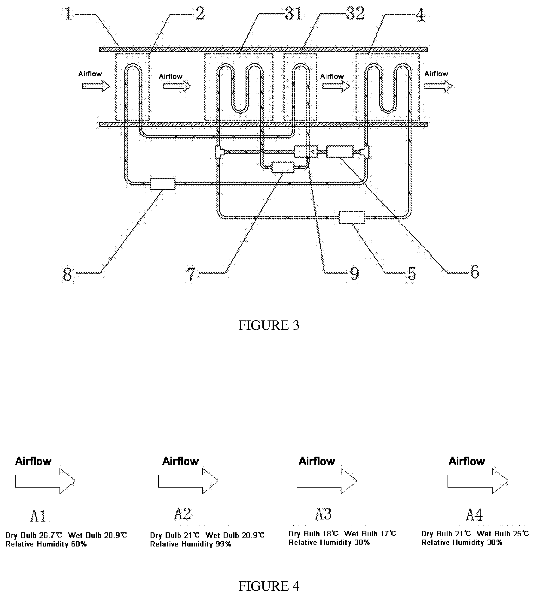
[0026] During the operation of the pre-cooling device dehumidifier, an airflow A1 entering from an air inlet formed on the casing 1 passes through the microchannel pre-cooler 2 to make the moist air to reach a saturated steam state, and the water vapor of the airflow A2 reaching the saturated steam state in the heat exchange process of the evaporation mechanism 3 can be condensed into liquid very well to improve the condensation and dehumidification of the evaporator effectively, and the dehumidified airflow A3 is heated by the condenser 4 and finally the airflow A4 is discharged from the air outlet.
[0027] With reference to FIG. 2 for a pre-cooling device dehumidifier in accordance with the second embodiment of the present invention, the pre-cooling device dehumidifier is based on the first embodiment, and the evaporation mechanism 3 of the second embodiment has two evaporators: a first evaporator 31 and a second evaporator 32 respectively, wherein the cold gas refrigerant flowing out from the subcooler 9 enters into the second evaporator 32 for a heat exchange, and the cold gas refrigerants flowing out from the first evaporator 31 and the second evaporator 32 are combined and entered into the compressor 5 to complete a refrigeration cycle. In the second embodiment 2, the evaporation mechanism 3 has two evaporators, so that when the airflow A2 passes through the evaporation mechanism 3, the condensation and dehumidification can be carried out sufficiently to obtain an airflow A4 having a lower relative humidity to improve the dehumidification effect of the equipment.
[0028] With reference to FIG. 3 for a pre-cooling device dehumidifier in accordance with the second embodiment of the present invention, the pre-cooling device dehumidifier is based on the second embodiment, and the evaporation mechanism 3 also has two evaporators: a first evaporator 31 and a second evaporator 32 respectively, and a throttling capillary 7 is installed between the first evaporator 31 and the second evaporator 32, and a cold fluid refrigerant flowing out from the microchannel pre-cooler flows into the second evaporator 32 for a heat exchange, and the refrigerant flowing out from the throttling capillary 7 after the heat exchange process enters into the first evaporator 31, wherein the cold gas refrigerant flowing out from the subcooler 9 and the cold gas refrigerant flowing out from the first evaporator 31 are combined and entered into the compressor 5 to complete a refrigeration cycle.
[0029] This invention has a microchannel pre-cooler to make the moist air to reach the saturated steam state before entering into the evaporator, and the water vapor in the moist air reaching the saturated steam state in the heat exchange process conducted by the evaporator can be condensed into liquid very well to improve the condensation and dehumidification effects of the evaporator and reduce the air humidity effectively, so as to improve the dehumidification effect of the equipment. Since there are two evaporators of the evaporation mechanism in the second embodiment, therefore the moist air can be condensed and dehumidified very well to obtain air with a low relative humidity and improve the dehumidification effect of the equipment.
[0030] While the invention has been described by means of specific embodiments, numerous modifications and variations could be made thereto by those skilled in the art without departing from the scope and spirit of the invention as set forth in the claims.
* * * * *
D00000
D00001
D00002
D00003
XML
uspto.report is an independent third-party trademark research tool that is not affiliated, endorsed, or sponsored by the United States Patent and Trademark Office (USPTO) or any other governmental organization. The information provided by uspto.report is based on publicly available data at the time of writing and is intended for informational purposes only.
While we strive to provide accurate and up-to-date information, we do not guarantee the accuracy, completeness, reliability, or suitability of the information displayed on this site. The use of this site is at your own risk. Any reliance you place on such information is therefore strictly at your own risk.
All official trademark data, including owner information, should be verified by visiting the official USPTO website at www.uspto.gov. This site is not intended to replace professional legal advice and should not be used as a substitute for consulting with a legal professional who is knowledgeable about trademark law.