Carbon Nanosheet And Manufacturing Method Therefor
HORI; Masaru ; et al.
U.S. patent application number 16/957890 was filed with the patent office on 2021-02-25 for carbon nanosheet and manufacturing method therefor. This patent application is currently assigned to NATIONAL UNIVERSITY CORPORATION TOKAI NATIONAL HIGHER EDUCATION AND RESEARCH SYSTEM. The applicant listed for this patent is NATIONAL UNIVERSITY CORPORATION TOKAI NATIONAL HIGHER EDUCATION AND RESEARCH SYSTEM. Invention is credited to Masaru HORI, Kenji ISHIKAWA, Hiroki KONDO.
| Application Number | 20210053830 16/957890 |
| Document ID | / |
| Family ID | 1000005252627 |
| Filed Date | 2021-02-25 |


View All Diagrams
| United States Patent Application | 20210053830 |
| Kind Code | A1 |
| HORI; Masaru ; et al. | February 25, 2021 |
CARBON NANOSHEET AND MANUFACTURING METHOD THEREFOR
Abstract
A carbon nanosheet, which is a sheet-form carbon nanomaterial having a larger area as compared with that of a similar conventional product and a side length of about 1 .mu.m, and a method for producing the carbon nanosheet. The carbon nanosheet production method includes a step of mixing a solution of an iron atom-containing compound dispersed in a solvent with an alcohol, to thereby prepare a solution mixture; and a step of irradiating the solution mixture with plasma, to thereby produce a carbon nanosheet. The carbon nanosheet has a side length of 0.5 .mu.m to 2.5 .mu.m.
| Inventors: | HORI; Masaru; (Nagoya-shi, JP) ; KONDO; Hiroki; (Nagoya-shi, JP) ; ISHIKAWA; Kenji; (Nagoya-shi, JP) | ||||||||||
| Applicant: |
|
||||||||||
|---|---|---|---|---|---|---|---|---|---|---|---|
| Assignee: | NATIONAL UNIVERSITY CORPORATION
TOKAI NATIONAL HIGHER EDUCATION AND RESEARCH SYSTEM Nagoya-shi, Aichi JP |
||||||||||
| Family ID: | 1000005252627 | ||||||||||
| Appl. No.: | 16/957890 | ||||||||||
| Filed: | December 25, 2018 | ||||||||||
| PCT Filed: | December 25, 2018 | ||||||||||
| PCT NO: | PCT/JP2018/047640 | ||||||||||
| 371 Date: | June 25, 2020 |
| Current U.S. Class: | 1/1 |
| Current CPC Class: | B82Y 40/00 20130101; C01P 2002/82 20130101; C01P 2004/24 20130101; C22C 1/1026 20130101; B82Y 30/00 20130101; C01P 2004/03 20130101; C01B 32/15 20170801; C01P 2004/04 20130101 |
| International Class: | C01B 32/15 20060101 C01B032/15; C22C 1/10 20060101 C22C001/10 |
Foreign Application Data
| Date | Code | Application Number |
|---|---|---|
| Dec 25, 2017 | JP | 2017-248408 |
Claims
1. A method for producing a carbon nanosheet, comprising mixing a solution of an iron atom-containing compound dispersed in a solvent with an alcohol, to thereby prepare a solution mixture; and irradiating the solution mixture with plasma, to thereby produce a carbon nanosheet.
2. A carbon nanosheet production method according to claim 1, wherein irradiating the solution mixture with plasma employs a first electrode in a gas phase and a second electrode in the solution mixture, and electric discharge is caused to occur at the gas-liquid interface through application of a voltage between the first electrode and the second electrode.
3. A carbon nanosheet production method according to claim 1, wherein, irradiation the solution mixture with plasma, electric discharge is caused to occur between an end portion of the first electrode and a lateral surface of the second electrode.
4. A carbon nanosheet production method according to claim 2, wherein at least one of the first electrode and the second electrode is made of a carbon material.
5. A carbon nanosheet production method according to claim 1, wherein, irradiation the solution mixture with plasma, CN radicals are generated.
6. A carbon nanosheet production method according to claim 1, wherein, irradiation the solution mixture with plasma, a container for accommodating the solution mixture is employed, and the solution mixture is irradiated with plasma, while the interior of the container is purged with noble gas.
7. A carbon nanosheet production method according to claim 1, wherein the iron atom-containing compound is an organic compound.
8. A carbon nanosheet production method according to claim 7, wherein the organic compound has a metal-nitrogen bond but no metal-carbon bond.
9. A carbon nanosheet production method according to claim 1, wherein the alcohol is ethanol.
10. A carbon nanosheet production method according to claim 1, wherein the solvent is an organic solvent.
11. A carbon nanosheet production method according to claim 1, wherein, the solution mixture is irradiated with plasma at a plasma density of 3.times.10.sup.14 cm.sup.-3 to 7.times.10.sup.14 cm.sup.-3.
12. A carbon nanosheet production method according to claim 1, wherein the carbon nanosheet has a side having a length of 0.5 .mu.m to 2.5 .mu.m.
13. A carbon nanosheet which is of a sheet form and which has a side length of 0.5 .mu.m to 2.5 .mu.m and a thickness of 0.7 nm to 10 nm.
14. A carbon nanosheet according to claim 13, in which a plurality of carbon nanosheets are clustered.
15. A carbon nanosheet according to claim 13, which contains an iron atom.
Description
TECHNICAL FIELD
[0001] The technical field of the present specification pertains to a carbon nanosheet produced with plasma and to a production method therefor.
BACKGROUND ART
[0002] Techniques employing plasma are applied to electric, chemical, and material fields. Plasma provides electrons, cations, radicals with high chemical reactivity, and UV rays. A radical species is used in, for example, formation of film and etching of a semiconductor. A UV ray is used as, for example, a bactericidal or germicidal ray. Thus, a variety of plasma-mediated products expand the application range of plasma techniques.
[0003] One plasma technique is applied to formation of carbon material. For example, Patent Document 1 discloses a technique of synthesizing carbon nanotube through employment of plasma. More specifically, the technique disclosed in Patent Document 1 involves feeding a catalytic metal (e.g., nickel, cobalt, or iron) onto a substrate W1, to thereby form a carbide of the catalytic metal. According to the document, formation of carbon nanotube is initiated from the catalytic metal carbide.
PRIOR ART DOCUMENTS
Patent Documents
[0004] Patent Document 1: Japanese Patent Application Laid-Open (kokai) No. 2012-218949
SUMMARY OF THE INVENTION
Problems to be Solved by the Invention
[0005] The technique disclosed in Patent Document 1 enables production of a carbon nanotube, which is a tube-form carbon nanomaterial. However, the technique encounters difficulty in production of a sheet-form carbon nanomaterial of a large area having a side length of about 1 .mu.m.
[0006] Under such circumstances, the present specification discloses a technique which has been established in order to solve the aforementioned problem involved in the conventional technique. Thus, an object of the present specification is to provide a method for producing a carbon nanosheet, which method can produce a sheet-form carbon nanomaterial having a larger area as compared with that of a similar conventional product and a side length of about 1 .mu.m. Another object is to provide such a carbon nanosheet.
Means for Solving the Problems
[0007] In a first aspect of the present invention, there is provided a method for producing a carbon nanosheet, which method includes a step of mixing a solution of an iron atom-containing compound dispersed in a solvent with an alcohol, to thereby prepare a solution mixture; and a step of irradiating the solution mixture with plasma, to thereby produce a carbon nanosheet.
[0008] The carbon nanosheet production method realizes production of a sheet-form carbon nanomaterial. One side length of the carbon nanosheet is, for example, 0.5 .mu.m to 2.5 .mu.m, and the thickness of the carbon nanosheet is, for example, 0.7 nm to 10 nm.
Effects of the Invention
[0009] The present specification discloses a carbon nanosheet production method, which can produce a sheet-form carbon nanomaterial having a larger area as compared with that of a similar conventional product and a side length of about 1 .mu.m, and such a carbon nanosheet.
BRIEF DESCRIPTION OF THE DRAWINGS
[0010] FIG. 1 Schematic structure of a carbon nanosheet of a first embodiment.
[0011] FIG. 2 Schematic structure of a plasma generator employed in the first embodiment.
[0012] FIG. 3 A scanning electron microscopy image of the residue present in solution 1 after irradiation with plasma.
[0013] FIG. 4 A scanning electron microscopy image of the residue present in solution 2 after irradiation with plasma.
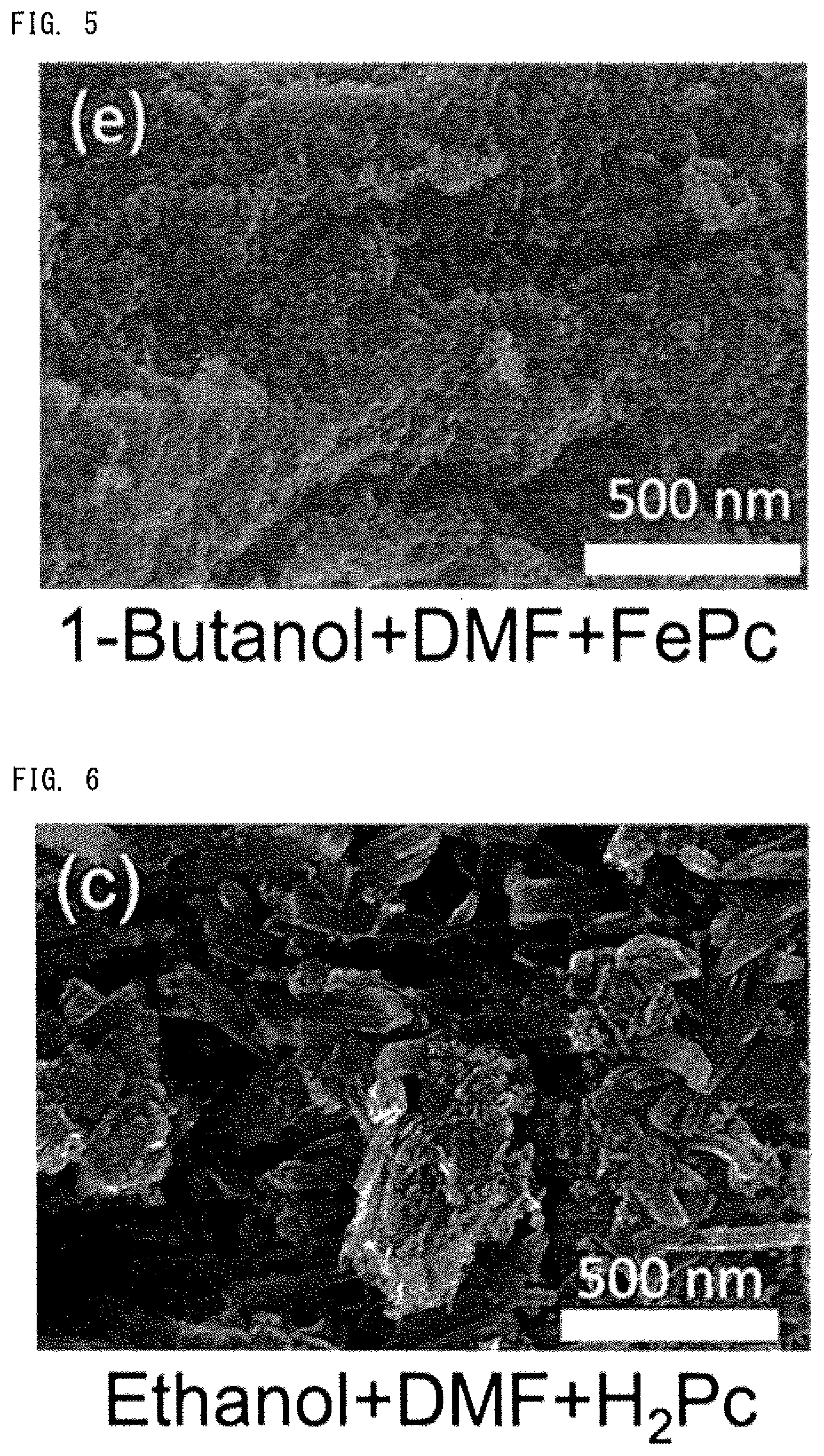
[0014] FIG. 5 A scanning electron microscopy image of the residue present in solution 3 after irradiation with plasma.
[0015] FIG. 6 A scanning electron microscopy image of the residue present in solution 4 after irradiation with plasma.
[0016] FIG. 7 A scanning electron microscopy image of the residue present in solution 5 after irradiation with plasma.
[0017] FIG. 8 A scanning electron microscopy image of the residue present in solution 6 after irradiation with plasma.
[0018] FIG. 9 A scanning electron microscopy image (enlarged view) of the sheet-form residue formed from solution 1.
[0019] FIG. 10 A transmission electron microscopy image of the sheet-form residue produced from solution 1.
[0020] FIG. 11 A graph of a Raman spectrum of the residue present in solution 1 after irradiation with plasma.
[0021] FIG. 12 A graph of a Raman spectrum of the residue present in solution 2 after irradiation with plasma.
[0022] FIG. 13 A graph of a Raman spectrum of the residue present in solution 3 after irradiation with plasma.
[0023] FIG. 14 A graph of a Raman spectrum of the residue present in solution 4 after irradiation with plasma.
[0024] FIG. 15 A graph of a Raman spectrum of the residue present in solution 5 after irradiation with plasma.
[0025] FIG. 16 A graph of a Raman spectrum of the residue present in solution 6 after irradiation with plasma.
[0026] FIG. 17 A graph of an emission spectrum of plasma.
[0027] FIG. 18 A schematic configuration of a rotating electrode apparatus.
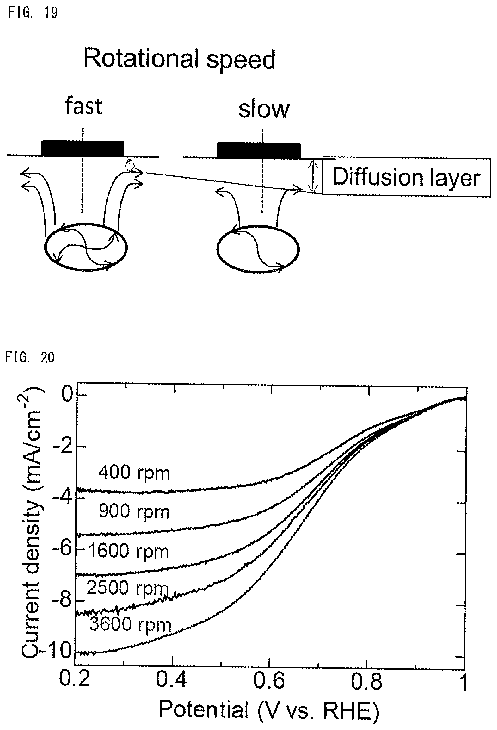
[0028] FIG. 19 A schematic diagram conceptually showing the relationship between the rotation rate of the working electrode and the thickness of the diffusion layer in water.
[0029] FIG. 20 A graph showing the relationship between the potential of the working electrode and current density.
[0030] FIG. 21 A graph showing the relationship between the potential of the working electrode and the current density, when ethanol is used as an alcohol.
[0031] FIG. 22 A graph for determining the number of electrons involved in reaction.
MODES FOR CARRYING OUT THE INVENTION
[0032] Next will be described specific embodiments of the carbon nanosheet production method employing a plasma generator and the carbon nanosheet produced through the method.
First Embodiment
1. Carbon Nanosheet
[0033] FIG. 1 schematically shows the structure of a carbon nanosheet CS1. As shown in FIG. 1, the carbon nanosheet CS1 is in the form of sheet. However, an actual carbon nanosheet product has a structure in which a plurality of carbon nanosheets CS1 are clustered.
[0034] The side length W1 of the carbon nanosheet CS1 is, for example, 0.5 .mu.m to 2.5 .mu.m. In some cases, a carbon nanosheet CS1 having a side length of 1 .mu.m to 2 .mu.m may be produced. The sheet thickness T1 of the carbon nanosheet CS1 is, for example, 0.7 nm to 10 nm. However, needless to say, a carbon nanosheet CS1 having a thickness falling outside the range may also be produced.
[0035] The carbon nanosheet CS1 contains iron atoms. As mentioned hereinbelow, the iron atoms originate from a raw material including iron atoms. Conceivably, the carbon nanosheet CS1 has an iron-nitrogen bond. As mentioned hereinbelow, the iron-nitrogen bond originates from a raw material having an iron-nitrogen bond. Also, the carbon nanosheet CS1 conceivably has a CN bond. As mentioned hereinbelow, CN radicals are generated under electric discharge.
2. Characteristics of Carbon Nanosheet
[0036] The carbon nanosheet CS1 exhibits an excellent catalytic activity for serving as a fuel cell catalyst. Therefore, the carbon nanosheet CS1 is a promising alternative for a platinum-based fuel cell catalyst. Details will be described in another section.
3. Plasma Generator
[0037] FIG. 2 is a schematic structure of a plasma generator 100 employed in the first embodiment. The plasma generator 100 is employed for producing the carbon nanosheet CS1 shown in FIG. 1. The plasma generator 100 has a first electrode structure 110, a second electrode structure 120, a voltage-applying unit 130, a container 140, a gas supply inlet 151, and a gas discharge outlet 152.
[0038] The first electrode structure 110 has a first electrode 111 and an electrically insulating member 112. The first electrode 111 is a rod-shape electrode including an end portion 111a. The first electrode 111 is made of a material such as sintered graphite. Alternatively, the material of the first electrode 111 may be a metal or an alloy. The electrically insulating member 112 covers at least a portion of the first electrode 111 other than the end portion 111a. That is, the end portion 111a of the first electrode 111 is exposed without being covered with the electrically insulating member 112. Within the conductive portion of the first electrode structure 110, only the end portion 111a of the first electrode 111 is exposed to the inside of the container 140.
[0039] The second electrode structure 120 has a second electrode 121, an electrically conductive member 122, and an electrically insulating member 123. The second electrode 121 is a rod-shape electrode. The second electrode 121 has a lateral surface 121a which faces the end portion 111a of the first electrode 111. The second electrode 121 is made of a material such as sintered graphite. Alternatively, the material of the second electrode 121 may be a metal or an alloy. The electrically conductive member 122 is electrically connected to the second electrode 121. The material of the electrically conductive member 122 may be any of a carbon material, a metal, and an alloy. The electrically insulating member 123 covers the electrically conductive member 122. The second electrode 121 is exposed without being covered with the electrically insulating member 123. As a result, within the conductive portion of the second electrode structure 120, only the second electrode 121 is exposed to the inside of the container 140.
[0040] The voltage-applying unit 130 is adapted to apply a voltage between the first electrode 111 and the second electrode 121. The voltage is, for example, 9 kV, and the frequency is, for example, 60 Hz.
[0041] The container 140 is disposed so as to accommodate at least a part of the first electrode structure 110 and a part of the second electrode structure 120, and liquid L1. As mentioned hereinbelow, the liquid L1 is a solution mixture prepared by mixing a solution of an iron atom-containing compound dispersed in a solvent with an alcohol. The container 140 has a container body 141 and a lid 142.
[0042] The gas supply inlet 151 is adapted to supply gas into the inner space of the container 140. Thus, in a specific mode, the gas supply inlet 151 is connected to a gas cylinder storing argon or the like. Preferably, a mass flow controller or the like is disposed between the gas supply inlet 151 and the gas cylinder.
[0043] The gas discharge outlet 152 is adapted to discharge gas present in the inner space of the container 140. Thus, in a specific mode, the gas discharge outlet 152 may be connected to an exhauster such as a vacuum pump.
4. Discharging Electricity in Plasma Generator
[0044] As shown in FIG. 2, in operation, the liquid L1 is placed in the container body 141. The liquid L1 is supplied until the second electrode 121 is completely immersed in the liquid L1. At this timing, the first electrode 111 is opposed to the second electrode 121 via the liquid surface of liquid L1. The distance between the first electrode 111 and the liquid surface of the liquid L1 is, for example, 0.01 mm to 10 mm. The distance between the second electrode 121 and the liquid surface of liquid L1 is, for example, 0.01 mm to 20 mm. These values are given merely as standard examples, and other values may be acceptable.
[0045] Next, a voltage is applied between the first electrode 111 and the second electrode 121. During voltage application, electric discharge occurs between the end portion 111a of the first electrode 111 and the lateral surface 121a of the second electrode 121. More specifically, the electric discharge occurs between the uppermost (the nearest to the end portion 111a of the first electrode 111) portion of the lateral surface 121a of the second electrode 121 and the end portion 111a. Since the electrically conductive member 122 is covered with the electrically insulating member 123, electric discharge does not occur directly between the first electrode 111 and the electrically conductive member 122.
[0046] Notably, during electric discharge, lightning from the end portion 111a of the first electrode 111 reaches the lateral surface 121a of the second electrode 121.
5. Carbon Nanosheet Production Method
5-1. Solution Mixture Production Step
[0047] First, a solution of an iron atom-containing compound dispersed in a solvent is prepared. In this case, the iron atom-containing compound is an organic compound such as iron phthalocyanine. Iron phthalocyanine has an Fe--N bond but no Fe--C bond. That is, iron phthalocyanine is a metallorganic compound which has a metal-nitrogen bond but no metal-carbon bond.
[0048] The solvent is preferably an organic solvent, since organic solvents can sufficiently dissolve iron phthalocyanine or a similar compound and are highly compatible with alcohol. Examples of the solvent include N,N-dimethylformamide (DMF) and tetrahydrofuran (THF).
[0049] Subsequently, the thus-prepared solution is mixed with an alcohol, to thereby prepare a solution mixture. Examples of the alcohol include ethanol, propanol, and butanol. Needless to say, other alcohols may also be acceptable.
[0050] In the above-described step, the solution mixture is prepared by mixing an alcohol with a solution containing an iron atom-containing compound which is dispersed in a solvent.
[0051] The thus-prepared solution mixture is poured into the container body 141 of the container 140. Thus, the second electrode 121 is located in the solution mixture.
5-2. Plasma Radiation Step
[0052] Subsequently, argon is supplied through the gas supply inlet 151, and the gas present in the container 140 is discharged through the gas discharge outlet 152. The operation is continued until the argon gas concentration of the internal atmosphere of the container 140 increases to a sufficiently high level. Then, a voltage is applied between the first electrode 111 and the second electrode 121, whereby electric discharge occurs between the end portion 111a of the first electrode 111 and the lateral surface 121a of the second electrode 121.
[0053] Thus, the first embodiment employs the container 140 for accommodating the solution mixture, the first electrode 111 located in the gas phase, and the second electrode 121 placed in the solution mixture. Through application of a voltage between the first electrode 111 and the second electrode 121, electric discharge is caused to occur at the gas-liquid interface. While the interior of the container 140 is purged with noble gas, the solution mixture is irradiated with plasma. The plasma density during irradiation is 3.times.10.sup.14 cm.sup.-3 to 7.times.10.sup.14 cm.sup.-3. In the gas phase, CN radicals and CH radicals are generated. The amount of CH radicals is not significant.
[0054] Thus, in this step, the solution mixture is irradiated with plasma, to thereby produce a carbon nanosheet. The internal pressure of the container 140 may be an atmospheric or reduced pressure. As a result, a carbon nanosheet is formed in the solution mixture.
6. Role of Iron
6-1. Iron Atoms in the Solvent of the First Embodiment
[0055] The solution mixture contains a solution in which an iron atom-containing compound is dispersed. Conceivably, the iron atom present in the Fe-containing compound virtually serves as a catalyst in production of a carbon nanosheet.
6-2. Carbon Material and Iron in Prior Art
[0056] In some conventional techniques, iron serves as a catalyst in formation of a carbon material. For example, Patent Document 1 discloses a technique in which a carbon nanotube is formed from starting points of growth, which is iron serving as a catalytic metal. Needless to say, carbon nanotube is a tube-form carbon material. According to such a conventional technique, a tube-form carbon structure can be produced. However, difficulty is encountered in producing a sheet-form carbon structure of the first embodiment.
7. Effects of the First Embodiment
[0057] In the first embodiment, the sheet-form carbon nanosheet CS1 can be produced. The carbon nanosheet CS1 is a carbon material differing from a carbon nanotube.
[0058] In the case where at least one of the first electrode 111 and the second electrode 121 is made of a carbon material, carbon atoms may be transferred to the solution mixture. In the case where at least one of the first electrode 111 and the second electrode 121 is made of a metal or alloy, the metal or alloy may be transferred to the solution mixture.
[0059] When plasma is caused to generate at the gas-liquid interface, active species are generated in both the gas phase and the liquid phase. These active species may be used in the reaction for producing a carbon nanosheet. Generally, radicals originating from the gas (atmosphere gas) are generated in the gas phase, and radicals originating from the liquid (solution mixture) are generated in the liquid phase. In the first embodiment, both active species generated in the gas phase and those generated in the liquid phase may be used in the reaction. Since the interior of the container 140 has been purged with noble gas, substantially no active species derived from air are generated.
8. Modification
8-1. Iron Atom-Containing Compound
[0060] In the first embodiment, the iron atom-containing compound is, for example, iron phthalocyanine. Alternatively, the iron atom-containing compound may be hemin. Both iron phthalocyanine and hemin are organic compounds each containing an iron atom. Also, hemin has an Fe--N bond, but has no Fe--C bond. Therefore, when hemin is used, the carbon nanosheet CS1 may also be formed.
8-2. Plasma Gas
[0061] In the first embodiment, argon is supplied through the gas supply inlet 151. However, an oxygen-free gas other than argon may also be used. The oxygen-free gas other than argon is a gas having an oxygen gas content (by volume) of 1% or less. Examples of the gas include noble gases such as He and Ne, and nitrogen. In order to prevent reaction with the solution mixture, the gas supplied through the gas supply inlet 151 is preferably a noble gas.
8-3. Plasma Generator
[0062] A plasma apparatus other than the plasma generator 100 shown in FIG. 2 may also be employed.
8-4. Combination
[0063] Any combination of the aforementioned modifications may be employed.
EXAMPLES
Experiment 1
1. Plasma Apparatus
[0064] The plasma apparatus 100 shown in FIG. 2 was employed. The first electrode 111 was made of graphite and had a diameter of 3 mm. The first electrode 111 was located at a position 1 mm above the liquid surface of the solution mixture. The second electrode 121 was made of graphite. The second electrode 121 was located at a position 9 mm below the liquid surface of the solution mixture.
2. Solution Mixture
[0065] Solutions (including solution mixtures) shown in Table 1 were used. In Table 1, DMF denotes N,N-dimethylformamide, FePc denotes iron phthalocyanine, and H.sub.2Pc denotes phthalocyanine.
[0066] In preparation of solution 1, iron phthalocyanine was dispersed in N,N-dimethylformamide, to thereby form a dispersion. The dispersion operation was carried out for 30 minutes by means of a homogenizer. To the dispersion (40 mL), an alcohol (160 mL) was added, to thereby form a solution mixture. The solution mixture was subjected to dispersion treatment for 10 minutes. Other solutions were produced in the same manner.
TABLE-US-00001 TABLE 1 Solution Alcohol Additive Solution 1 ethanol DMF + FePc Solution 2 propanol DMF + FePc Solution 3 butanol DMF + FePc Solution 4 ethanol DMF + H.sub.2Pc Solution 5 ethanol DMF Solution 6 ethanol
3. Method of Experiment
[0067] The solution mixture (200 mL) was put into the container body 141 of the container 140. Ar gas was supplied through the gas supply inlet 151 at a flow rate of 6 slm. Under the thus-provided conditions, a voltage was applied between the first electrode 111 and the second electrode 121 for 5 minutes. AC frequency was 60 Hz. Thereafter, the solution mixture was filtrated through a filtration membrane, to thereby recover a product (residue).
4. Results of Experiments
4-1. Visual Observation
[0068] Table 2 shows the results.
TABLE-US-00002 TABLE 2 Solution Alcohol Additive Sheet Solution 1 ethanol DMF + FePc .largecircle..largecircle. Solution 2 propanol DMF + FePc .largecircle. Solution 3 butanol DMF + FePc .largecircle. Solution 4 ethanol DMF + H.sub.2Pc X Solution 5 ethanol DMF X Solution 6 ethanol X
[0069] Through irradiation of solution 1 with plasma, a residue containing sheet-like matter (side length: about 0.5 .mu.m to about 2.5 .mu.m) was yielded. Through irradiation of solution 2 or 3 with plasma, a residue containing sheet-like matter was yielded. The sheet-like matter was slightly smaller than that obtained from solution 1. Through irradiation of any one of solutions 4 to 6 with plasma, a residue was yielded. However, no sheet-like matter having a side length greater than 0.5 .mu.m was identified in the residue through scanning electron microscopy. In all cases, the sheet-like matter was confirmed through visual observation.
4-2. Microscopy Image
[0070] FIG. 3 is a scanning electron microscopy image of the residue present in solution 1 after irradiation with plasma. FIG. 4 is a scanning electron microscopy image of the residue present in solution 2 after irradiation with plasma. FIG. 5 is a scanning electron microscopy image of the residue present in solution 3 after irradiation with plasma. FIG. 6 is a scanning electron microscopy image of the residue present in solution 4 after irradiation with plasma. FIG. 7 is a scanning electron microscopy image of the residue present in solution 5 after irradiation with plasma. FIG. 8 is a scanning electron microscopy image of the residue present in solution 6 after irradiation with plasma.
[0071] FIG. 9 is a wide-view scanning electron microscopy image of the sheet-form residue formed from solution 1. In the figure, sheet-like fragments were clustered. FIG. 10 is a transmission electron microscopy image of the sheet-form residue produced from solution 1. In the figure, a residue having a form of a bent sheet was observed. As shown in FIG. 10, the residue is a sheet-like matter.
4-3. Raman Shift
[0072] FIG. 11 is a graph of a Raman spectrum of the residue present in solution 1 after irradiation with plasma. FIG. 12 is a graph of a Raman spectrum of the residue present in solution 2 after irradiation with plasma. FIG. 13 is a graph of a Raman spectrum of the residue present in solution 3 after irradiation with plasma. FIG. 14 is a graph of a Raman spectrum of the residue present in solution 4 after irradiation with plasma. FIG. 15 is a graph of a Raman spectrum of the residue present in solution 5 after irradiation with plasma. FIG. 16 is a graph of a Raman spectrum of the residue present in solution 6 after irradiation with plasma.
[0073] As shown in each of FIGS. 11 to 16, D band (1340 cm.sup.-1), G band (1580 cm.sup.-1), D.quadrature. band (1620 cm.sup.-1), and 2D band (2700 cm.sup.-1) were observed. There was no substantial difference in Raman shift profile among the Raman spectra of FIGS. 11 to 16. However, the intensity of 2D band in FIG. 14 is lower than the intensities of other bands such as D band. FIGS. 11 to 16 suggest that each residue is formed of a certain carbon material. Thus, the sheet-like residue is thought to be a carbon material structure. That is, the sheet-like residue is thought to be a carbon nanosheet. A residue of non-sheet-like matter is thought to be formed of a carbon nanomaterial other than a carbon nanosheet.
4-4. Plasma-Mediated Products
[0074] FIG. 17 is a graph of an emission spectra of plasma. As shown in FIG. 17, peaks attributed to Fe or C (250 nm), OH (310 nm), CN (390 nm), CH (430 nm), H (488 nm, 656 nm), and C.sub.2 (474 nm, 516 nm, and 564 nm) were observed. At least one of the plasma-mediated products is involved in formation of the carbon nanosheet CS1.
Experiment 2
[0075] Next, an application field of the carbon nanosheet was investigated. Specifically, a catalytic property of the carbon nanosheet was evaluated.
1. Oxygen-Reduction Reaction
[0076] Oxygen-reduction reaction includes the following two reaction paths:
O.sub.2+2H.sup.++2e.sup.-.fwdarw.H.sub.2O.sub.2 (1)
O.sub.2+4H.sup.++4e.sup.-.fwdarw.2H.sub.2O (2).
[0077] Equation (1) is a 2-electron reaction in which 2 electrons are involved. Equation (2) is a 4-electron reaction in which 4 electrons are involved. From the viewpoint of gaining large current, predominance of 4-electron reaction is preferred in a fuel cell.
2. Apparatus
[0078] FIG. 18 is a schematic configuration of a rotating electrode apparatus. The rotating electrode apparatus is operated in hydrodynamic voltammetry (HDV), to thereby determine which of the 2-electron reaction and the 4-electron reaction is predominant. The apparatus includes a container body for accommodating an electrolyte, a working electrode, a counter electrode, a reference electrode, and a potentiostat. The working electrode is a rotating electrode. The potentiostat monitors the potential of the working electrode with respect to the reference electrode, and a current flowing between the working electrode and the counter electrode.
3. Principle of Measurement
[0079] FIG. 19 is a schematic diagram conceptually showing the relationship between the rotation rate of the working electrode and the thickness of the diffusion layer in water. As shown in FIG. 19, the higher the rotation speed of the rotating electrode, the thinner the diffusion layer. In other words, the lower the rotation speed, the thicker the diffusion layer.
[0080] FIG. 20 is a graph showing the relationship between the potential of the working electrode and the current density. In FIG. 20, the horizontal axis represents the working electrode potential with respect to the reference electrode, and the vertical axis represents the current density of the current flowing between the working electrode and the counter electrode. As is clear from FIG. 20, the higher the rotation speed, the greater the absolute value of current density. In other words, the lower the rotation speed, the smaller the absolute value of current density.
[0081] The current density of the diffusion current flowing from the working electrode satisfies the following relationship (Koutecky-Levich formula):
(j).sup.-1=(j.sub.k).sup.-1+(B.omega..sup.1/2).sup.-1 (3)
B=0.2nFDo.sup.2/3.upsilon..sup.-1/6Co (4)
F: Faraday constant (96,485 Cmol.sup.-1) Do: Diffusion coefficient of O.sub.2 (1.9.times.10.sup.-5 cm.sup.2/s) .upsilon.: Kinematic viscosity (0.01 cm.sup.2/s) Co: O.sub.2 bulk density (1.2.times.10.sup.-6 molcm.sup.-3) n: Number of electrons involved in reaction
[0082] The number of electrons involved in reaction can be derived from equations (3) and (4).
4. Measurement Conditions
[0083] Iron phthalocyanine was used as an iron atom-containing compound. N,N-dimethylformamide (DMF) was used as a solvent. Ethanol or 1-butanol was used as an alcohol.
[0084] A working electrode made of glassy carbon and a platinum wire counter electrode were employed. A reference electrode made of an Ag/AgCl electrode was employed in the case of an alkaline medium, and a reversible hydrogen reference electrode was employed in the case of an acidic medium. The alkaline medium was 0.1M KOH, and the acidic medium was 0.1M HClO.sub.4. The working electrode was rotated at 400 rpm, 900 rpm, 1,600 rpm, and 2,500 rpm.
5. Results of Measurement
[0085] FIG. 21 is a graph showing the relationship between the potential of the working electrode and the current density, when ethanol is used as the alcohol. In FIG. 20, the horizontal axis represents the potential of the working electrode with respect to the reference electrode in an alkaline medium, and the vertical axis represents the current density of the current flowing between the working electrode and the counter electrode. As shown in FIG. 21, the current density profile varied in response to the rotation rate of the working electrode.
[0086] FIG. 22 is a graph for determining the number of electrons involved in reaction. In FIG. 22, the horizontal axis represents the angular speed of the working electrode to the power -1/2, and the vertical axis represents the reciprocal of current density. As shown in FIG. 22, the reciprocal of current density was plotted in a linear manner with respect to the horizontal axis both in the cases of ethanol and 1-butanol, indicating that application of equations (3) and (4) was appropriate.
6. Catalytic Property of Carbon Nanosheet
[0087] Table 3 shows the number of electrons involved in reaction, when several alcohols were used. As shown in Table 3, when 1-butanol was used, the number of electrons involved in reaction was found to be 2.44, whereas when ethanol was used, the number was found to be 4.06. Thus, when ethanol was used as an alcohol, 4-electron reaction was considerably predominant. In other words, the carbon nanosheet produced with ethanol as an alcohol can serve as an excellent catalyst for fuel cells.
TABLE-US-00003 TABLE 3 Alcohol No. of electrons in reaction ethanol 4.06 1-butanol 2.44
INDUSTRIAL APPLICABILITY
[0088] The carbon nanosheet having the aforementioned characteristics is used as, for example, a catalyst for fuel cells. Also, the carbon nanosheet may possibly be employed as an electrode in a lithium ion secondary battery or in a polymer electrolyte fuel cell.
ADDITIONAL REMARKS
[0089] The carbon nanosheet production method according to the first aspect comprises a step of mixing a solution of an iron atom-containing compound dispersed in a solvent with an alcohol, to thereby prepare a solution mixture; and a step of irradiating the solution mixture with plasma, to thereby produce a carbon nanosheet.
[0090] In the carbon nanosheet production method according to a second aspect, the step of irradiating the solution mixture with plasma employs a first electrode in a gas phase and a second electrode in the solution mixture. Through application of a voltage between the first electrode and the second electrode, electric discharge is caused to occur at the gas-liquid interface.
[0091] In the carbon nanosheet production method according to a third aspect, in the step of irradiating the solution mixture with plasma, electric discharge is caused to occur between an end portion of the first electrode and a lateral surface of the second electrode.
[0092] In the carbon nanosheet production method according to a fourth aspect, at least one of the first electrode and the second electrode is made of a carbon material.
[0093] In the carbon nanosheet production method according to a fifth aspect, in the step of irradiating the solution mixture with plasma, CN radicals are generated.
[0094] In the carbon nanosheet production method according to a sixth aspect, in the step of irradiating the solution mixture with plasma, a container for accommodating the solution mixture is employed. While the interior of the container is purged with noble gas, the solution mixture is irradiated with plasma.
[0095] In the carbon nanosheet production method according to a seventh aspect, the iron atom-containing compound is an organic compound.
[0096] In the carbon nanosheet production method according to an eighth aspect, the organic compound has a metal-nitrogen bond but no metal-carbon bond.
[0097] In the carbon nanosheet production method according to a ninth aspect, the alcohol is ethanol.
[0098] In the carbon nanosheet production method according to a tenth aspect, the solvent is an organic solvent.
[0099] In the carbon nanosheet production method according to an eleventh aspect, in the step of irradiating the solution mixture with plasma, the solution mixture is irradiated with plasma at a plasma density of 3.times.10.sup.14 cm.sup.-3 to 7.times.10.sup.14 cm.sup.-3.
[0100] In the carbon nanosheet production method according to a twelfth aspect, the carbon nanosheet has a side having a length of 0.5 .mu.m to 2.5 .mu.m.
[0101] The carbon nanosheet according to a thirteenth aspect has a sheet form. The sheet has a side having a length of 0.5 .mu.m to 2.5 .mu.m and a thickness of 0.7 nm to 10 nm.
[0102] In the carbon nanosheet according to a fourteenth aspect, a plurality of carbon nanosheets are clustered.
[0103] The carbon nanosheet according to a fifteenth aspect contains an iron atom.
DESCRIPTION OF THE REFERENCE NUMERALS
[0104] CS1 . . . carbon nanosheet [0105] 100 . . . plasma generator [0106] 110 . . . first electrode structure [0107] 111 . . . first electrode [0108] 111a . . . end portion [0109] 112 . . . electrically insulating member [0110] 120 . . . second electrode structure [0111] 121 . . . second electrode [0112] 121a . . . lateral surface [0113] 122 . . . electrically conductive member [0114] 123 . . . electrically insulating member [0115] 130 . . . voltage-applying unit [0116] 140 . . . container [0117] 141 . . . container body [0118] 142 . . . lid [0119] 151 . . . gas supply inlet [0120] 152 . . . gas discharge outlet
* * * * *
D00000
D00001
D00002
D00003
D00004
D00005
D00006
D00007
D00008
D00009
D00010
D00011
XML
uspto.report is an independent third-party trademark research tool that is not affiliated, endorsed, or sponsored by the United States Patent and Trademark Office (USPTO) or any other governmental organization. The information provided by uspto.report is based on publicly available data at the time of writing and is intended for informational purposes only.
While we strive to provide accurate and up-to-date information, we do not guarantee the accuracy, completeness, reliability, or suitability of the information displayed on this site. The use of this site is at your own risk. Any reliance you place on such information is therefore strictly at your own risk.
All official trademark data, including owner information, should be verified by visiting the official USPTO website at www.uspto.gov. This site is not intended to replace professional legal advice and should not be used as a substitute for consulting with a legal professional who is knowledgeable about trademark law.