Self-standing Packing Bag With Spout
KUGE; Raizo ; et al.
U.S. patent application number 16/959502 was filed with the patent office on 2021-02-25 for self-standing packing bag with spout. The applicant listed for this patent is HOSOKAWA YOKO CO., LTD.. Invention is credited to Raizo KUGE, Tomonari SHINOHARA.
| Application Number | 20210053737 16/959502 |
| Document ID | / |
| Family ID | 1000005209187 |
| Filed Date | 2021-02-25 |


View All Diagrams
| United States Patent Application | 20210053737 |
| Kind Code | A1 |
| KUGE; Raizo ; et al. | February 25, 2021 |
SELF-STANDING PACKING BAG WITH SPOUT
Abstract
In a self-standing packing bag with a spout of the present invention, a bottom section is formed by a bottom member that is half folded at a fold line and is attached to an inside of a lower portion of the trunk section such that the fold line faces upward, an extending direction of the fold line of the bottom section and a closing direction of an upper end of the trunk section intersect each other on a horizontal projection plane, and side end portions of two regions of the bottom member divided by the fold line are planarly bonded to an inside of the trunk section in an overlapping state.
| Inventors: | KUGE; Raizo; (Hanno-shi, JP) ; SHINOHARA; Tomonari; (Iruma-gun, JP) | ||||||||||
| Applicant: |
|
||||||||||
|---|---|---|---|---|---|---|---|---|---|---|---|
| Family ID: | 1000005209187 | ||||||||||
| Appl. No.: | 16/959502 | ||||||||||
| Filed: | January 25, 2019 | ||||||||||
| PCT Filed: | January 25, 2019 | ||||||||||
| PCT NO: | PCT/JP2019/002500 | ||||||||||
| 371 Date: | July 1, 2020 |
| Current U.S. Class: | 1/1 |
| Current CPC Class: | B65D 75/5883 20130101; B65D 75/008 20130101; B65D 2231/001 20130101 |
| International Class: | B65D 75/58 20060101 B65D075/58; B65D 75/00 20060101 B65D075/00 |
Foreign Application Data
| Date | Code | Application Number |
|---|---|---|
| Feb 2, 2018 | JP | 2018-017413 |
Claims
1. A self-standing packing bag with a spout comprising: a trunk section which is formed in a cylindrical shape and of which an upper end is closed; a bottom section which is attached to a lower portion of the trunk section; and a spout which is attached to an upper end of the trunk section, wherein the bottom section is formed by a bottom member that is half folded at a fold line and is attached to an inside of the lower portion of the trunk section such that the fold line faces upward, wherein an extending direction of the fold line of the bottom section and a closing direction of the upper end of the trunk section intersect each other on a horizontal projection plane, and wherein side end portions of two regions of the bottom member divided by the fold line are planarly bonded to an inside of the trunk section in an overlapping state.
2. The self-standing packing bag with the spout according to claim 1, wherein the spout has a check valve function.
Description
TECHNICAL FIELD
[0001] The present invention relates to a self-standing packing bag with a spout.
[0002] Priority is claimed on Japanese Patent Application No. 2018-017413 filed on Feb. 2, 2018, the content of which is incorporated herein by reference.
BACKGROUND ART
[0003] As a bag formed of a soft packing material such as a plastic film, a self-standing bag, that is, a self-standing packaging bag (standing pouch) is known. As the self-standing packing bag, there is known a packing bag which is formed such that side end portions of a bottom member are sandwiched by side end portions of a trunk member while the half folded bottom member forming a bottom section is inserted into a lower portion of a cylindrical trunk section so that its fold line faces upward, the side end portions are heat-sealed, and their lower ends are heat-sealed over the entire circumference. In such a conventional self-standing packing bag, a closing direction of the upper end of the trunk section is generally parallel to the fold line of the bottom section. In such a self-standing packing bag, when the amount of the contents decreases, the distance between the horizontal facing surfaces of the film forming the trunk section gradually decreases to be in contact with each other and the horizontal thickness of the container is thinned so as to be flat. As a result, it is difficult to sufficiently secure self-standing ability. Here, various measures for improving self-standing ability of such a self-standing packing bag have been proposed from the past and as one of the measures, a packing bag shown in Patent Document 1 is known.
[0004] The standing pouch (the self-standing packing bag) of Patent Document 1 has a shape in which an extending direction of the fold line of the bottom section and an extending direction of a sealed spout of the upper end of the trunk section intersect each other on a horizontal projection plane. In the packing bag of Patent Document 1, since the directions of the spout of the trunk section and the bottom section are set as described above, the fold line of the bottom section extends in a direction different from the flat surface of the upper portion of the trunk section and the self-standing packing bag spreads three-dimensionally even when the distance between the facing surfaces of the facing films forming the trunk section in the upper portion of the trunk section decreases to be flat with a decrease in the amount of the contents. Accordingly, self-standing ability can be secured. Additionally, in the self-standing packing bag of Patent Document 1, when bonding the bottom section to the trunk section, the side end portion of the bottom section is sandwiched by the trunk member and is bonded from the outer surface side of the trunk section by heat-sealing or the like.
[0005] On the other hand, among the packaging bags, a soy sauce container formed of a soft packing material may have a check valve function at a spout to prevent external air from entering the container for the purpose of preventing oxidation and the like. In such a packing bag having the check valve function, when the amount of the contents decreases, external air does not enter. Accordingly, the internal volume decreases and hence a distance between the horizontal facing surfaces of the films forming the trunk section is narrowed to be in a close contact state. As a result, it is more difficult to maintain self-standing ability compared to the packing bag without the check valve function. Here, Patent Document 2 discloses a self-standing pouch having a check valve function, which is a self-standing pouch having a double structure of an inner bag formed of a synthetic resin film and filled with contents and an outer bag having a side seal portion, capable of standing on its bottom, formed of a synthetic resin film, and containing the inner bag. Further, Patent Document 3 discloses a liquid-filled packaging structure having a double structure of a non-self-standing liquid-filled packaging body and a self-standing packaging bag formed of a laminated film.
CITATION LIST
Patent Literature
[0006] [Patent Document 1]
[0007] Japanese Unexamined Patent Application, First Publication No. 2001-247135 [0008] [Patent Document 2]
[0009] Japanese Unexamined Patent Application, First Publication No. 2015-006891 [0010] [Patent Document 3]
[0011] Japanese Unexamined Patent Application, First Publication No. 2010-018323
SUMMARY OF INVENTION
Technical Problem
[0012] In the self-standing packing bag disclosed in Patent Document 1, when bonding the bottom section to the trunk section, the side end portion of the bottom section is sandwiched by the trunk section and is bonded from the outer surface side of the trunk section by heat-sealing or the like to form the bonded portion. Then, there is a change in the width of the content container from the upper end of the joint. That is, the trunk section above the upper end of the bonded portion spreads over its full width with the contents contained therein, but in a portion provided with the bonded portion, that is, the lower portion of the trunk section provided with the bottom member, the bonded portion prevents the trunk section from spreading by the width of the bonded portion. As a result, when the internal pressure of the bag increases such as when the bag is dropped, the load of the contents is locally and largely applied to the upper end of the bonded portion. Accordingly, there is a problem that the bonded portion is broken and the bag is easily broken. Further, in a state in which the remaining amount of the contents is small, the contents are accumulated on the upper end of the bonded portion as described above and hence the contents cannot be discharged completely.
[0013] Further, in the self-standing pouch of Patent Document 2 and the liquid-filled packaging structure of Patent Document 3, since the inner bag filled with the contents does not have self-standing ability in the structure having the check valve function, the outer bag is allowed to secure self-standing ability by a double bag structure. However, due to the double structure, it is difficult to visually check a decrease in the amount of the contents from the outside. Further, there is a problem that the manufacture is difficult and the cost is high.
[0014] The present invention has been made in view of the above-described circumstances and an object of the present invention is to provide a self-standing packing bag with a spout which is formed of a soft and thin material such as a single-structure laminated film, can reliably and sufficiently secure self-standing ability, and prevents an easy breakage of an upper end in a bonded portion between a trunk section and a bottom section side end portion.
Solution to Problem
[0015] A self-standing packing bag with a spout of the present invention includes: a trunk section which is formed in a cylindrical shape and of which an upper end is closed; a bottom section which is attached to a lower portion of the trunk section; and a spout which is attached to an upper end of the trunk section, wherein the bottom section is formed by a bottom member that is half folded at a fold line and is attached to an inside of the lower portion of the trunk section such that the fold line faces upward, wherein an extending direction of the fold line of the bottom section and a closing direction of the upper end of the trunk section intersect each other on a horizontal projection plane, and wherein side end portions of two regions of the bottom member divided by the fold line are planarly bonded to an inside of the trunk section in an overlapping state.
[0016] In the self-standing packing bag with the spout of the present invention, since the extending direction of the fold line of the bottom section and the closing direction of the upper end of the trunk section intersect each other on the horizontal projection plane, self-standing ability can be secured since the fold line of the bottom section spreads in a direction different from the upper portion of the trunk section even when a gap between the facing surfaces of the trunk section is gradually narrowed from above so as to be flat with a decrease in the amount of the contents.
[0017] Further, in the self-standing packing bag with the spout of the present invention, a bonded portion which is planarly bonded to the inner surface of the trunk section is formed while the side end portions of two regions of the bottom member overlap each other. With this structure, since the lower portion of the trunk section does not have the bonded portion which prevents the spreading width of the trunk section, it is possible to prevent the load of the contents from being locally applied to the upper end of the bonded portion even when the internal pressure of the bag increases such as when the bag is dropped and to prevent the breakage from the bonded portion in advance. Further, even in a state in which the amount of the contents is small, it is possible to prevent a problem that the contents are accumulated on the upper end of the bonded portion and the contents cannot be completely discharged.
[0018] Further, in the self-standing packing bag with the spout of the present invention, the spout may have a check valve function.
[0019] In the self-standing packing bag with the spout with such a check valve function, air is hardly introduced from the outside even when the bag is filled with contents such as soy sauce which is liable to be oxidized or deteriorated by contact with air and hence the oxidization or deterioration of the contents can be prevented. On the other hand, when the spout has the check valve function, in the conventional general packaging bags, adhesion between the facing surfaces of the trunk section is likely to occur due to an internal negative pressure with a decrease in the amount of contents and the trunk section is substantially flat. Accordingly, it is difficult to secure self-standing ability. For that reason, a container having a double structure was used in order to secure self-standing ability. However, since the extending direction of the fold line of the bottom section and the closing direction of the upper end of the trunk section intersect each other on the horizontal projection plane as described above, self-standing ability can be sufficiently secured only by the self-standing packing bag formed of a soft and thin material such as a single-structure laminated film without a double structure even when the amount of the contents decreases.
Effects of Invention
[0020] According to the self-standing packing bag with the spout of the present invention, sufficient self-standing ability can be secured even when the amount of the contents decreases. According to the self-standing packing bag with the spout of the present invention, at the same time, the load of the contents is not locally applied to the upper end of the bonded portion between the trunk section and the side end portion of the bottom member and the breakage from the bonded portion can be prevented in advance. According to the self-standing packing bag with the spout of the present invention, it is possible to prevent a problem that the contents are accumulated on the upper end of the bonded portion and the contents cannot be completely discharged even when the remaining amount of the contents is small. Further, even when the spout has the check valve function, self-standing ability can be secured by the self-standing packing bag formed of a single-structure laminated film or the like.
BRIEF DESCRIPTION OF DRAWINGS
[0021] FIG. 1 is a perspective view showing a. self-standing packing bag with a spout of a first embodiment of the present invention.
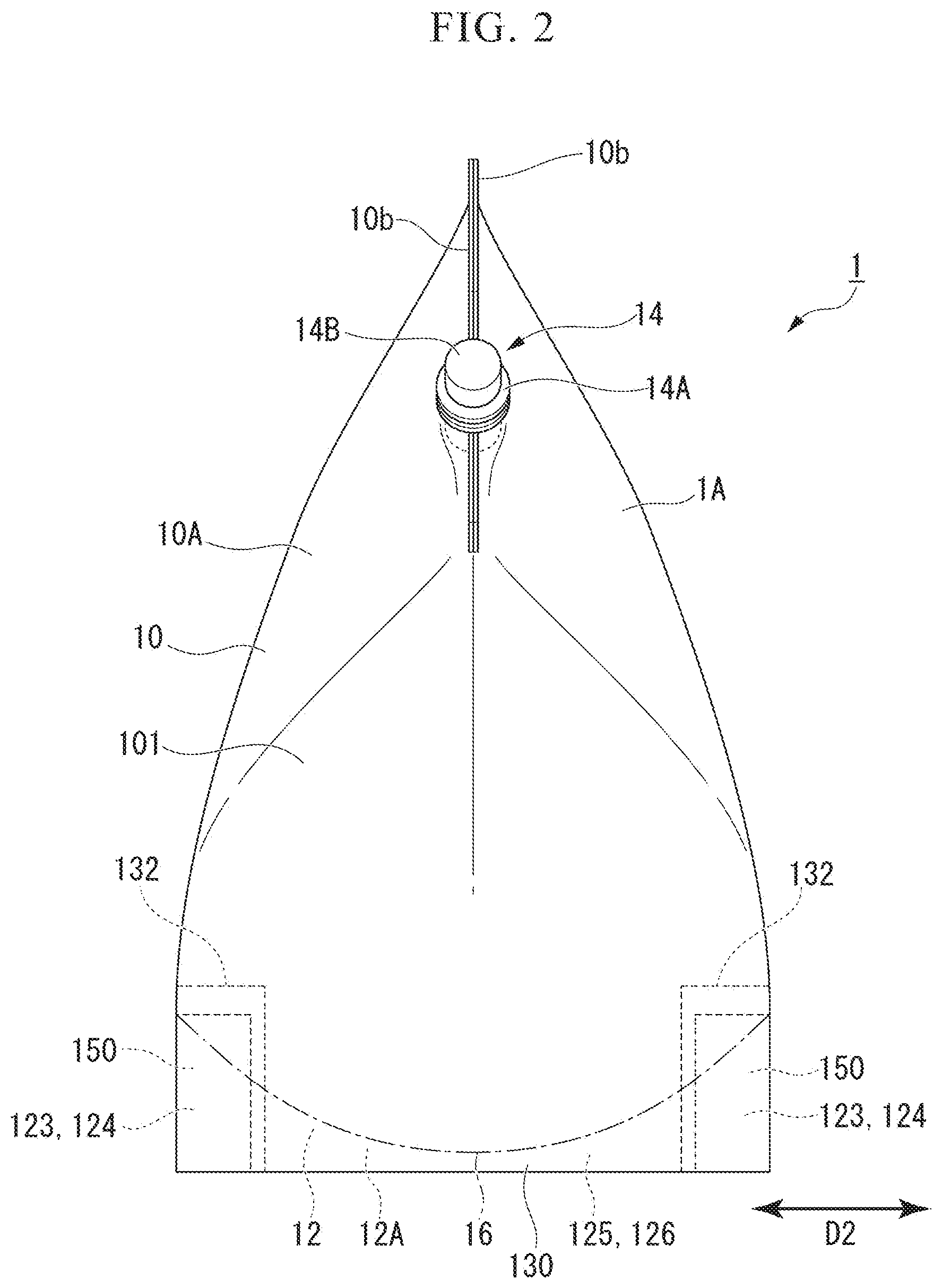
[0022] FIG. 2 is a front view of the self-standing packing bag with the spout of the embodiment.
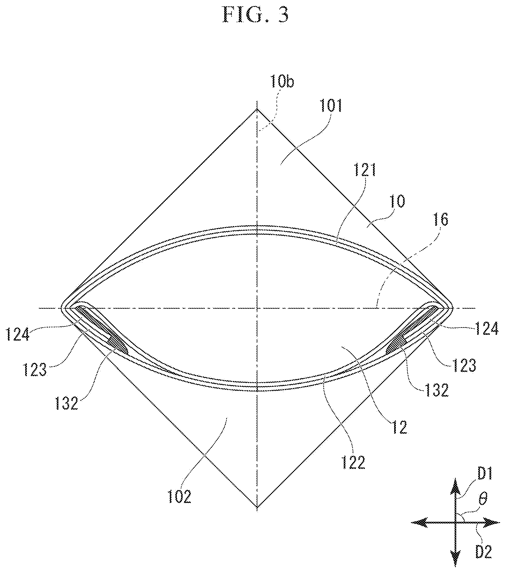
[0023] FIG. 3 is a bottom view of the self-standing packing bag with the spout of the embodiment.
[0024] FIG. 4A is a schematic view showing a method of folding a bottom member before bonding the bottom member to a trunk member in a self-standing packing bag manufacturing process of the embodiment.
[0025] FIG. 4B is a schematic view showing the method of folding the bottom member before bonding the bottom member to the trunk member in the self-standing packing bag manufacturing process of the embodiment.
[0026] FIG. 5 is a development view of the self-standing packing bag showing an example of a state in which the bottom member is bonded to the trunk member in the manufacturing process.
[0027] FIG. 6 is an enlarged cutaway perspective view showing the inside of the self-standing packing bag in a circled portion VI of FIG. 1.
[0028] FIG. 7 is a cross-sectional view showing an example of a spout of a second embodiment of the present invention.
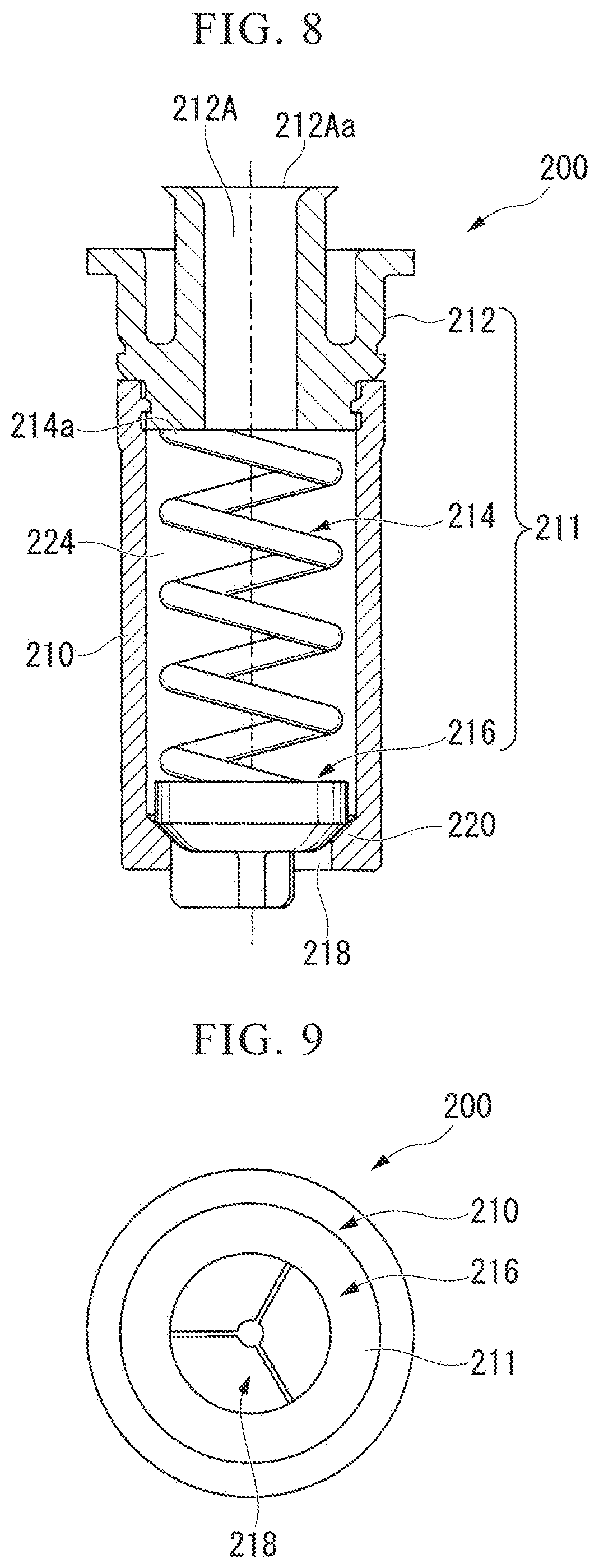
[0029] FIG. 8 is a longitudinal sectional view of a check valve incorporated in an exemplary spout of the second embodiment.
[0030] FIG. 9 is a bottom view of the check valve incorporated in the exemplary spout of the second embodiment.
[0031] FIG. 10A is a schematic view gradually showing a first half of an exemplary procedure of a method of folding a self-standing packing bag with a spout of the present invention.
[0032] FIG. 10B is a schematic view gradually showing the first half of the exemplary procedure of the method of folding the self-standing packing bag with the spout of the present invention.
[0033] FIG. 10C is a schematic view gradually showing the first half of the exemplary procedure of the method of folding the self-standing packing bag with the spout of the present invention.
[0034] FIG. 11A is a schematic view gradually showing a second half of the exemplary procedure of the method of folding the self-standing packing bag with the spout of the present invention.
[0035] FIG. 11B is a schematic view gradually showing the second half of the exemplary procedure of the method of folding the self-standing packing bag with the spout of the present invention.
[0036] FIG. 11C is a schematic view gradually showing the second half of the exemplary procedure of the method of folding the self-standing packing bag with the spout of the present invention.
DESCRIPTION OF EMBODIMENTS
[0037] Hereinafter, a self-standing packing bag with a spout of a first embodiment of the present invention will be described in detail with reference to FIGS. 1 to 6.
[0038] A self-standing packing bag with a spout 1 of this embodiment is shown in FIGS. 1 to 3.
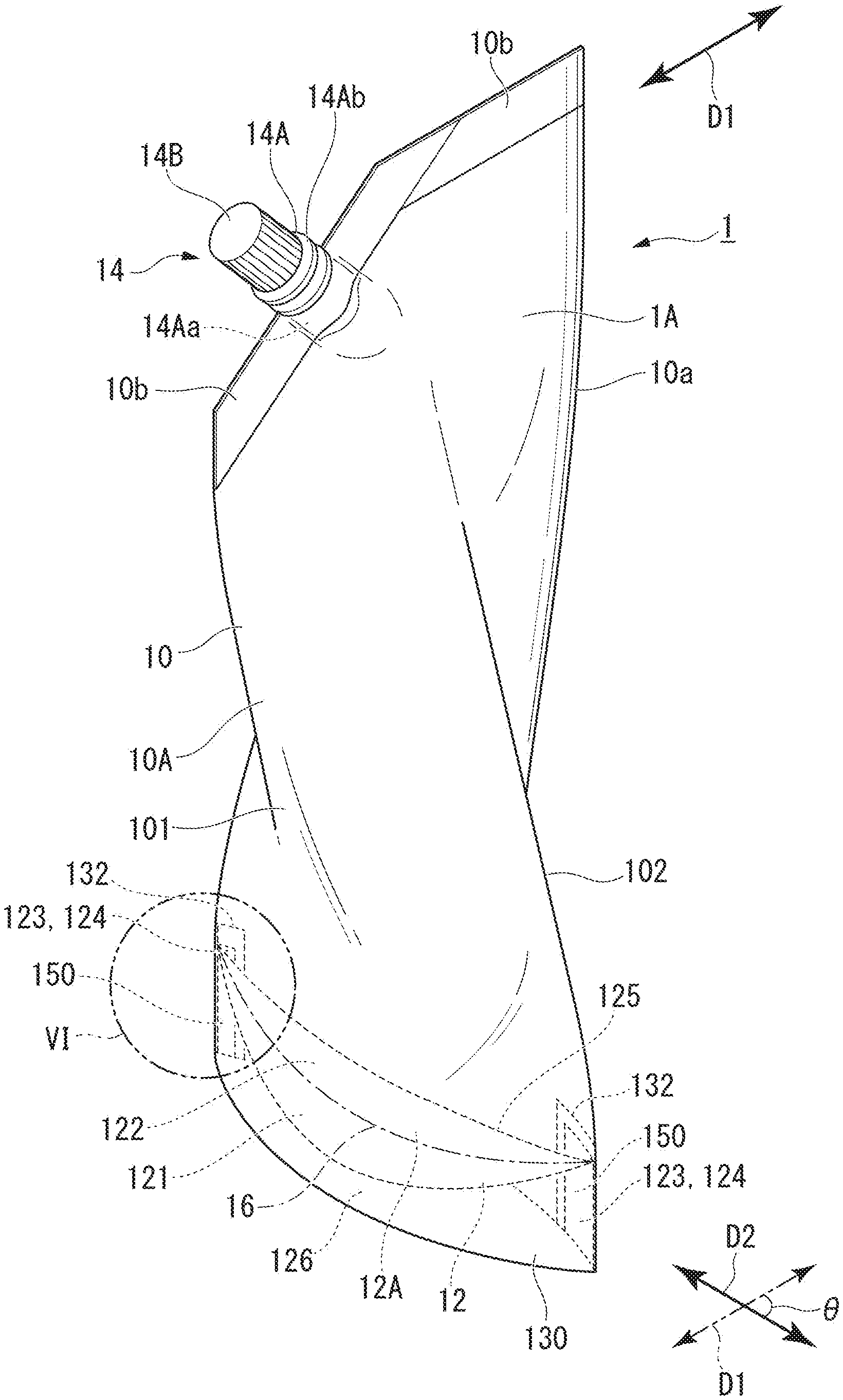
[0039] As shown in FIG. 1, the self-standing packing bag with the spout 1 of this embodiment includes a trunk section 10 which is formed in a cylindrical shape, a self-standing packing bag 1A which includes a bottom section 12 provided inside the trunk section 10 so as to close its lower portion, and a spout 14 which is provided in an upper end portion of the trunk section 10.
[0040] The trunk section 10 is formed by a trunk member 10A formed of a soft thin material (such as a film or a sheen such as a resin film. The thin material forming the trunk member 10A is preferably formed of a laminated film having at least a base material layer forming the outermost layer and a sealant layer forming the innermost layer and the following laminated films are exemplary examples.
[0041] As the base material layer of the trunk member 10A, a film having excellent printability and further having piercing strength, tensile strength, impact resistance, and the like is preferable. Examples of base material layer include polyethylene terephthalate, polypropylene, polyamide, ethylene vinyl alcohol copolymer, and the like and a biaxially stretched film or a uniaxially stretched film is preferable. Further, in order to impart a barrier property to oxygen and water vapor to these films, a vapor-deposited film obtained by vapor-depositing a metal such as aluminum or magnesium or an oxide such as silicon oxide, a coated film coated with a barrier coating agent such as polyvinylidene chloride, or the like may be used. The base material layer may be a single unit of the above-described films or a laminate thereof.
[0042] The sealant layer of the trunk member 10A is a layer that can be heated and melted to be heat-sealed within a temperature range that can maintain the shape of the base material layer. Examples of the material of the sealant layer include polyethylene such as high-density polyethylene, low-density polyethylene, and linear low-density polyethylene, polypropylene, and the like and these unstretched films and those obtained by extruding a resin in a layered form are preferable.
[0043] The laminated film may have an intermediate layer between the base material layer and the sealant layer if necessary.
[0044] Examples of the intermediate layer of the trunk member 10A include films having functionalities such as oxygen barrier properties, water vapor barrier properties, tearability, piercing strength, tensile strength, and impact resistance. Specific examples of the intermediate layer include a metal foil such as aluminum, the vapor-deposited film, and the coated film.
[0045] The laminated film composed of the base material layer, the sealant layer, and the intermediate layer used if necessary can be manufactured by a known method such as a dry lamination method using an adhesive and an extrusion lamination method using a heat-adhesive resin.
[0046] Additionally, the trunk member 10A may be a single-layer film which is formed of a heat-sealable film.
[0047] For example, the trunk section 10 is made by using a rectangular trunk member 10A such that one end 10Aa and the other end 10Ab of the trunk member 10A are continuously bonded in a linear shape in a self-standing direction so as to be formed in a hollow cylindrical shape on the whole. A portion which is bonded in this way so that the trunk member 10A has a hollow cylindrical shape is referred to as a trunk section bonded portion 10a. Further, the bonding means is not particularly limited as long as the bonding operation is performed in a liquid-tight manner. For example, both ends of the trunk member 10A are butted and the inside of the butted portion is bonded using a bonding film (not shown). As the bonding film, a film having a double-sided heat-sealing property formed of a material that can be heat-sealed with the sealant layer of the trunk member 10A is preferable. Specific examples include a single-layer film formed of polyethylene or polypropylene or a multilayer film in which both layers are formed of polyethylene or polypropylene. It is preferable to bond the trunk section bonded portion 10a by heat-sealing using these films. Since it is possible to prevent the bonded portion from protruding on the outer surface of the trunk section 10 by applying such a bonding means, the appearance becomes good and the feeling when holding the self-standing packaging bag 1A by hand also becomes good. Further, both ends of the trunk member 10A may be bonded by a known method such as envelope seam sealing and butt seam sealing.
[0048] The upper end of the trunk section 10 is provided with a closing portion 10b in which a cylindrical opening is closed linearly. In this embodiment, a part of the closing portion 10b has a shape cut obliquely with respect to the vertical axis direction and has a structure in which the contents can be easily discharged. The closing portion 10b does not need to be essentially formed in a shape obliquely and the opening may be closed. A means for closing the closing portion 10b is not particularly limited, but heat-sealing or the like may be applied.
[0049] The closing portion 10b is provided with a spout member 14A which is a spout 14 for pouring out the contents. In this embodiment, the spout member 14A is provided in an obliquely cut portion of the closing portion 10b. The spout member 14A of this embodiment has a known configuration formed of a synthetic resin or the like and may include a bonded portion 14Aa which is bonded to the trunk section 10 of the self-standing packing bag 1A and a discharge portion 14Ab which protrudes toward the outside of the trunk section 10 and discharges the contents.
[0050] Examples of the synthetic resin used for the spout member 14A include polyolefin resin, polyamide resin, polyester resin, (meth)acrylic resin, vinyl chloride resin, vinylidene chloride resin, polyether sulfone, ethylene-vinyl alcohol copolymer, and the like. Among them, polyolefin resins are preferred because of their excellent workability and low cost. At least the bonded portion 14Aa is preferably formed of a material that can be heat-sealed with the sealant layer of the trunk member 10A. That is, it is preferable that the bonded portion 14Aa is formed of the same resin as the resin constituting the sealant layer.
[0051] Further, a cap 14B which can open and close the opening of the discharge portion 14Ab of the spout member 14A is provided.
[0052] The bottom section 12 is formed by a bottom member 12A formed of a soft thin material such as a resin film. As the thin material forming the bottom member 12A, the same material as that used for the trunk member 10A can be used. The same thin material as that of the trunk member 10A or a different thin material may be used. However, in the case of the bonding by heat-sealing, the sealant layers are preferably formed of the same type of resin that can be bonded to each other.
[0053] The bottom section 12 uses the rectangular bottom member 12A and is half folded at a straight fold line 16 extending from one end to the other end along the center line thereof. Then, the bottom section is disposed at the inside of the lower portion of the trunk section 10 such that the fold line 16 faces upward and the outer edge portion of the bottom member 12A is bonded to the lower portion inner surface of the trunk member 10A, so that the lower portion of the trunk section 10 is closed by the bottom section 12. Furthermore, the bonding structure and the bonding method for the bottom member 12A and the trunk member 10A will be described in detail later again with reference to FIGS. 4A to 6.
[0054] In the self-standing packing bag 1A of this embodiment, as show in FIG. 3, the closing direction of the upper end of the trunk section 10, that is, the extending direction D1 of the linear portion of the closing portion 10b and the extending direction D2 of the fold line 16 in the bottom section 12 intersect each other at a predetermined angle .theta. while being projected to a horizontal plane. That is, when bonding the closing portion 10b of the upper end of the trunk section 10, the closing portion 10b is bonded so that the extending direction D1 of the closing portion 10b is not parallel to the extending direction D2 of the fold line 16 of the bottom section 12. In this way, since the direction D1 of the closing portion 10b and the direction D2 of the fold line 16 of the bottom section 12 intersect each other on the horizontal projection plane when viewed from the extending direction of the trunk section, the self-standing packing bag 1A can secure high self-standing ability since the trunk section 10 is three-dimensionally spread in different directions at the upper part and the lower part.
[0055] Here, the intersection angle .theta. is not particularly limited, but is preferably 90.degree. or an angle close to 90.degree. from the viewpoint of securing higher self-standing ability.
[0056] Further, the bonding structure of the bottom member 12A and the trunk member 10A of this embodiment will be described with reference to FIGS. 4A to 6 in addition to FIGS. 1 to 3. Furthermore, FIGS. 4A and 4B are schematic views showing a method of folding the bottom member 12A at a step before the bottom member 12A is bonded to the trunk member 10A. Further, FIG. 5 is a development view of the self-standing packing bag 1A showing a state in which side end portions 123 and 124 of the bottom member 12A are bonded to the inner surface of the rectangular trunk member 10A at a step before the trunk member 10A is formed in a cylindrical shape and FIG. 6 is an enlarged cutaway perspective view showing the inside of the self-standing packing bag 1A in a circled portion VI of FIG. 1 in a state in which the side end portions 123 and 124 of the bottom member 12A are bonded to the inner surface of the trunk member 10A.
[0057] However, in FIG. 6, the thicknesses of the trunk member 10A, the bottom member 12A, and the bonding film 132 are drawn to be extremely thicker than actual ones for easy understanding.
[0058] Here, in the description below, in the trunk section 10, a vertical plane along the direction D2 of the fold line 16 of the bottom section 12 is used as a region division reference, a surface (region) shown on the left front side in FIG. 1 is set as a trunk section front surface 101, and a rear surface (region) is set as a trunk section rear surface 102. Further, also in the bottom section 12, the fold line 16 is used as a division reference, a surface shown on the left front side in FIG. 1 is set as a bottom section front surface 121 and a rear surface is set as a bottom section rear surface 122. Similarly, in the bottom member 12A, as shown in FIGS. 4A and 4B which will be described again, both ends of the bottom section front surface 121 in a direction along the fold line direction D2 are referred to as the side end portions 123, both ends of the bottom section rear surface 122 in a direction along the fold line direction D2 are referred to as the side end portions 124, an end of the bottom section front surface 121 in a direction orthogonal to the fold line direction D2 is referred to as a width end portion 125, and an end of the bottom section rear surface 122 in a direction orthogonal to the fold line direction D2 is referred to as a width end portion 126.
[0059] As shown in FIG. 6, in both side end portions of the bottom member 12A, the side end portion 123 of the bottom section front surface 121 and the side end portion 124 of the bottom section rear surface 122 overlap each other and the width end portion 125 of the bottom section front surface 121 and the width end portion 126 of the bottom section rear surface 122 overlap each other. In this state, the inner surfaces of the bottom section front surface 121 and the trunk section front surface 101 face each other and the trunk member 10A and the bottom member 12A overlap each other so that the lower end 10Ac of the trunk member 10A overlaps the width end portions 125 and 126 of the bottom member 12A. The bottom member 12A is folded together with the trunk member 10A and the side end portions 123 and 124 of the bottom member 12A are bonded to the inner surface of the trunk section rear surface 102 by the bonding film 132.
[0060] The means for bonding the side end portions 123 and 124 of the bottom member 12A and the trunk member 10A is not particularly limited, but in this embodiment, since the bonding film 132 is disposed on the inner surface of the trunk section rear surface 102 and the bottom member 12A so as to cover the entire side end portions 123 and 124 of the bottom member 12A in the height direction using the bonding film 132 having a double-sided heat-sealing property and the side end portions 123 and 124 of the bottom member 12A are heat-sealed to form a bonded portion 150, the side end portions 123 and 124 of the bottom member 12A are planarly bonded to the inner surface of the trunk section rear surface 102. Specific examples of the bonding film having double-sided heat sealing properties include a single-layer film formed of polyethylene or polypropylene or a multilayer film formed of polyethylene or polypropylene on both sides.
[0061] As a procedure of bonding the side end portions 123 and 124 of the bottom member 12A to the trunk member 10A, for example, a procedure shown in FIGS. 4A to 6 can be applied.
[0062] First, as shown in FIG. 4A, for example, the rectangular bottom member 12 4 is prepared, the center line is set as the fold line 16, the bottom member is folded along the fold line 16 so that the sealant layer surface faces the front side, and the bottom member is half folded so that the bottom section front surface 121 and the bottom section rear surface 122 overlap each other as shown in FIG. 4B.
[0063] Then, the bottom member 12A that is half folded as shown in FIG. 4B is disposed at a position corresponding to the lower side of the trunk section 10 in a self-standing direction so as to be located on the side of the sealant layer surface (the inner surface side of the trunk section 10) of the rectangular trunk member 10A as shown in FIG. 5.
[0064] Then, the bonding film 132 is disposed on the sealant layer surface of the trunk member 10A so as to cover the entire side end portions 123 and 124 of the bottom member 124 in the height direction by using the bonding film 132 having a double-sided heat-sealing property and the sealant layer surface of the trunk member 10A, the bottom member 12A, and the bonding film 132 are heat-sealed across the entire side end portions 123 and 124 of the bottom member 124 in the height direction so as to form the bonded portion 150. Since the bottom section front surface 121 is bonded to the sealant layer surface of the trunk member 10A in the side end portion 123 of the bottom member 12A by the bonded portion 150 so that the side end portions 123 and 124 of the bottom member 12A are closed, the side end portions 123 and 124 of the bottom member 12A are bonded to the sealant layer surface of the trunk member 10A.
[0065] After the side end portions 123 and 124 of the bottom member 12A are planarly bonded to the trunk member 10A in this way, one end 10Aa and the other end 10Ab of the trunk member 10A are linearly butted along the self-standing direction of the trunk section 10 and the butted portion is bonded by heat-sealing or the like using an adhesive tape as described above so as to form the trunk section bonded portion 10a. Accordingly, the trunk member 10A is formed in a cylindrical shape so that the bonded surface of the bottom member 12A is located at the inside. At this time, as indicated by an arrow P in FIG. 6, the side end portions 123 and 124 of the bottom member 12A are folded together with the trunk member 10A.
[0066] Then, the width end portions 125 and 126 of the bottom member 12A are bonded to the lower portion inner surface of the trunk member 10A by heat-sealing so as to form the lower end seal portion 130. In addition, the lower end seal portion 130 may be formed in a linear shape, but a boat shape is preferable from the viewpoint of easy opening of the bottom section 12. Accordingly, the lower end seal portion 130 has a boat shape in FIGS. 1 and 2.
[0067] As described above, the lower portion of the trunk section 10 is closed by the bottom section 12.
[0068] Further, since the closing portion 10b is formed by closing the upper end portion of the trunk section 10 by a heat-sealing method or the like in a direction intersecting the extending direction of the fold line 16 of the bottom section 12 on the horizontal projection plane and the closing portion lob is provided with the spout 14, the self-standing packing bag with the spout 1 is formed. In the case of the self-standing packing bag with the spout 1 of this embodiment, the spout member 14A is inserted into the upper end portion of the trunk section 10 before closing the closing portion 10b and the bonded portion 14Aa of the spout member 14A is sandwiched by the trunk section 10 and is heat-sealed to be the closing portion 10b. Accordingly, the self-standing packing bag with the spout 1 is formed.
[0069] The bonded portion 150 of the trunk member 10A and the side end portions 123 and 124 of the bottom member 12A of this embodiment is planarly bonded to the inner surface of the trunk section 10 while the side end portions 123 and 124 of the bottom member 12A overlap each other. For that reason, as shown in FIG. 6, the trunk section 10 spreads in the width direction on the whole also in the lower portion of the bottom section 12. Thus, there is no bonded portion that disturbs the spreading of the trunk section and protruding toward the inside of the trunk section as described in Patent Document 1 and it is possible to prevent the riding of the contents on the upper end of the bonded portion even when the contents are stored. As a result, it is possible to prevent the load of the contents from being locally applied to the upper end of the bonded portion and to prevent the breakage from the bonded portion in advance. Further, it is possible to prevent a problem that the contents cannot be discharged completely since the contents are accumulated on the upper end of the bonded portion even when the remaining amount of the contents is small.
[0070] For self-standing ability, since the direction D1 of the closing portion 10b of the upper end of the trunk section 10 and the direction D2 of the fold line 16 of the bottom section 12 intersect each other on the horizontal projection plane as described above, the self-standing packing bag 1A can secure self-standing ability since the lower portion of the trunk section 10 three-dimensionally spreads and the facing inner surfaces hardly move close to be in close contact with each other even when the amount of the contents decreases. Further, in this embodiment, since the trunk section bonded portion 10a for forming the trunk member 10A in a cylindrical shape is continuous from the upper end to the lower end, the trunk section bonded portion 10a functions as a support column. Furthermore, since the bonded portion 150 with respect to the trunk section 10 in the side end portions 123 and 124 of the bottom section 12 also functions as a support column, self-standing ability is more excellent.
[0071] Further, in this embodiment, the spout is formed by the spout member, but the present invention is not limited thereto. In short, any structure that allows communication between the inside and the outside of the packaging bag may be used. Thus, for example, the spout may be formed such that a part of the thin material of the trunk member protrudes outward and the protruding portion is cut off with scissors or the like to be opened. Further, the spout can be also formed such that the upper end of the trunk section is closed over the entire width and the closed portion is cut off with scissors or the like to be opened.
[0072] In this embodiment, the bonding film 132 is disposed on each of the side end portions 123 and 124 of the bottom member 12A, but the present invention is not limited thereto. For example, the entire bottom member 12A may be covered. In that case, the bonding film has a width exceeding both end portions 123 and 124 of the bottom member 12A and is folded together with the fold line 16 of the bottom member 12A to be disposed on the trunk member 10A.
[0073] In a self-standing packing bag with a spout of a second embodiment, the spout has a check valve function. The self-standing packing bag of this embodiment is the same as the self-standing packing bag with the spout of the first embodiment except that the spout has a check valve function. Here, the check valve function means a function that allows the flow of contents (fluid) from the inside of the packaging bag to the outside and does not suck fluid such as air from the outside even when the amount of contents decrease and the inside tends to have a negative pressure. In this way, when the spout has a check valve function, air is hardly introduced from the outside even when the bag is tilled with contents such as soy sauce which is liable to be oxidized or deteriorated by contact with air and hence the oxidization or deterioration of the contents can be prevented.
[0074] When the spout has the check valve function, in the conventional general packaging bags, adhesion between the facing surfaces of the trunk section is likely to occur due to a decrease in the amount of contents and the three-dimensionality of the packaging bag is lost to be a flat shape. Accordingly, it is difficult to secure self-standing ability. For that reason, it was necessary to have a double structure using a self-standing container at the outside in order to secure self-standing ability. In contrast, in the self-standing packing bag with the spout of the present invention, since the upper portion and the lower portion have different facing surfaces of the trunk section, excellent self-standing ability is maintained even when the facing surfaces of the trunk section move close to each other due to a decrease in the amount of the contents as described above. Accordingly, even when the spout has the check valve function, self-standing ability can be sufficiently secured only by the self-standing packing bag with the spout formed of a soft and thin material such as a single-structure laminated film without a double structure. Further, it is easy to visually check a decrease in the amount of the contents from the outside. Furthermore, the manufacture is easy and the cost is low. Therefore, it is very excellent as a packaging bag for soy sauce or the like, which is liable to be oxidized or deteriorated when exposed to air.
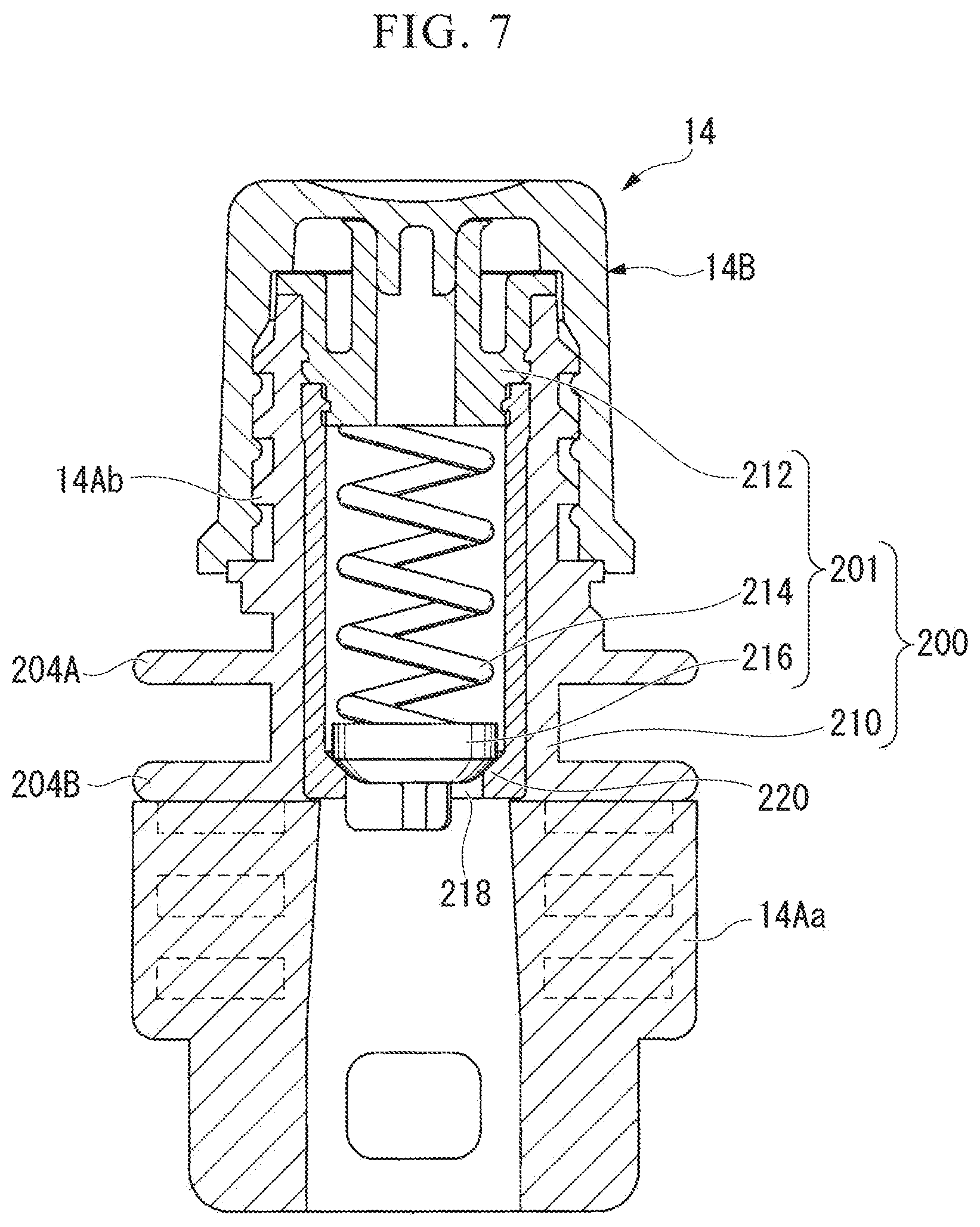
[0075] An example of a specific structure of the spout 14 having a check valve function of the second embodiment will be described below with reference to FIGS. 7 to 9. Further, FIG. 7 shows an overall configuration of the spout 14 having a check valve function and FIGS. 8 and 9 show a check valve 200 incorporated in the spout 14.
[0076] As shown in FIG. 7, the spout 14 having the check valve function includes the spout member 14A which includes the bonded portion 14Aa located at the inside of the trunk member 10A at the upper end of the trunk section 10 of the self-standing packing bag with the spout 1 and sandwiched between the inner surfaces of the trunk member 10A and the discharge portion 14Ab bonded to the upper end of the bonded portion 14Aa and holding the check valve 200, the check valve 200 which is incorporated in the spout member 14A, and the cap 14B which is threaded into the upper end of the spout member 14A.
[0077] Flanges 204A and 204B are formed to protrude in two steps on the lower outer periphery of the discharge portion 14Ab. The bonded portion 14Aa is located at the inside of the trunk member 10A and is bonded to the trunk member 10A while being sandwiched between the inner surfaces of the trunk member 10A.
[0078] For example, as shown in FIGS. 8 and 9, the check valve 200 includes a hollow cylindrical member 210 and a valve member 211. The valve member 211 includes a spout member 212, an urging member 214 that has, for example, a coil spring shape and of which a base end portion 214a is supported by the inner end portion of the spout member 212, and a valve body 216 which is provided at the lower end of the urging member 214, the spout member 212 is fixed to one end (the upper end in FIG. 8) of the cylindrical member 210 in the axial direction, and the valve member 211 is fixed to the cylindrical member 210 so that the urging member 214 and the valve body 216 are built in the cylindrical member 210. An inlet 218 of the lower end of the cylindrical member 210 is provided with a valve seat portion 220. The urging member 214 is configured to close the inlet 218 by pressing the valve body 216 against the valve seat portion 220. The inside of the spout member 212 is provided with a pouring passage 212A of which a lower end communicates with the cylindrical member 210 and an upper end is provided with a pouring outlet 212Aa.
[0079] The urging member 214 is used to urge the valve body 216 in a direction in which the valve body 216 is pressed against the valve seat portion 220 of the inlet 218 at a predetermined pressure and an elastic urging force is set such that the inlet 218 is closed in a normal state (a state in which no pressure is applied to the self-standing packaging bag with the spout 1 from outside by fingers to pour out contents) and the urging member is elastically compressed by the pressure from the inside of the self-standing packing bag with the spout 1 so as to form a gap between the valve body 216 and the valve seat portion 220 and open the inlet 218 in a state in which a certain degree of a pressure is applied to the self-standing packing bag with the spout 1 from the outside by fingers.
[0080] In the spout 14 with the check valve 200, the valve body 216 is pressed against the valve seat portion 220 so that the inlet 218 is closed in a normal state, that is, a state in which no pressure is applied to the self-standing packing bag with the spout 1 from the outside by fingers so as to pour out the contents. Then, in this state, air is prevented from entering the spout 14 from the outside to the inside of the self-standing packaging bag with the spout 1 via the spout 14 regardless of the presence or absence of the cap 14B. On the other hand, when the cap 14B is separated and a certain degree or more of a pressure is applied to the self-standing packing bag with the spout 1 from the outside by fingers, a pressure is applied from the self-standing packing bag with the spout 1 to the valve body 216. Then, when the pressure becomes larger than the urging force of the urging member 214, the urging member 214 is elastically compressed and a gap is formed between the valve body 216 and the valve seat portion 220 so that the inlet 218 is opened. Thus, the contents in the self-standing packing bag with the spout 1 can pass from the inlet 218 through the passage 224 in the cylindrical member 210 and the pouring passage 212A of the spout member 212 and can be poured from the pouring outlet 212Aa to the outside of the self-standing packing bag with the spout 1.
[0081] Further, the structure of the check valve is not limited to the above-described check valve. In short, the check valve may have a check function.
[0082] In the self-standing packing bag with the spout of the present invention, since the extending direction of the fold line of the bottom section intersects the closing direction of the upper end of the trunk section, the three-dimensional shape is maintained even when the contents are not stored. When transporting or storing such a self-standing packing bag with the spout in a state in which the contents are not stored, it is preferable to fold the bag into a flat shape so as to save a space and maintain a stable posture.
[0083] As a folding method, for example, there is a method gradually shown in FIGS. 10A, 10B, 10C, 11A, 11B, and 11C. This method will be described next. FIG. 11A shows a step to be performed next to FIG. 10C.
[0084] FIG. 10A schematically shows the self-standing packing bag with the spout 1 of the first embodiment before the bag not filled with the contents is folded. From this state, as shown in FIG. 10B, a lower portion (a portion including the bottom section 12) 300C of the trunk section 10 of the self-standing packing bag with the spout 1 is made flat along the extending direction of the fold line 16 of the bottom section 12. That is, the bottom section front surface 121 and the bottom section rear surface 122 which are divided by the fold line 16 of the bottom section 12 overlap each other so that the lower portion 300C of the self-standing packing bag with the spout 1 is made flat. Next, the upper portion 300A of the trunk section 10 or the closing portion 10b of the upper end is made flat in the extending direction. Here, in the lines descending from both side end portions of the closing portion 10b of the trunk section 10, the lower end points where the upper portion of the trunk section 10 is flat are referred to as upper portion lower end side end portions 305 and 306. At this time, an intermediate portion 300B between the flat upper portion 300A and the fiat lower portion 300C of the trunk section 10 spreads three-dimensionally. Here, a three-dimensional intermediate portion below the upper portion lower end side end portion 305 in the trunk section front surface 101 is referred to as an intermediate portion front surface portion 301 and a three-dimensional intermediate portion below the upper portion lower end side end portion 306 in the trunk section rear surface 102 is referred to as an intermediate portion rear surface portion 302.
[0085] Next, as shown in FIG. 10C, in the lower portion 300C of the trunk section 10, a line following the fold line 16 of the bottom section 12 and connecting both side ends of the trunk section 10 is used as a first auxiliary fold line 303A for folding, the trunk section 10 and the bottom section 12 located below the first auxiliary fold line 303A are set as the lower part 304, and the lower part 304 is folded forward by 90.degree. in an overlapping flat state. Further, in some cases, the lower part 304 may be folded forward by 180.degree. in an overlapping flat state, but here, in order to make the figure of the subsequent procedure easy to understand, the subsequent procedure will be described by assuming that the lower part 304 is folded forward by 90.degree. in an overlapping flat state as described above.
[0086] Further, as shown in FIGS. 11A to 11B, the intermediate portion front surface portion 301 is mountain-folded along a second auxiliary fold line 303B and a third auxiliary fold line 303C which are hypotenuses of a triangle so that the intermediate portion front surface portion 301 forms a triangle in which the upper portion lower end side end portion 305 is an apex and the first auxiliary fold line 303A is a base. Similarly, a fourth auxiliary fold line 303D and a fifth auxiliary fold line 303E which are hypotenuses of a triangle are mountain-folded so that the intermediate portion rear surface portion 302 forms a triangle in which the upper portion lower end side end portion 306 is an apex and the first auxiliary fold line 303A is a base.
[0087] In a state shown in FIG. 11B, the self-standing packing bag with the spout 1 still has a three-dimensional shape, but the intermediate portion 300B of the trunk section 10 is also flat on the same plane as the lower portion 300C. Here, as shown in FIGS. 11B to 11C, the upper portion 300A of the trunk section 10 is folded along a fifth auxiliary fold line 307 which is a line connecting the upper portion lower end side end portions 305 and 306 corresponding to the apexes of the above-described triangle and is inclined on the same plane as the intermediate portion 300B and the lower portion 300C. Accordingly, as shown in FIG. 11C, the entire self-standing packing bag with the spout 1 is made flat.
[0088] Further, the triangle in which the upper portion lower end side end portion 305 is an apex and the first auxiliary fold line 303A is a base and the triangle in which the upper portion lower end side end portion 306 is an apex and the first auxiliary fold line 303A is a base are isosceles triangles when the extending direction of the fold line 16 of the bottom section 12 intersects the extending direction of the closing portion 10b closing the upper end of the trunk section 10 at 90.degree..
[0089] Further, in the method of folding the self-standing packing bag with the spout, the intermediate portion of the trunk section may be folded before the upper portion of the trunk section is made flat. Furthermore, in the description above, a folding method from the lower portion of the trunk section has been described, but a folding method from the upper portion of the trunk section may be used.
[0090] Further, instead of folding the lower part 304 shown in FIG. 10C by 90.degree. in an overlapping flat state, the lower part 304 may be folded backward by 90.degree. in an overlapping flat state, but is preferably folded forward as shown in FIG. 10C. This is because the trunk section bonded portion 10a having a more complicated structure than the trunk section front surface 101 is folded by 90.degree. and 180.degree. (when the lower part faces reversely in FIG. 11B) when the lower part is folded backward. In this case, the folding is difficult.
[0091] Further, in the manufactured self-standing packing bag with the spout, since there is a case in which the lower portion or the upper portion of the bottom section and the trunk section may be flat, a state shown in FIG. 10A may be omitted in that case.
[0092] Although the preferred embodiments of the present invention have been described, the above-described embodiments are merely examples within the scope of the spirit of the present invention and the components can be added, omitted, substituted, and modified in other forms without departing from the spirit of the present invention. That is, the present invention is not limited to the description above, is limited only by the accompanied claims, and can be, of course, appropriately modified within its scope.
INDUSTRIAL APPLICABILITY
[0093] According to the present invention, since it is possible to provide the self-standing packing bag with the spout including: the trunk section which is formed in a cylindrical shape and of which the upper end is closed; the bottom section which is attached to the lower portion of the trunk section; and the spout which is attached to the upper end of the trunk section, it is possible to reliably secure self-standing ability and to reduce the possibility of the bag breakage at the upper end of the bonded portion with a structure in which contents hardly ride on a bonded portion between the trunk section and the bottom section.
REFERENCE SIGNS LIST
[0094] 1: Self-standing packing bag with spout
[0095] 10: Trunk section
[0096] 10A: Trunk member
[0097] 10b: Closing portion
[0098] 12: Bottom section
[0099] 12A: Bottom member
[0100] 123, 124: Side end portion of bottom member
[0101] 14: Spout
[0102] 16: Fold line
* * * * *
D00000
D00001
D00002
D00003
D00004
D00005
D00006
D00007
D00008
D00009
D00010
D00011
XML
uspto.report is an independent third-party trademark research tool that is not affiliated, endorsed, or sponsored by the United States Patent and Trademark Office (USPTO) or any other governmental organization. The information provided by uspto.report is based on publicly available data at the time of writing and is intended for informational purposes only.
While we strive to provide accurate and up-to-date information, we do not guarantee the accuracy, completeness, reliability, or suitability of the information displayed on this site. The use of this site is at your own risk. Any reliance you place on such information is therefore strictly at your own risk.
All official trademark data, including owner information, should be verified by visiting the official USPTO website at www.uspto.gov. This site is not intended to replace professional legal advice and should not be used as a substitute for consulting with a legal professional who is knowledgeable about trademark law.