Container With A Cover Snapped To A Base
Wang; Jacky ; et al.
U.S. patent application number 16/909781 was filed with the patent office on 2021-02-25 for container with a cover snapped to a base. The applicant listed for this patent is Relocks Co., Ltd. Invention is credited to Jacky Wang, Ssu-Wei Wu.
| Application Number | 20210053728 16/909781 |
| Document ID | / |
| Family ID | 1000004954742 |
| Filed Date | 2021-02-25 |


| United States Patent Application | 20210053728 |
| Kind Code | A1 |
| Wang; Jacky ; et al. | February 25, 2021 |
CONTAINER WITH A COVER SNAPPED TO A BASE
Abstract
A container includes a base and a cover which is snapped to the base. The cover includes at least one recess defined in lateral face thereof. The base includes a peripheral wall which has a reception area. The reception area includes a stop wall that extends from the peripheral wall, and a snapping member extends from the reception area and includes a protrusion. The at least one recess includes a wide top opening and a narrow bottom. The protrusion is shaped to be engaged with the at least one recess to connect the cover to the base. The base includes stop wall which reinforces the base strength to avoid from being deformed.
| Inventors: | Wang; Jacky; (Taoyuan City, TW) ; Wu; Ssu-Wei; (New Taipei City, TW) | ||||||||||
| Applicant: |
|
||||||||||
|---|---|---|---|---|---|---|---|---|---|---|---|
| Family ID: | 1000004954742 | ||||||||||
| Appl. No.: | 16/909781 | ||||||||||
| Filed: | June 23, 2020 |
| Current U.S. Class: | 1/1 |
| Current CPC Class: | B65D 51/242 20130101; B65D 2543/00694 20130101; B65D 2543/00824 20130101; B65D 43/0206 20130101; B65D 2543/00092 20130101; B65D 2543/00212 20130101 |
| International Class: | B65D 43/02 20060101 B65D043/02; B65D 51/24 20060101 B65D051/24 |
Foreign Application Data
| Date | Code | Application Number |
|---|---|---|
| Aug 23, 2019 | TW | 108211274 |
Claims
1. A container comprising: a cover having a cover top, a lateral face extending from a periphery of the cover top, the cover having a protruding portion formed by the lateral face together with the cover top, the lateral face having at least one recess which includes a wide top opening and a narrow bottom, and a base including a top opening which is defined by a peripheral wall, the cover being mounted to the top opening of the base to form a space between the base and the cover, the peripheral wall of the base having a recessed area which forms a reception area located corresponding to the at least one recess of the cover, the reception area having a stop wall that extends from the peripheral wall, a snapping member extending from the reception area and having a protrusion, the protrusion being shaped to be engaged with the at least one recess to connect the cover to the base, the at least one recess located between the stop wall and the snapping member when the protrusion of the base is engaged with the at least one recess of the cover.
2. The container as claimed in claim 1, wherein a lip extends from the reception area along the top opening of the base, the lateral face of the cover includes a skirt extending therefrom.
3. The container as claimed in claim 2, wherein the skirt contacts the lip when the cover is mounted to the base.
4. The container as claimed in claim 2, wherein a bending portion is formed between the lip and the snapping member.
5. The container as claimed in claim 1, wherein an extension portion member extends from the protrusion of the base.
6. The container as claimed in claim 1, wherein the protrusion includes a recessed portion formed in a rear side thereof.
7. The container as claimed in claim 1, wherein the at least one recess is located between two reinforcement portions, a contact face is formed between the two reinforcement portions, the at least one recess is defined between the contact face and the two reinforcement portions.
8. The container as claimed in claim 1, wherein the base and the cover are shaped to include a curve periphery or multiple sides.
9. The container as claimed in claim 1, wherein there are multiple recesses, the snapping member includes multiple protrusions, a number of the protrusions is the same as a number of the recesses.
10. The container as claimed in claim 1, wherein there are multiple recesses and multiple snapping members, a number of the protrusions of the snapping members is the same as a number of the recesses.
11. The container as claimed in claim 1, wherein there are multiple recesses, a number of the snapping members is the same as a number of the recesses, each snapping member includes a protrusion.
12. The container as claimed in claim 1 further comprising a handle, a hole is formed through each of two ends of the handle, the protrusions are engaged with the two holes of the handle, a grip portion is formed between the two ends of the handle.
Description
BACKGROUND OF THE INVENTION
1. Fields of the Invention
[0001] The present invention relates to a container, and more particularly, to a container with a cover which is snapped to a base.
2. Descriptions of Related Art
[0002] The conventional containers are made by plastic or paper-related material, wherein the containers with a cover that is able to seal the base to keep food fresh are welcomed in the marked. Especially for those container made by plastic are able to prevent liquid from splitting out and are used in different ways.
[0003] An important feature of this type of plastic-made containers is the stability and reliability of the cover that is connected to the base. For the conventional plastic-made containers generally includes hooks formed along sides of the cover, and the base includes lips which are hooked by the hooks. However, this snapping engagement the snapping engagement may be too lose to seal the base, or may be too firm to release. For the first situation, the hooks simply engaged with the edge of the lips so that the hooks cannot firmly engaged with the lips. The engagement can be loosened by impact or squeeze. The hooks may also be disengaged from the lips due to the food in the container is heavy or the way that the users to gran the cover improperly. For the second situation, there are different forms of the hooks and lips, such as hooks engaged with recesses in ridges. If the hooks have an exaggerated curvature or the width of the lips is not properly set, or the hooks are too big when comparted with the recesses of the ridges. The friction between the hooks and lips will be significant so that the cover is difficult to be opened or even deforms the cover or the base.
[0004] Another snapping device for containers includes a male part and a female part, wherein the male and female parts are engaged with each other by way of surface-surface engagement. If there are tolerances between the male and female parts, the resistance is significant so that the cover is difficult to close and to open relative to the base. Besides, the male parts have to be pressed hard so as to be connected with the female parts, the male parts or the female parts may be deformed if there is no reinforcement structure to support the pressing action. Because the existed molding technology, it is difficult to form the male parts on lateral sides of the base. The existed problems need to be further improved.
[0005] The present invention intends to provide a container composed of a cover and a base to eliminate shortcomings mentioned above.
SUMMARY OF THE INVENTION
[0006] The primary object of the present invention is to provide a container that includes a base and a cover which is snapped to the base. The cover includes at least one recess defined in lateral face thereof. The base includes a snapping member so that the snapping member includes protrusion which is engaged with the at least one recess to connect the cover to the base. The base includes a reception area which reinforces the strength of the at least one recess to shorten the snapping member and to reduce the cover height and the material needed so as to save material and cost. The container includes a stable and simple structure. The container is not deformed even being squeezed to reduce possibility of disengagement and separation.
[0007] In order to achieve the above mentioned objective, the present invention relates to a container that comprises a cover and a base. The cover includes a cover top, and a lateral face extends from the periphery of the cover top. A protruding portion is formed by the lateral face together with the cover top. The lateral face has at least one recess which includes a wide top opening and a narrow bottom. The base includes a top opening which is defined by the peripheral wall. The cover is mounted to the top opening of the base to form a space between the base and the cover. The peripheral wall of the base has a recessed area which forms a reception area located corresponding to the at least one recess of the cover. The reception area has a stop wall that extends from the peripheral wall. A snapping member extends from the reception area and has a protrusion. The protrusion is shaped to be engaged with the at least one recess to connect the cover to the base.
[0008] Preferably, a lip extends from the reception area along the top opening of the base. The lateral face of the cover includes a skirt extending therefrom. The skirt contacts the lip when the cover is mounted to the base.
[0009] Preferably, a reception area is formed at the connection between the lip and the snapping member. The reception area includes a stop wall extending upward. When the cover is connected to the base, the at least one recess is located between the stop wall and the snapping member.
[0010] Preferably, an extension portion member extends from the protrusion of the base. The protrusion includes a recessed portion formed in the rear side thereof. A bending portion is formed between the lip and the snapping member.
[0011] Preferably, the at least one recess is located between two reinforcement portions. A contact face is formed between the two reinforcement portions. The at least one recess is defined between the contact face and the two reinforcement portions.
[0012] Preferably, the base and the cover are shaped to include a curve periphery or multiple sides.
[0013] Preferably, there are multiple recesses, and the snapping member includes multiple protrusions. The number of the protrusions is the same as the number of the recesses.
[0014] Preferably, there are multiple recesses and multiple snapping members. The number of the protrusions of the snapping members is the same as the number of the recesses.
[0015] Preferably, there are multiple recesses. The number of the snapping members is the same as the number of the recesses, and each snapping member includes a protrusion.
[0016] Preferably, the container comprises a handle, and a hole is formed through each of two ends of the handle. The protrusions are engaged with the two holes of the handle. A grip portion is formed between the two ends of the handle.
[0017] In one embodiment, the recesses and the protrusions can be switches. The protrusions are located on the base, and the recesses are located in the cover. Alternatively, the protrusions are located on the cover, and the recesses are located in the base.
[0018] The container may have the engagement parts on the corresponding lateral sides of the base and the cover. Therefore, the strength of the cover and the base is reinforced so that the cover and the base are not deformed due to squeezing to separate the protrusions from the recesses. The base has stop walls so that the snapping member can be shortened to reduce the cover height. The stop wall reinforces the strength of the recesses such that the protrusions are not disengaged from the recesses due to squeezing, and the container is likely deformed. Besides, the thickness of the cover can be reduced to achieve the market's demand of thin cover and low cover.
[0019] The present invention will become more obvious from the following description when taken in connection with the accompanying drawings which show, for purposes of illustration only, a preferred embodiment in accordance with the present invention.
BRIEF DESCRIPTION OF THE DRAWINGS
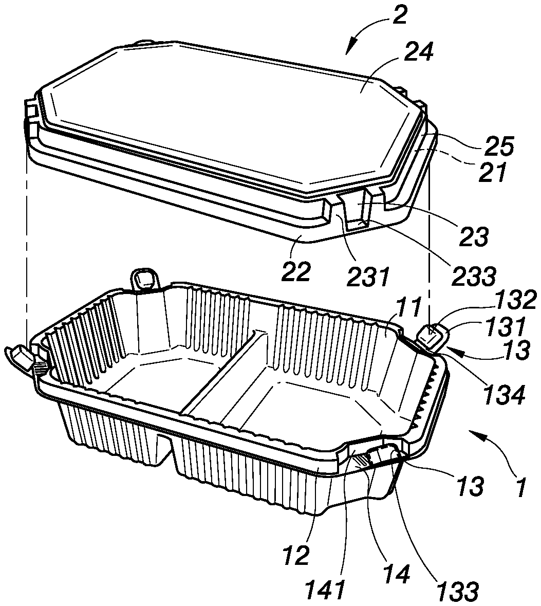
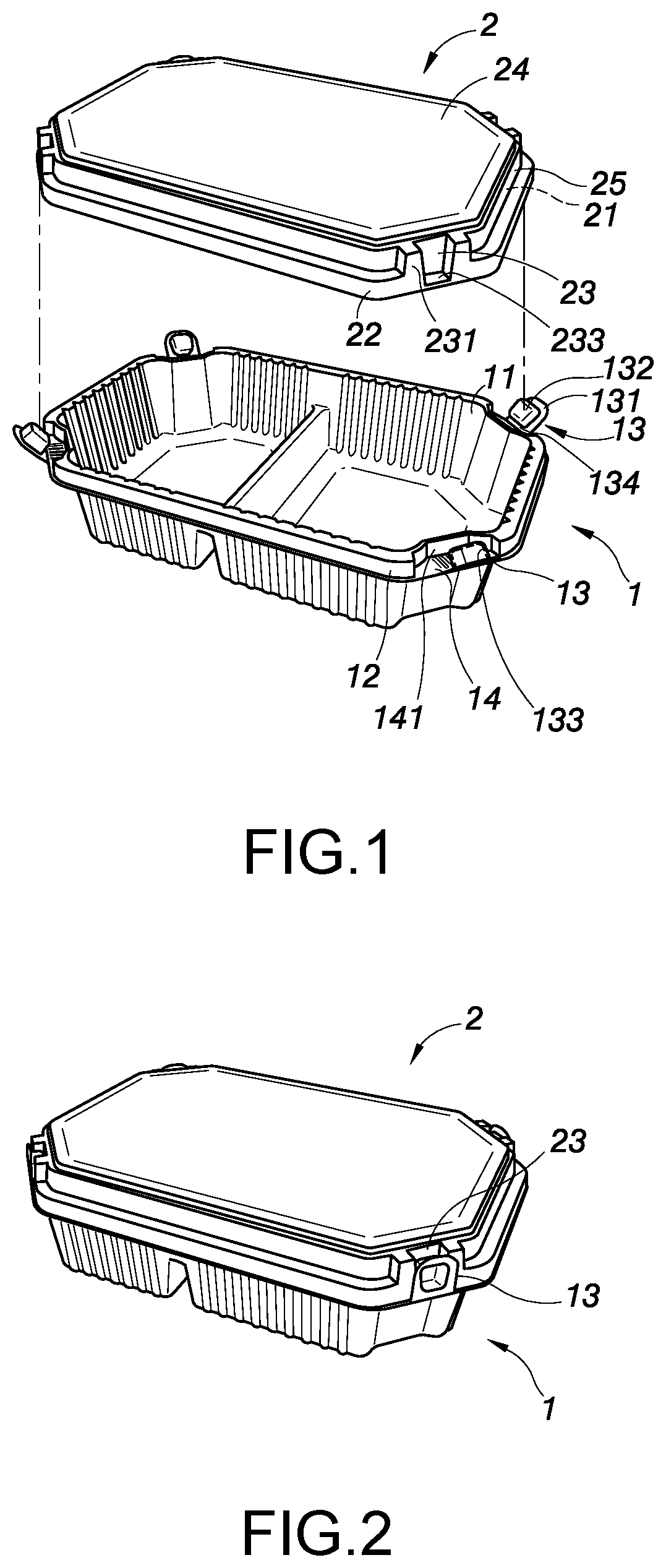
[0020] FIG. 1 is an exploded view of the container of the present invention;
[0021] FIG. 2 is a perspective view to show the container of the present invention;
[0022] FIG. 3 is a side cross sectional view to show the snapping member and the protrusion on the base wherein the protrusion is engaged with the recess of the cover;
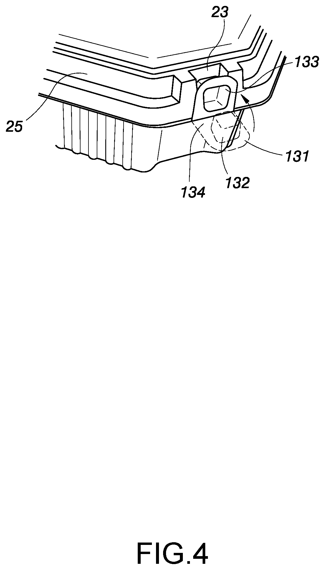
[0023] FIG. 4 shows the action of the protrusion engaged with the recess of the cover;
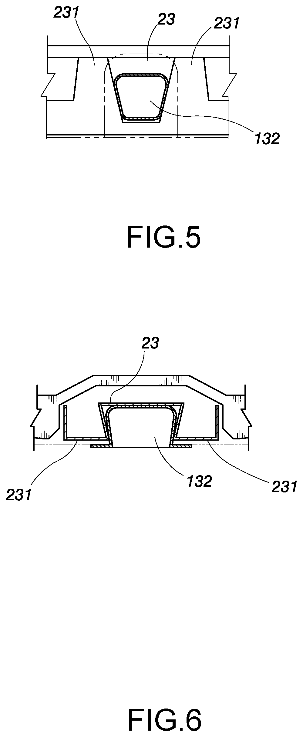
[0024] FIG. 5 is a partial cross sectional side view to shown that the protrusion is engaged with the recess;
[0025] FIG. 6 is a partial cross sectional top view to shown that the protrusion is engaged with the recess;
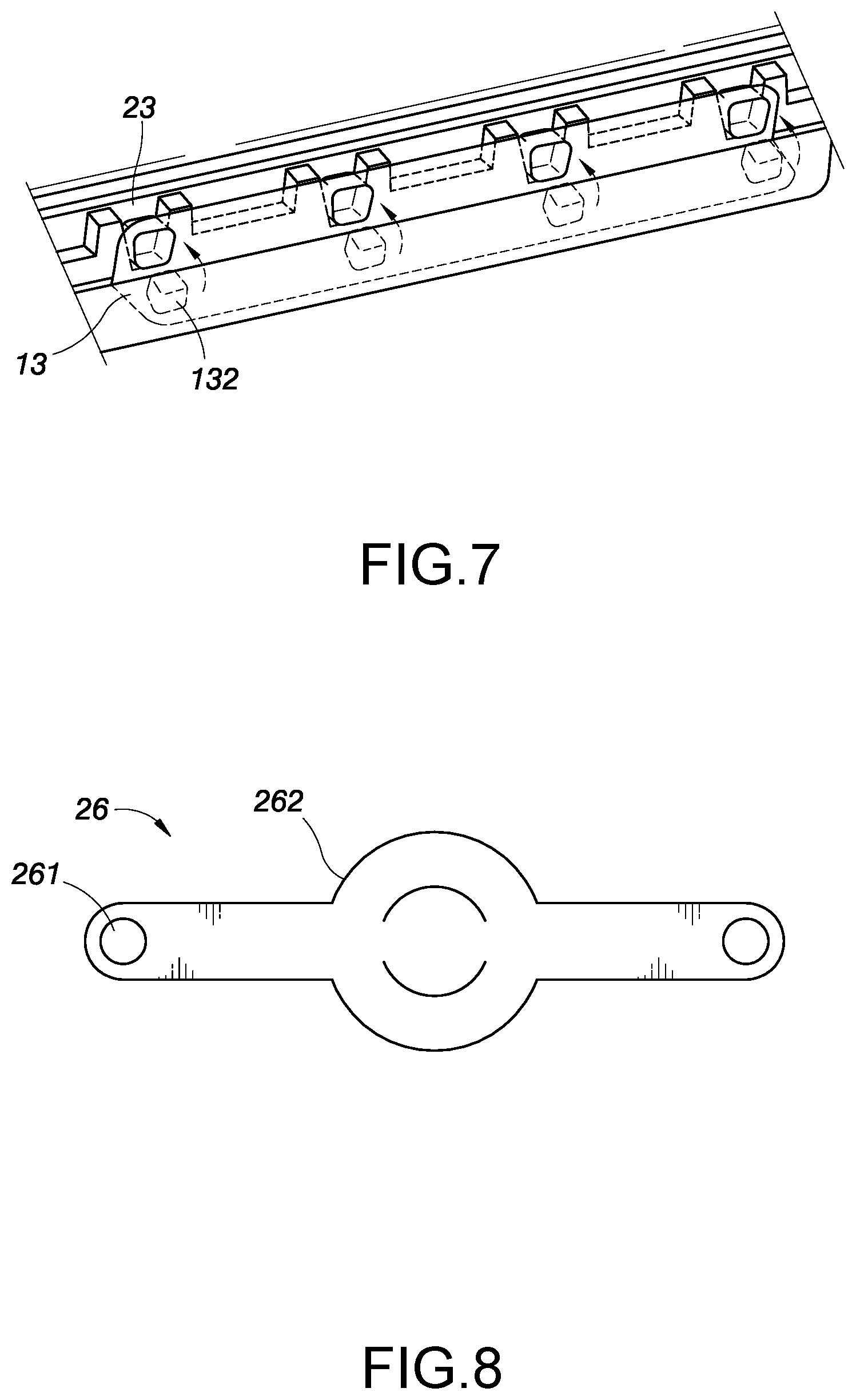
[0026] FIG. 7 shows that the snapping member with multiple protrusions which are engaged with multiple recesses;
[0027] FIG. 8 shows the handle for the container of the present invention, and
[0028] FIG. 9 shows the container of the present invention is equipped with the handle as shown in FIG. 8.
DETAILED DESCRIPTION OF THE PREFERRED EMBODIMENT
[0029] Referring to FIGS. 1 and 2, the container of the present invention can be made by paper or plastic, and comprises a base 1 and a cover 2.
[0030] The base 1 includes a top opening which is defined by a peripheral wall 11. A lip 12 extends from the periphery of the top opening and is bent downward. A reception area 14 is formed in a recessed area of the lip 12 and the reception area 14 has a stop wall 141 that extends from the peripheral wall 11 so as to reinforce the strength of the reception area 14. At least one snapping member 13 extends from the reception area 14 and includes a protrusion 132. In this embodiment, there are multiple snapping members 13. The protrusion 132 includes a recessed portion 133 formed to its rear side. The connection between the snapping member 13 and the lip 12 is a bending portion 134.
[0031] The cover 2 includes a cover top 24, and a lateral face 25 extends from the periphery of the cover top 24. A protruding portion 21 is formed by the lateral face 25 together with the cover top 24. The cover 2 is mounted to the top opening of the base 1 to form a space between the peripheral wall 11 of the base 1 and the protruding portion 21 of the cover 2. The lateral face 25 of the cover 2 includes a skirt 22 extending therefrom. The skirt 22 contacts the lip 12 when the cover 2 is mounted to the base 1. The lateral face 25 includes at least one recess 23 which includes a wide top opening and a narrow bottom. In this embodiment, there are multiple recesses 23. Each recess 23 is located between two reinforcement portions 231. A contact face 233 (FIG. 3) is formed between the two reinforcement portions 231. Each recess 23 is defined between the contact face 233 and the two reinforcement portions 231. The reinforcement portions 231 reinforce the strength of the cover 2 to prevent the cover 2 from being deformed. The covers 2 are able to be piled and are not deformed. The contact face 233 provides a support when the protrusion 132 is engaged with the recess 23. The contact face 233 also prevents the protrusion 132 from slipping away from the recess 23.
[0032] The recessed area that the reception area 14 forms allows the recess 23 of the cover 2 to be lowered and positioned in the reception area 14. Therefore, the length of the snapping member 13 can be shortened, and this also saves material needed. The height of the cover 2 can also be reduced to meet the requirement of a thin cover which needs less material. The stop wall 141 provide a support to the recess 23 when the protrusion 132 is engaged with the recess 23, the recess 23 moved inward. In other words, because the stop wall 141 stops the recess 23 from further moving inward so that the recess 23 is supported by the stop wall 141 and the protrusion 132 is easily engaged with the recess 23.
[0033] FIGS. 3 and 4 show the first embodiment of the container of the present invention.
[0034] The snapping members 13 of the base 1 are bent by the bending portion 134 which is connected to the reception area 14. As shown in FIG. 3, the protruded area 135 of the protrusion 132 is integrally formed with the protrusion 132 and can be made by plastic or paper, so that the protruded area 135 is strong enough and is not deformed when the protrusion 132 is slightly force-fitted in the recess 23.
[0035] When the cover 2 is mounted to the base 1, the user can press the recessed portion 133 of the snapping member 13 to bend the snapping member 133 by the bending portion 134 so as to engage the protrusion 132 with the recess 23. When removing the cover 2 from the base 1, the protrusion 132 is disengaged from the recess 23 by pulling the extension portion member 131.
[0036] It is noted that when opening the cover 2 relative to the base 1 to access the food in the container, the user simply separates the protrusions 132 of one snapping member 13 from the recesses 23, the cover 2 can be pivoted 90 or 180 degrees from the base 1 by the bending portions 134. It is not necessary to separate all the protrusions 132 of all of the snapping members 13 from the recesses 23.
[0037] Besides, because the skirt 22 of the cover 2 is mounted to and contacts the edge of the lip 12 of the base 1, so that when the protrusions 132 are engaged with the recesses 23, the cover 2 is securely mounted to the base 1. Even the container is put upside down, the food does not leak out.
[0038] FIGS. 5 and 6 show that the protrusions 132 are engaged with the recesses 23.
[0039] The recess 23 provides a space for the protrusion 132 to be engaged with, and the space is formed between the reinforcement portions 231 and the contact face 233. The width of the protrusion 132 is slightly larger than the width of the recess 23 between the two reinforcement portions 231. Therefore, the protrusion 132 can be securely engaged with the recess 23 and contacts the contact face 233. Because the recess 23 has a wide top opening and a narrow bottom, the protrusion 132 is even more securely engaged with the recess 23 when the container is pressed or squeezed. Each recess 23 includes a wide top opening, and the sidewalls of the reinforcement portions 231 are inclined walls with a positive draft angle, both of which make the molding action be easily. In other words, the recess 23 is not deformed to ensure the engagement between the protrusion 132 and the recess 23. The contact face 233 prevents the protrusion 132 from dropping from the recess 23 when the container is shaken or put upside down. The two reinforcement portions 231 are two protruded portions which include multiple faces to form a strong structure to support the pressing action of the protrusion 132 to the recess 23.
[0040] In the embodiment mentioned above, the number of the snapping members 13 is the same as the number of the recesses 23, and each snapping member 13 includes a protrusion 132. Alternatively, the number of the recesses 23 can be single or multiple. When the number of the recess 23 is one, then there is a snapping member 13. When the number of the recesses 23 are multiple, then there is one or more than one snapping members 13. Each snapping member 13 includes one or more than one protrusions 132. The number of the protrusions 132 is the same as the number of the recesses 23. In other words, the number of the protrusions 132 of all of the snapping members 13 is the same as the number of the recesses 23.
[0041] FIG. 7 shows the second embodiment of the container of the present invention, wherein each snapping members 13 includes multiple protrusions 132.
[0042] The differences between the second embodiment and the first embodiment are that the base 1 includes two elongate snapping members 13 respectively formed on two sides thereof, and each snapping member 13 includes multiple protrusions 132. The number of the protrusions 132 of the snapping members 13 is the same as the number of the recesses 23, so that the protrusions 132 are engaged with the recesses 23 correspondingly.
[0043] FIG. 8 shows the handle 26 of the third embodiment of the container of the present invention, and FIG. 9 shows the container of the present invention is equipped with the handle 26.
[0044] The handle 26 includes a hole 261 formed through each of two ends thereof. A grip portion 262 is formed between the two ends of the handle 26. The protrusions 132 of two snapping members 13 are engaged with the two holes 261 of the handle 26. The two protrusions 132 connected with the handle 26 are engaged with the recesses 23 corresponding thereto. The users may hold the grip portion 262 to carry the container.
[0045] The container can be a rectangular or round container to include a rectangular or round base 1 and cover 2. Of course, the base 1 and the cover 2 can be shaped to include a curve periphery or multiple sides.
[0046] The recesses 23, the snapping members 13 and the protrusions 132 can be modified to include any size, number and arrangement. For examples, the container may include multiple pairs snapping members 13 and recesses 23 to obtain better strength to the cover 2, so that the cover 2 is securely connected to the base 1. The positions of the recesses 23 and the protrusions 132 can be changed. The protrusions 132 can be located on the base 1, and the recesses 23 can be located in the cover 2. Alternatively, the protrusions 132 can be located on the cover 2, and the recesses 23 are located in the base 1.
[0047] While we have shown and described the embodiment in accordance with the present invention, it should be clear to those skilled in the art that further embodiments may be made without departing from the scope of the present invention.
* * * * *
D00000
D00001
D00002
D00003
D00004
D00005
D00006
XML
uspto.report is an independent third-party trademark research tool that is not affiliated, endorsed, or sponsored by the United States Patent and Trademark Office (USPTO) or any other governmental organization. The information provided by uspto.report is based on publicly available data at the time of writing and is intended for informational purposes only.
While we strive to provide accurate and up-to-date information, we do not guarantee the accuracy, completeness, reliability, or suitability of the information displayed on this site. The use of this site is at your own risk. Any reliance you place on such information is therefore strictly at your own risk.
All official trademark data, including owner information, should be verified by visiting the official USPTO website at www.uspto.gov. This site is not intended to replace professional legal advice and should not be used as a substitute for consulting with a legal professional who is knowledgeable about trademark law.