Rack System For Vehicles
Badillo; Paul
U.S. patent application number 17/093276 was filed with the patent office on 2021-02-25 for rack system for vehicles. This patent application is currently assigned to INTELLIGENT DESIGNS 2000 CORP.. The applicant listed for this patent is INTELLIGENT DESIGNS 2000 CORP.. Invention is credited to Paul Badillo.
| Application Number | 20210053503 17/093276 |
| Document ID | / |
| Family ID | 1000005207202 |
| Filed Date | 2021-02-25 |


View All Diagrams
| United States Patent Application | 20210053503 |
| Kind Code | A1 |
| Badillo; Paul | February 25, 2021 |
RACK SYSTEM FOR VEHICLES
Abstract
A rotatable rack is provided. The rotatable rack is rotatably interconnected to a vehicle proximal to the vehicle's windshield such that the rotatable rack is capable of moving from a first position of use adjacent to the windshield to a second position away from the windshield where the rotatable rack is provided proximal to a hood of the vehicle.
| Inventors: | Badillo; Paul; (Littleton, CO) | ||||||||||
| Applicant: |
|
||||||||||
|---|---|---|---|---|---|---|---|---|---|---|---|
| Assignee: | INTELLIGENT DESIGNS 2000
CORP. AURORA CO |
||||||||||
| Family ID: | 1000005207202 | ||||||||||
| Appl. No.: | 17/093276 | ||||||||||
| Filed: | November 9, 2020 |
Related U.S. Patent Documents
| Application Number | Filing Date | Patent Number | ||
|---|---|---|---|---|
| 16355179 | Mar 15, 2019 | 10829055 | ||
| 17093276 | ||||
| 62644184 | Mar 16, 2018 | |||
| Current U.S. Class: | 1/1 |
| Current CPC Class: | B60R 9/06 20130101 |
| International Class: | B60R 9/06 20060101 B60R009/06 |
Claims
1-20. (canceled)
21. A brace to interconnect a rack to a vehicle, comprising: a first plate that is substantially planar and includes: a front edge, a rear edge, and a first aperture positioned therebetween; a second plate that is substantially planar and includes: an upper edge, a lower edge, and a second aperture positioned therebetween, wherein the second plate is oriented approximately perpendicular to the first plate; and a medial portion positioned between the first plate and the second plate and includes: a first medial section extending from the rear edge of the first plate; and a second medial section extending from the upper edge of the second plate.
22. The brace of claim 21, wherein the first medial section is oriented transverse to the second medial section.
23. The brace of claim 21, wherein the second aperture is elongated to define a slot.
24. The brace of claim 21, wherein: the first medial section is connected to the rear edge of the first plate by a first bend such that the first medial section extends downwardly from the first plate; the second medial section connected is connected to the first medial section by a second bend; and the second medial section is connected to the upper edge of the second plate by a third bend such that the second plate extends downwardly from the second medial section.
25. The brace of claim 24, wherein the second medial section includes an arcuate edge that extends between the first medial section and the upper edge of the second plate.
26. The brace of claim 24, wherein the first plate is approximately perpendicular to the first medial section.
27. The brace of claim 26, wherein the first medial section is approximately perpendicular to the second medial section.
28. The brace of claim 27, wherein the second medial section is approximately perpendicular to the second plate.
29. The brace of claim 24, wherein the first medial section is substantially planar and the second medial section is substantially planar.
30. The brace of claim 21, wherein the brace is configured such that when the rack is connected to the vehicle: a first bolt is extendable through the first aperture, wherein the first plate is positioned inwardly relative to an interior surface of a cowling of the vehicle; and a second bolt is extendable through the second aperture, wherein the second plate is positioned proximate to a door hinge of the vehicle.
31. A brace to interconnect a rack to a vehicle, comprising: a first portion with a first aperture to receive a first bolt, the first portion being generally planar; a first medial section connected to the first portion by a first bend, the first medial section being generally planar and extending downwardly from the first bend; a second medial section connected to the first medial section by a second bend, the second medial section being generally planar and extending laterally from the second bend; and a second portion connected to the second medial section by a third bend, the second portion: being generally planar; extending downwardly from the third bend; and including a second aperture to receive a second bolt.
32. The brace of claim 31, wherein: the first portion is approximately perpendicular to the first medial section; the first medial section is approximately perpendicular to the second medial section; and the second medial section is approximately perpendicular to the second portion.
33. A rack adapted for use with a vehicle, comprising: a first brace that is selectively securable to a first door hinge of the vehicle and includes a first brace aperture adapted to be aligned with a first cowling aperture on a first side of the vehicle; a second brace that is selectively securable to a second door hinge of the vehicle and includes a second brace aperture adapted to be aligned with a second cowling aperture on a second side of the vehicle; and a rack member adapted to be associated with the vehicle and positioned adjacent to a windshield of the vehicle, the rack member including: a first support member with a first support aperture configured to align with the first brace aperture and the first cowling aperture to receive a first cowling fastener to interconnect the first support member and the first brace to the first side of the vehicle; and a second support member with a second support aperture configured to align with the second brace aperture and the second cowling aperture to receive a second cowling fastener to interconnect the second support member and the second brace to the second side of the vehicle.
34. The rack of claim 33, further comprising: a first bracket member that is selectively securable to the vehicle such that a first through-hole of the first bracket member extends from a first gap between exterior panels of the vehicle, wherein the first bracket member comprises a first clamp plate configured to engage a first fastener under the exterior panels of the vehicle, and wherein a first flange of the rack member is selectively securable to the first through-hole; and a second bracket member that is selectively securable to the vehicle such that a second through-hole of the second bracket member extends from a second gap between exterior panels of the vehicle, wherein the second bracket member comprises a second clamp plate configured to engage a second fastener under the exterior panels of the vehicle, and wherein a second flange of the rack member is selectively securable to the second through-hole.
35. The rack of claim 34, wherein the first bracket member includes a first transverse member extending from the first clamp plate, wherein the second bracket member includes a second transverse member extending from the second clamp plate, and wherein the first through-hole is formed through the first transverse member and the second through-hole is formed through the second transverse member.
36. The rack of claim 33, further comprising a first mounting bracket configured to be secured to the first support member of the rack member, the first mounting bracket including a first mount aperture that is alignable with the first brace aperture and the first cowling aperture to receive the first cowling fastener to interconnect the first mounting bracket and a first exterior panel to the vehicle.
37. The rack of claim 36, wherein the first brace includes a first plate with the first brace aperture, and wherein, when the rack member is interconnected to the vehicle, the first plate is positioned inwardly relative to an interior surface of the first exterior panel and the first mounting bracket is positioned outwardly relative to an exterior surface of the first exterior panel.
38. The rack of claim 33, wherein the first brace further comprises: a first plate with the first brace aperture; a first medial section connected to the first plate by a first bend; a second medial section connected to the first medial section by a second bend; and a second plate connected to the second medial section by a third bend, the second plate including a second brace aperture to receive a bolt associated with the first door hinge.
39. The rack of claim 38, wherein the first plate is generally planar, the second plate is generally planar, and the first plate is oriented transverse to the second plate.
40. The rack of claim 38, wherein: the first plate is approximately perpendicular to the first medial section; the first medial section is approximately perpendicular to the second medial section; and the second medial section is approximately perpendicular to the second plate.
Description
CROSS REFERENCE TO RELATED APPLICATIONS
[0001] This application is a Continuation patent application of U.S. patent application Ser. No. 16/355,179 filed on Mar. 15, 2019, which issued as U.S. Pat. No. 10,829,055 on Nov. 10, 2020, which claims priority and benefits under 35 U.S.C. .sctn. 119(e) to U.S. Provisional Patent Application Ser. No. 62/644,184 filed on Mar. 16, 2018, which are each incorporated herein in their entirety by reference.
FIELD
[0002] Embodiments of the present disclosure are generally related to storage and accessory racks for interconnection to motor vehicles. More specifically, one embodiment of the present disclosure comprises a rack member or support member operable to be provided adjacent a forward windshield portion of a vehicle. The rack member is associated with a fixed portion of a vehicle and optionally with a further rack member, such as a roof rack. The rack member is selectively movable such that the rack member is capable of moving from a first position of use to a second position of use.
BACKGROUND
[0003] Storage racks are often installed on vehicles to permit carrying additional items that will not fit within the vehicle or are not desirable to carry in the vehicle. Storage racks also often accommodate a variety of accessories including lights, such as fog lights. It is sometimes necessary to remove the storage rack to make modifications to the vehicle. For example, the storage rack of some vehicles must be removed in order to gain access to various roof elements for removal or replacement. That is, in order to facilitate changing the exterior of a vehicle, the storage rack must be removed. This is often a cumbersome and difficult task and sometimes the aforementioned lights and associated wiring must also be removed. To complicate this task, storage racks are often heavy, and may be difficult and/or dangerous to remove and replace by a lone individual. U.S. Pat. No. 9,676,343 and U.S. Patent App. Pub. 2017/0203697 which are both by Badillo disclose rotatable rack elements and racks with the ability to accommodate lighting features and are hereby each incorporated by reference in their entirety.
[0004] Many known storage racks and rack systems prevent vehicle features from moving or operating as they are intended. For example, storage racks may prevent access to or operation of doors, liftgates, windows, and windshields when installed. Some vehicles, including the JEEP WRANGLER JL.TM., comprise forward folding windshields that are capable of rotating from a first position of use to a second position in which the windshield is provided substantially adjacent to a hood of the vehicle. Known storage racks and systems comprise supports or other members that prevent operation of these folding windshields.
SUMMARY
[0005] It is an object of the present disclosure to provide a storage rack, a rack member, and/or a rack system that is operable to cooperate with and enable a forward folding motion of a windshield, for example. Although various embodiments of the present disclosure are particularly well suited for use with the aforementioned windshield system, it should be recognized that the inventions provided herein are not limited to such applications. Indeed, inventive concepts of the present disclosure may be provided in combination with and useful in different settings, vehicles, and applications.
[0006] In one embodiment, a convertible roof rack adapted for use with a vehicle is provided. The convertible roof rack comprises a rack member adapted to be associated with a vehicle and positioned adjacent to a windshield of the vehicle. The rack member is capable of movement from a first position of use adjacent to the windshield to a second position of use away from the windshield, for example, proximate to a hood of the vehicle. A support structure is interconnected to the rack member and adapted to be interconnected to the vehicle.
[0007] Various embodiments of the present disclosure provide for a rack frame or rack member that is configured to be connected to a forward portion of a vehicle and which does not substantially obstruct vehicle occupants' views through the windshield. Embodiments of the present disclosure further provide for a forward rack support or bracket member that comprises at least one hinge point. The rack member can be interconnected to the bracket member and the hinge point such that the rack member is rotatable from a first position (e.g. adjacent the windshield, or generally vertical) to a second position (e.g. adjacent the vehicle's hood, generally horizontal).
[0008] In some embodiments, the hinge point is provided by first and second bracket members that are securable to a vehicle. The first and second bracket members are configured to be connected to the vehicle with their respective hinge points positioned to extend upwardly above the hood of the vehicle. In one embodiment, the first and second bracket members can be affixed to the vehicle with a plate portion positioned in a gap between two metal trim members of the vehicle, the hinge point of each bracket extending through the plate portions.
[0009] In alternative embodiments, the hinge point is provided along a length of a frame member of the rack member. For example, a joint or hinge is contemplated as being provided in each of a left and a right side support member provided proximal to the windshield such that the joints or hinges allow the rack member to hinge or rotate toward and away from the windshield.
[0010] In various embodiments, rack members of the present disclosure are operable to support a roof rack frame or similar member. Rack members of the present disclosure are further operable to receive and support various additional elements including, but not limited to, light bars, lighting elements, accessories, tools (e.g. shovels, fire extinguishers, etc.), and similar features. Accordingly, in some embodiments, the rack member comprises a light bar for a vehicle.
[0011] One aspect of the present invention is a rotatable rack adapted for use with a vehicle, comprising: (1) a first bracket member that is selectively securable to the vehicle such that a first through-hole of the first bracket member extends from a first gap between exterior panels of the vehicle; (2) a second bracket member that is selectively securable to the vehicle such that a second through-hole of the second bracket member extends from a second gap between exterior panels of the vehicle; and (3) a rack member adapted to be associated with the vehicle and positioned adjacent to a windshield of the vehicle, the rack member configured to be pivotally interconnected to the first and second through-holes such that the rack member is capable of movement from a first position of use adjacent to the windshield to a second position of use proximate to a hood of the vehicle.
[0012] In one embodiment, the first bracket member comprises a first clamp plate configured to engage a first fastener under the exterior panels of the vehicle. The second bracket member can comprise a second clamp plate configured to engage a second fastener under the exterior panels of the vehicle. Optionally, in one embodiment, the first and second clamp plates each include a slot to receive the respective first and second fasteners. The first fastener can be associated with a first hinge pivotally interconnecting the windshield to the vehicle. Similarly, the second fastener can be associated with a second hinge pivotally interconnecting the windshield to the vehicle.
[0013] In one embodiment, the first bracket member includes a first transverse member extending from the first clamp plate. The first transverse member is configured to extend outwardly above the exterior panels of the vehicle when the first bracket member is secured to the vehicle. The second bracket member can also include a second transverse member extending from the second clamp plate. The second transverse member is configured to extend outwardly above the exterior panels of the vehicle when the second bracket member is secured to the vehicle. In one embodiment, the first through-hole is formed through the first transverse member and the second through-hole is formed through the second transverse member.
[0014] In one embodiment, the rack member is rotatable about a pivot axis that is defined by the first and second through-holes. Optionally, the pivot axis is above the exterior panels and is substantially parallel to a wheel axle of the vehicle. In another embodiment, the pivot axis is approximately parallel to a rotational axis defined by first and second hinges associated with the windshield of the vehicle.
[0015] In one embodiment, the rotatable rack further comprises a first mounting bracket configured to be secured to a first support member of the rack member. The first mounting bracket includes a first aperture to receive a first cowling fastener. The first cowling fastener is operable to interconnect the first mounting bracket and a first exterior panel to the vehicle. The first exterior panel defining part of the first gap between exterior panels. Optionally, the first mounting bracket includes a first catch extending transverse to the first mounting bracket. The first catch extends in a direction toward the vehicle to contact an edge of the first support member when the first mounting bracket is interconnected to the vehicle.
[0016] In another embodiment, the rotatable rack further comprises a second mounting bracket configured to be secured to a second support member of the rack member. The second mounting bracket includes a second aperture to receive a second cowling fastener. The second cowling fastener is operable to interconnect the second mounting bracket and a second exterior panel to the vehicle. The second exterior panel defining part of the second gap between exterior panels. Optionally, the second mounting bracket includes a second catch extending transverse to the second mounting bracket. The second catch extends in a direction toward the vehicle to contact an edge of the second support member when the second mounting bracket is interconnected to the vehicle.
[0017] Optionally, the rotatable rack can further comprise a first support strap secured to a door hinge of the vehicle. The first support strap can include a first strap aperture adapted to be aligned with the first aperture of the first mounting bracket. In this manner the first cowling fastener can extend through both the first aperture and the first strap aperture.
[0018] In one embodiment, to rotate the rack member from the first position of use to the second position of use the first mounting bracket is separated from the first support member of the rack member and the first cowling fastener is removed from the first aperture.
[0019] It is another aspect of the present invention to provide a system for pivotally interconnecting a rotatable rack member proximate to a windshield of a vehicle. The system includes, but is not limited to: (1) a bracket member adapted to be interconnected to the vehicle, including: (a) a clamp plate portion with a first aperture to receive a fastener to secure the bracket member to the vehicle, the clamp plate portion being configured to be positioned inwardly relative to a first exterior panel and a second exterior panel of the vehicle when the bracket member is secured to the vehicle; (b) a transverse portion extending from the clamp plate portion, the transverse portion adapted to extend through a gap between the first and second exterior panels when the bracket member is secured to the vehicle; and (c) a bracket aperture formed through the transverse portion that is configured to be positioned outwardly relative to the first and second exterior panels when the bracket member is secured to the vehicle; and (2) a support member extending from the rack member, the support member including a flange with a flange aperture configured to align with the bracket aperture of the bracket member such that a fastener can be positioned through the flange aperture and the bracket aperture to pivotally interconnect the rack member to the bracket member, the fastener defining a pivot axis about which the rack member can rotate from a first position of use proximate to the windshield to a second position of use proximate to a hood of the vehicle. In one embodiment, the pivot axis is generally parallel to a rotation axis defined by a hinge interconnected to the windshield. Additionally, or alternatively, the pivot axis can be approximately parallel to an axle of the vehicle.
[0020] In one embodiment, the system further comprises a mounting bracket configured to be attached to the support member. The mounting bracket optionally include a through hole to receive a cowling fastener. In this manner, the cowling fastener can interconnect the mounting bracket and the second exterior panel to the vehicle. In one embodiment, the mounting bracket includes a catch configured to contact a rearward portion of the support member when the rack member is in the first position of use proximate to the windshield.
[0021] In one embodiment, the system further comprises a support strap. The support strap can include a first portion with a strap aperture to receive the cowling fastener and a second portion to engage a hinge plate of a door hinge of the vehicle.
[0022] Optionally, the rack member further comprises an attachment plate that is configured to interconnect the rack member to a roof rack interconnected to the vehicle.
[0023] Still another aspect of the present invention is to provide a method of interconnecting a rotatable rack to a vehicle, comprising: (1) securing a first bracket member to the vehicle such that a first through-hole of the first bracket member extends from a first gap between exterior panels of the vehicle such that the first through-hole is positioned outwardly of the exterior panels; (2) securing a second bracket member to the vehicle such that a second through-hole of the second bracket member extends from a second gap between exterior panels of the vehicle such that the second through-hole is positioned outwardly of the exterior panels; and (3) pivotally interconnecting the rotatable rack to the first and second bracket members by securing first and second fasteners through the first and second through-holes such that the rotatable rack is capable of movement from a first position of use adjacent to a windshield of the vehicle to a second position of use proximate to a hood of the vehicle.
[0024] In one embodiment, pivotally interconnecting the rotatable rack to the first and second bracket members further comprises one or more of: (a) extending the first fastener through the first through-hole and through a first flange aperture of a first flange of the rotatable rack; and (b) extending the second fastener through the second through-hole and through a second flange aperture of a second flange of the rotatable rack.
[0025] Optionally, the method can include at least one of: (a) securing a first mounting bracket to a first support member of the rotatable rack; (b) interconnecting the first mounting bracket and a first exterior panel to the vehicle with a first cowling fastener, the first exterior panel defining part of the first gap between exterior panels; (c) securing a second mounting bracket to a second support member of the rotatable rack; and (d) interconnecting the second mounting bracket and a second exterior panel to the vehicle with a second cowling fastener, the second exterior panel defining part of the second gap between exterior panels.
[0026] In one embodiment, securing the first bracket member to the vehicle comprises: (a) removing a first cowling fastener to remove the first exterior panel from the vehicle; (b) loosening a first hinge fastener associated with a first windshield hinge of the vehicle; (c) sliding a first clamp plate of the first bracket member under the first windshield hinge, the first clamp plate including a slot to receive the first hinge fastener; and (d) tightening the first hinge fastener to secure the first bracket member to the vehicle.
[0027] This Summary is neither intended nor should it be construed as being representative of the full extent and scope of the present disclosure. The present disclosure is set forth in various levels of detail in the Summary as well as in the attached drawings and the Detailed Description and no limitation as to the scope of the present disclosure is intended by either the inclusion or non-inclusion of elements, components, etc. in this Summary. Additional aspects of the present disclosure will become more readily apparent from the Detailed Description, particularly when taken together with the drawings.
BRIEF DESCRIPTION OF THE DRAWINGS
[0028] Those of skill in the art will recognize that the following description is merely illustrative of the principles of the disclosure, which may be applied in various ways to provide many different alternative embodiments. This description is made for illustrating the general principles of the teachings of this disclosure and is not meant to limit the inventive concepts disclosed herein.
[0029] The accompanying drawings, which are incorporated in and constitute a part of the specification, illustrate embodiments of the disclosure and together with the general description of the disclosure given above and the detailed description of the drawings given below, serve to explain the principles of the disclosure.
[0030] It should be understood that the drawings are not necessarily to scale. In certain instances, details that are not necessary for an understanding of the disclosure or that render other details difficult to perceive may have been omitted. It should be understood, of course, that the disclosure is not necessarily limited to the particular embodiments illustrated herein.
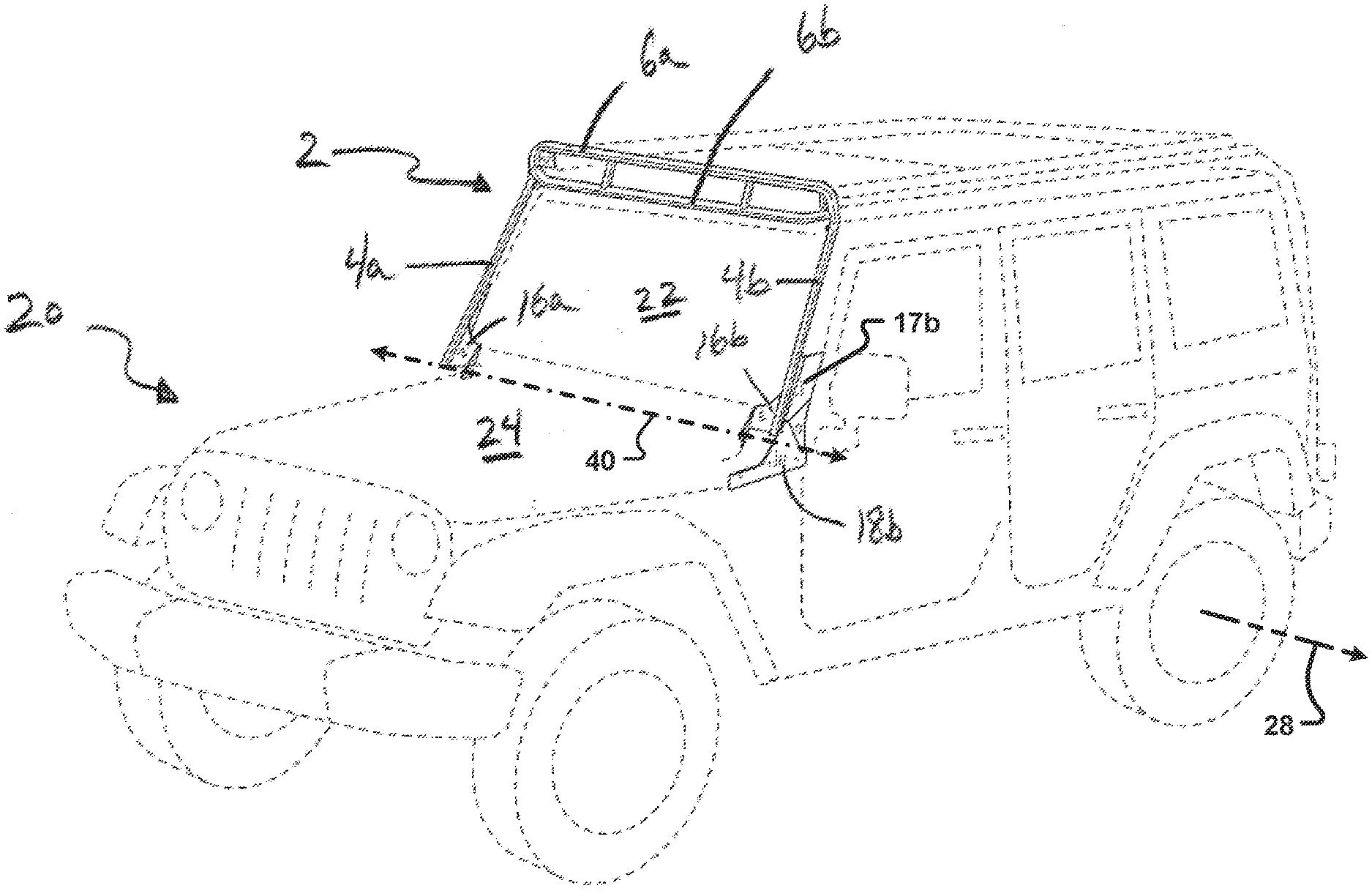
[0031] FIG. 1 is a front perspective view of a rack member for a vehicle according to one embodiment of the present disclosure, the rack member configured to be rotatably interconnected to a front portion of the vehicle.
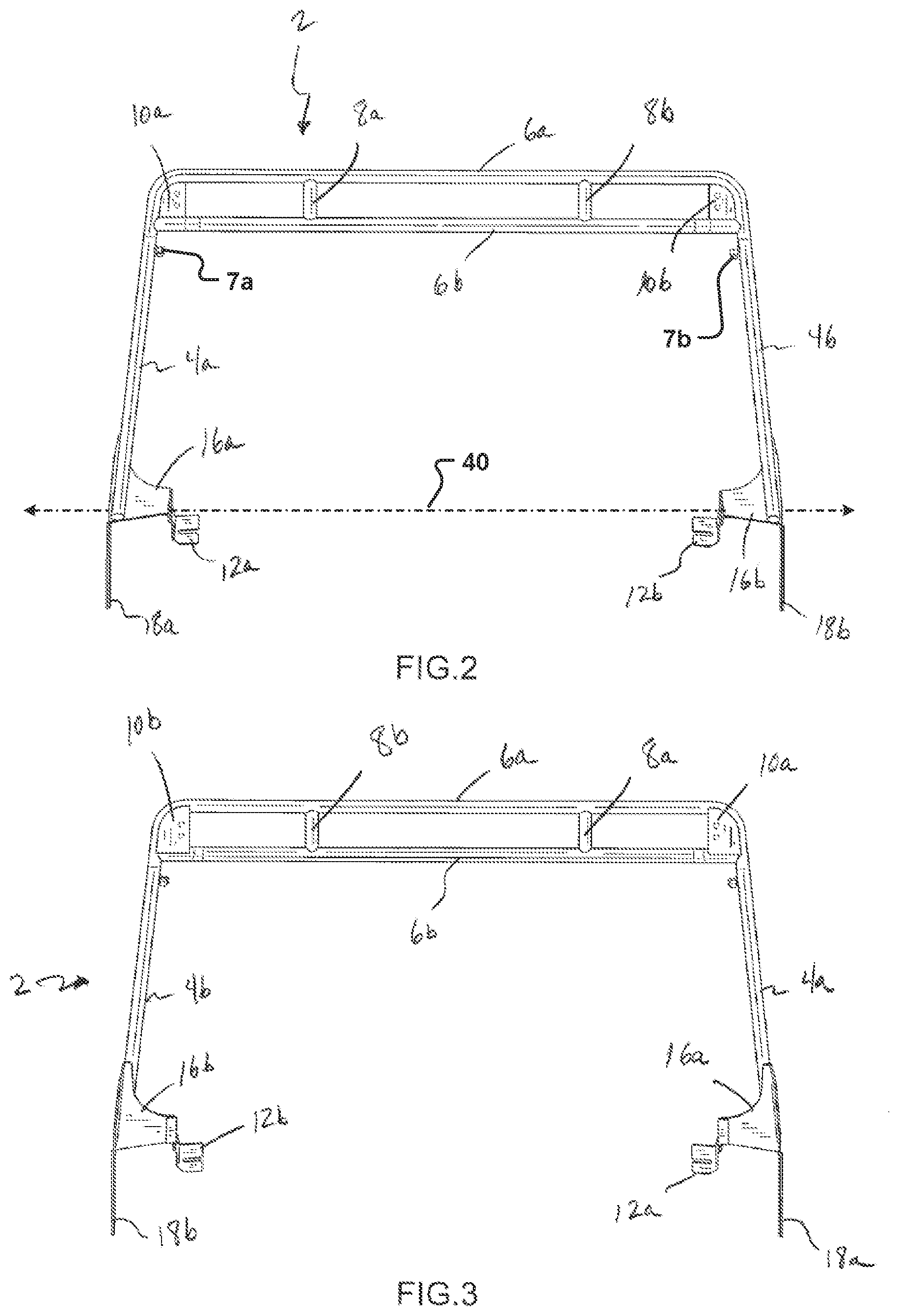
[0032] FIG. 2 is a front elevation view of the rack member according to the embodiment of FIG. 1.
[0033] FIG. 3 is a rear elevation view of the rack member according to the embodiment of FIG. 1.
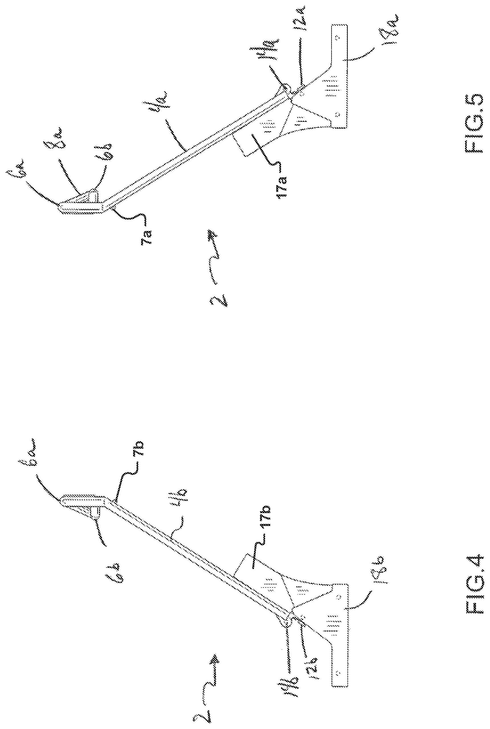
[0034] FIG. 4 is a right elevation view of the rack member according to the embodiment of FIG. 1.
[0035] FIG. 5 is a left elevation view of the rack member according to the embodiment of FIG. 1.
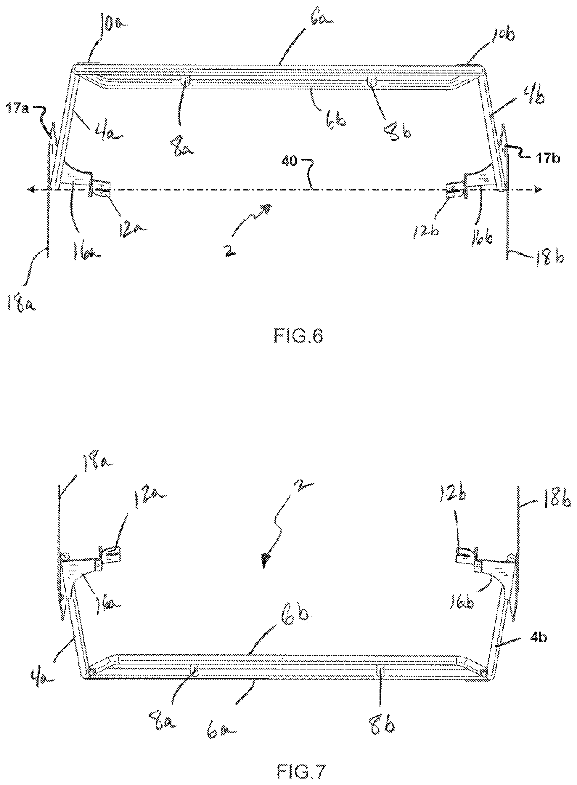
[0036] FIG. 6 is a top plan view of the rack member according to the embodiment of FIG. 1.
[0037] FIG. 7 is a bottom plan view of the rack member according to the embodiment of FIG. 1.
[0038] FIG. 8 is a perspective view of the rack member of the embodiment of FIG. 1 provided in combination with a vehicle.
[0039] FIG. 9 is a perspective view of a bracket member of a rack member according to an embodiment of the present disclosure.
[0040] FIG. 10 is a bottom perspective view of the bracket member according to the embodiment of FIG. 9.
[0041] FIG. 11 is a front elevation view of the bracket member according to the embodiment of FIG. 9.
[0042] FIG. 12 is a rear elevation view of the bracket member according to the embodiment of FIG. 9.
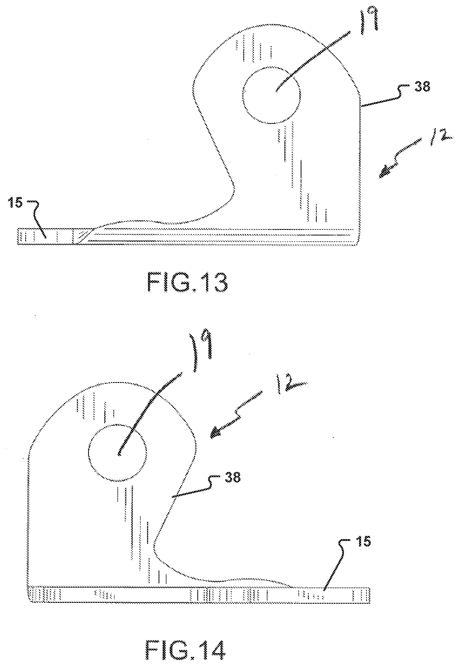
[0043] FIG. 13 is a right elevation view of the bracket member according to the embodiment of FIG. 9.
[0044] FIG. 14 is a left elevation view of the bracket member according to the embodiment of FIG. 9.
[0045] FIG. 15 is a top plan view of the bracket member according to the embodiment of FIG. 9.
[0046] FIG. 16 is a bottom plan view of the bracket member according to the embodiment of FIG. 9.
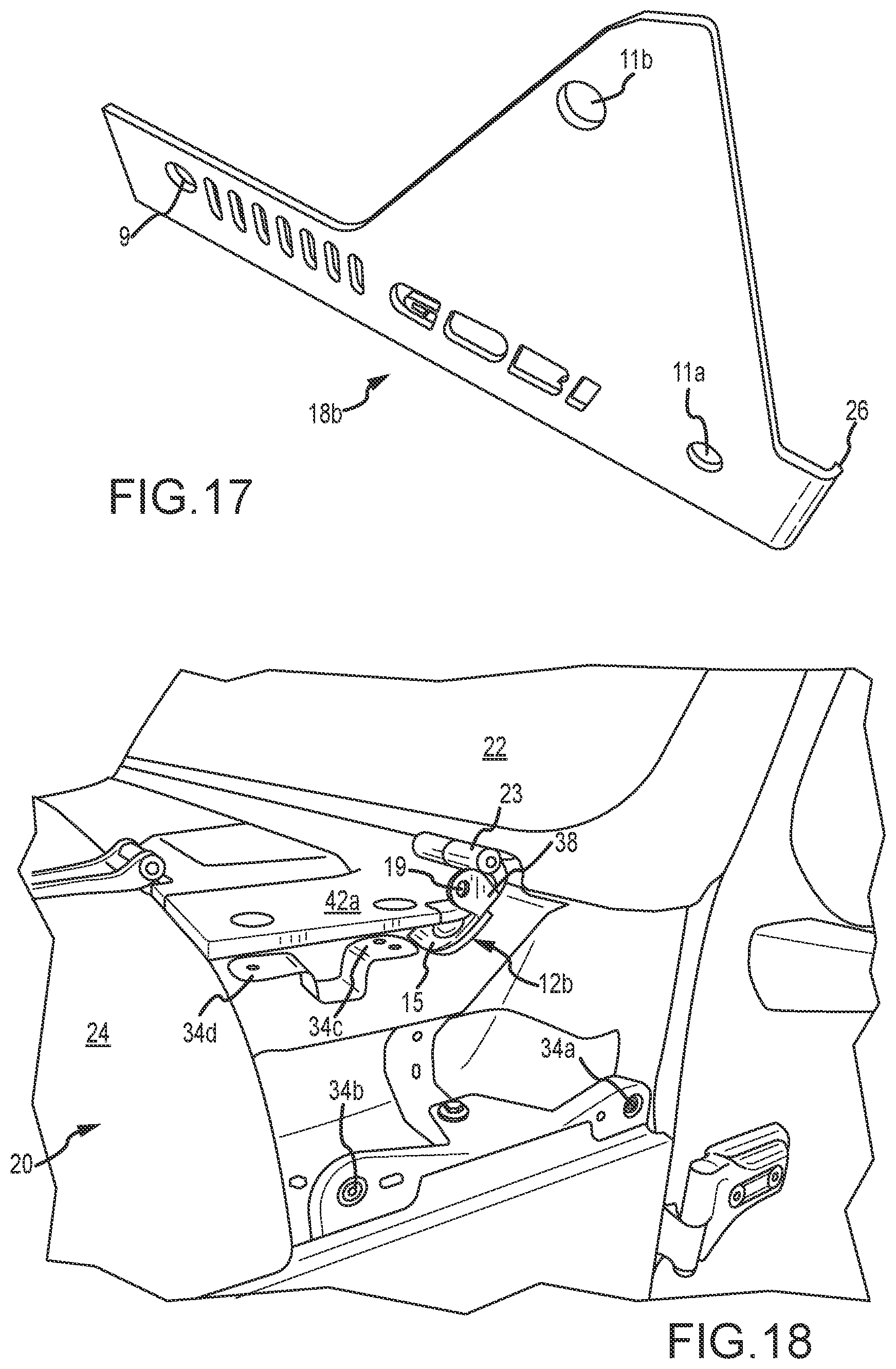
[0047] FIG. 17 is a perspective view of a mounting bracket of the rack member according to one embodiment of the present disclosure.
[0048] FIG. 18 is a perspective view of a bracket member according to one embodiment of the present disclosure and illustrating a portion of the vehicle with some of the cowling removed to facilitate interconnect of the bracket member to a vehicle.
[0049] FIG. 19 is an expanded perspective view of the bracket member of the embodiment of FIG. 18 interconnected to the vehicle.
[0050] FIG. 20 is yet another perspective view of the bracket member of FIG. 18 interconnected to the vehicle.
[0051] FIG. 21A is a perspective view of a support strap of one embodiment of the present disclosure.
[0052] FIG. 21B is a perspective view illustrating interconnection of the support strap of FIG. 21A to a vehicle.
[0053] FIG. 21C is another perspective view illustrating interconnection of the support strap of FIG. 21A to a vehicle proximate to a hinge of a door of the vehicle.
[0054] FIG. 22 is a perspective view illustrating a portion of the bracket member extending above the cowling portion which has been reinstalled on the vehicle of FIG. 20.
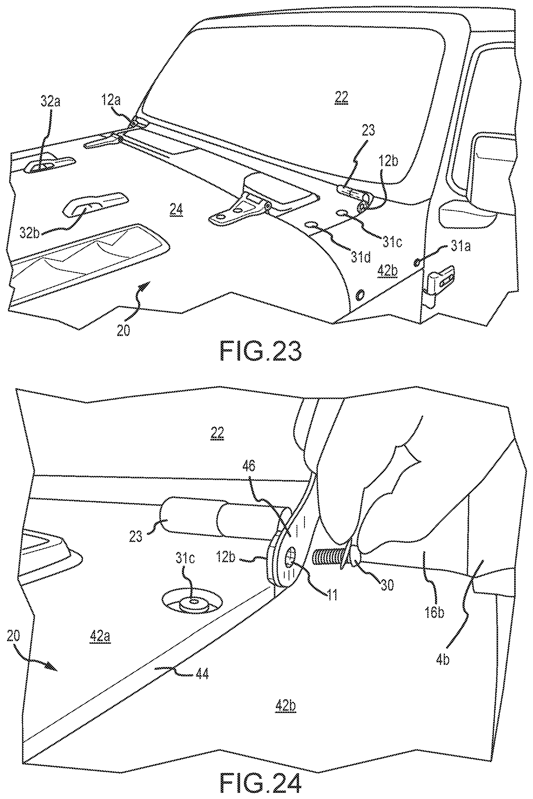
[0055] FIG. 23 is a perspective view showing two bracket members affixed to the vehicle of FIG. 18.
[0056] FIG. 24 is yet another perspective view generally illustrating the rack member being pivotally interconnected to a bracket member affixed to a vehicle.
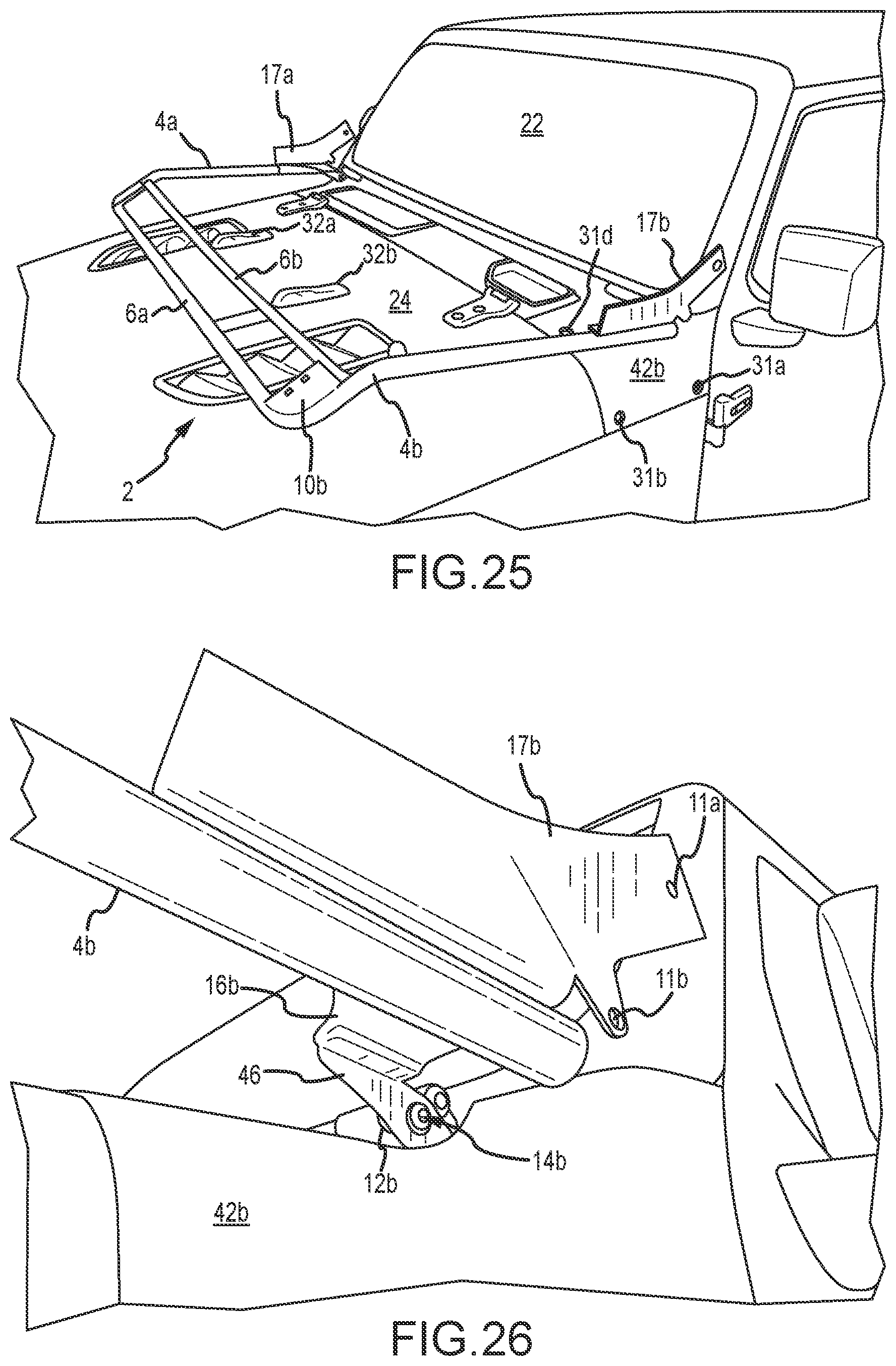
[0057] FIG. 25 is a front perspective view of the vehicle of FIG. 24 showing the rack member of the present disclosure pivotally affixed to the bracket members and illustrating the rack member in a second position of use proximate to the vehicle hood.
[0058] FIG. 26 is another perspective view of the vehicle and the rack member of FIG. 25.
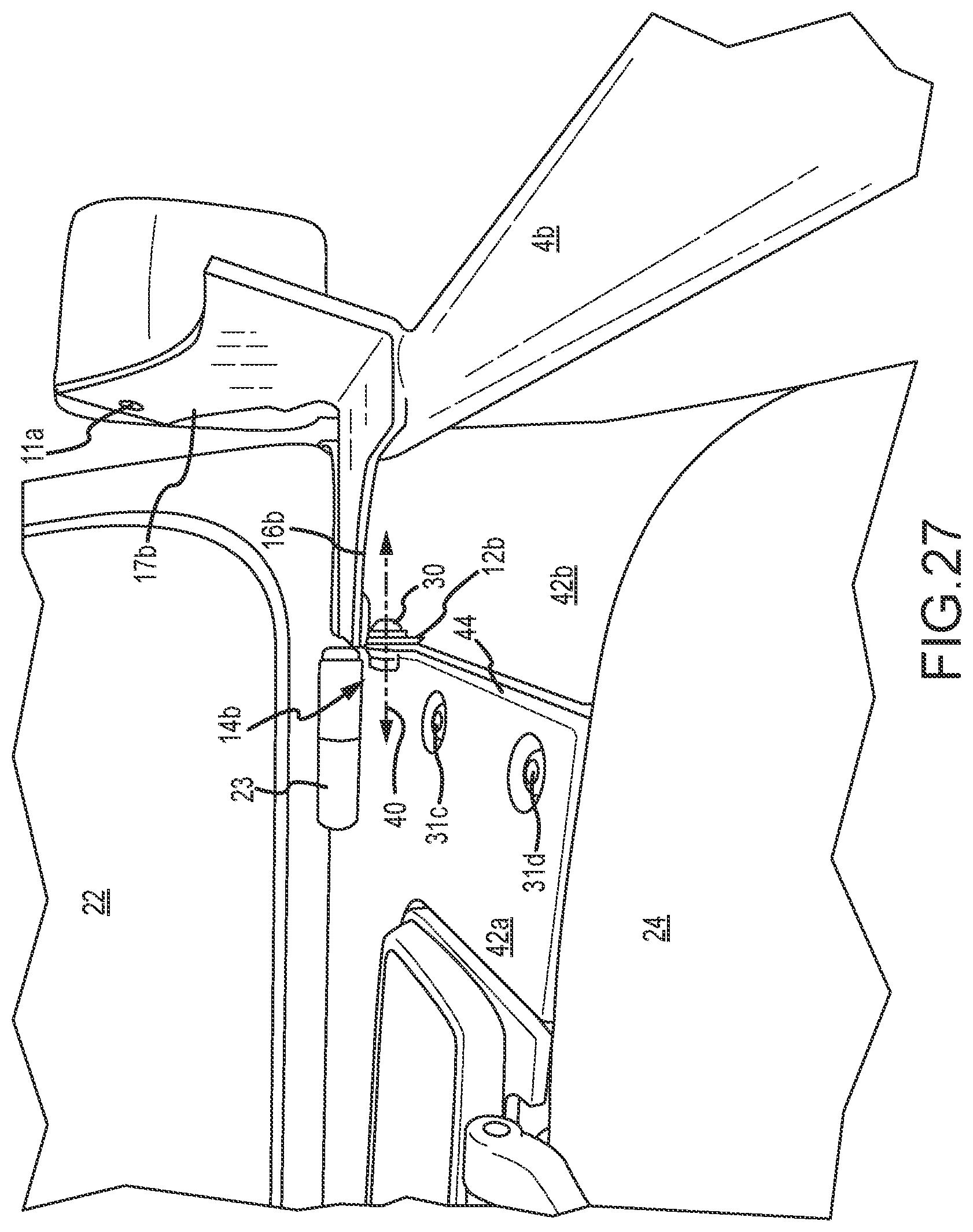
[0059] FIG. 27 is yet another perspective view of the vehicle and the rack member of FIG. 26.
[0060] FIGS. 28-29 are perspective views illustrating installation of a mounting bracket to the rack member and the vehicle of FIG. 27.
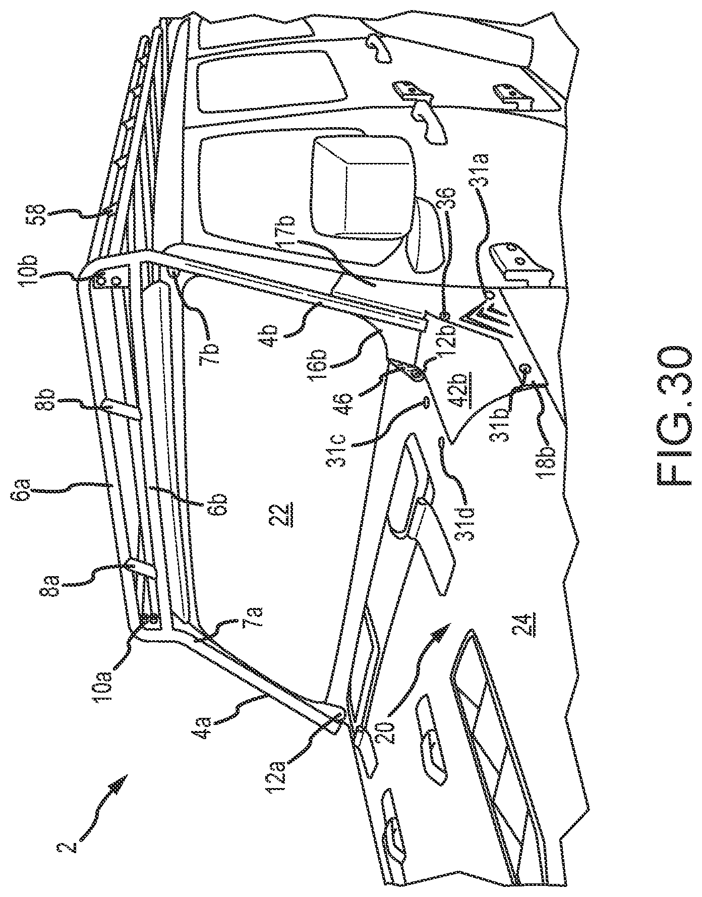
[0061] FIG. 30 is a perspective view of a rack member installed on a vehicle according to one embodiment of the present disclosure and illustrating a roof rack interconnected to the rack member.
[0062] Similar components and/or features may have the same reference number. Components of the same type may be distinguished by a letter following the reference number. If only the reference number is used, the description is applicable to any one of the similar components having the same reference number.
[0063] To assist in the understanding of the present invention the following list of components and associated numbering found in the drawings is provided herein:
TABLE-US-00001 Number Component 2 Rack member 4a First support member 4b Second support member 6a First horizontal support 6b Second horizontal support 7 Contact member 8 Stabilizing members 9 Aperture 10 Attachment plates 11 Aperture 12 Bracket members 13 Slot of bracket member 14 Pivot points 15 Clamp plate portion of bracket member 16 Support member 17 Support member 18 Mounting brackets 19 Eyelet (or through-hole) of bracket member 20 Vehicle 22 Windshield 23 Hinge associated with vehicle windshield 24 Hood 26 Catch of mounting bracket 28 Wheel axis of the vehicle 30 Fastener or Bolt 31 Cowling fastener 32 Support pads of vehicle hood 34 Cowling aperture 36 Fastener 38 Transverse portion of a bracket member 40 Pivot Axis of rotation (or pivot axis of the bracket members) 42 Cowling or exterior trim member of the vehicle 44 Gap between trim members 46 Flange of support member 48 Support strap 50 First portion of strap 52 Second portion of strap 54 Apertures 56 Hinge bolt 57 Door hinge 58 Roof rack
DETAILED DESCRIPTION
[0064] As shown in FIGS. 1-8, a rack member 2 for a vehicle 20 is provided. The rack member 2 comprises first and second 4a, 4b support members that are operable and intended to extend along a windshield 22 of a vehicle 20 (for example). An upper portion of the rack member 2 comprises first and second supports 6a, 6b. The supports 6 are configured to be generally horizontal when the rack member 2 is interconnected to a vehicle as generally illustrated in FIG. 8. Stabilizing members 8a, 8b can optionally be provided. The stabilizing members 8 are generally interconnected to the supports 6. Although two stabilizing members 8a, 8b are provided, it will be recognized that any number of stabilizing members can be provided, including no stabilizing members. Additionally, or alternatively, attachment plates 10a, 10b can provided to selectively secure the rack member 2 to additional rack features or to a roof rack 58.
[0065] The rack member 2 can optionally include contact members 7. In one embodiment, the contact members 7 are configured to engage the vehicle proximate to the windshield 22. The contact members 7 can comprise a soft or elastomeric material, such as a rubber or a plastic. In operation, after the rack member 2 is interconnected to the vehicle in the first position of use, the contact members abut the vehicle and prevent marring or scratching by the rack member. Optionally, the contact members 7 can be compressible or resiliently-deflectable.
[0066] A lower portion of the rack member 2 is connectable to a vehicle 20 proximal to a vehicle's hood 24 and/or cowling 42. The rack member 2 comprises first and second bracket members 12a, 12b that can be pivotally connected to the rack member 2. The bracket members 12a, 12b are selectively securable to preexisting components of a vehicle 20. Accordingly, in one embodiment, the rack member 2 can be interconnected to the vehicle without drilling or cutting the vehicle.
[0067] The bracket members 12 are preferably configured to extend at least partially above the hood 24 of the vehicle and provide a point of interconnection for additional rack member components. The bracket members 12a, 12b further provide pivot points 14a, 14b which define a pivot axis 40 proximal to and above the hood 24. In this manner, the rack member 2 can be attached to the bracket members 12 in a rotatable manner. More specifically, the bracket members 12 can include an eyelet or through-hole 19 (illustrated in FIG. 9) configured to receive a fastener (such as a bolt 30 illustrated in FIGS. 24 and 27) which defines the pivot point 14 and pivot axis 40.
[0068] Support members 16a, 16b, 17a, 17b extend from the support members 4a, 4b and provide structural support to the rack member 2. The support members 16 are adapted to be interconnected to the bracket members 12. The first support member 16a can extend from the first support member 4a inwardly toward the second support member 16b.
[0069] An upper edge of the support members 16 can have an arcuate shape. Optionally, the upper edge has a shape similar to bottom corners of a windshield 22. In this manner, the rack member 2 can minimize visual obstructions to a driver of the vehicle 20.
[0070] In one embodiment, a flange 46 (best seen in FIG. 24) extends from each of the support members 16. The flange 46 is adapted to interconnect the rack member 2 to the bracket members 12. Optionally, the flanges 46 are approximately parallel. In one embodiment the flange can have an aperture 11 for a fastener 30 to interconnect the flange 46 to a bracket member 12 such as generally illustrated in FIG. 24. Alternatively, the flange 46 can include a bolt that can extend through the through-hole 19 of a bracket member 12.
[0071] The support members 17 can be oriented approximately perpendicular to the support member 16. In one embodiment, support members 16, 17 are formed of a single piece of material such as generally illustrated in FIG. 27. Alternatively, the support members 16, 17 are separately formed. The support members 17 generally extend rearwardly away from the support members 4. Optionally, the support members 17a, 17b are approximately parallel. The support members may include apertures 11 (illustrated in FIG. 26) to secure the support members 17 to the vehicle.
[0072] Mounting brackets 18a, 18b are provided on either side of the rack member 2. The mounting brackets 18 can be secured to the rack member 2 by one or more fasteners, such as screws or bolts. For example, the mounting brackets 18 can include two or more apertures 11 to receive fasteners. As generally illustrated in FIG. 28-30, the apertures 9, 11a of the mounting brackets 18 can receive fasteners 31 to selectively secure the brackets 18 to a vehicle 20. Optionally, aperture 9 can receive a fastener 31b to secure the mounting bracket 18 directly to the vehicle, as generally illustrated in FIG. 30. The mounting brackets 18a, 18b of the depicted embodiments are operable to extend along a side portion or quarter panel of a vehicle 20.
[0073] Each mounting bracket 18 can be affixed to one of the support members 17. Apertures 11b through the mounting bracket 18 can receive a fastener 36 that extends through a corresponding aperture 11b of a support member 17, such as generally illustrated in FIG. 28.
[0074] In one embodiment, illustrated in FIG. 17, the mounting brackets 18 can include a hook or catch 26. The catch 26 may be proximate to an edge of the mounting bracket 18 and extend transverse to a plane defined by the mounting bracket. Referring now to FIG. 29, when the mounting bracket 18 is interconnected to the vehicle 20, the catch 26 can engage a rearward edge of the support bracket 17. In this manner, the catch 26 can prevent (or reduce) inadvertent or unintended movement of the rack member 2. In one embodiment, the catch 26 has a length extending from the mounting bracket 18 that is less than the thickness of support bracket 17. Accordingly, the catch 26 can be spaced from the vehicle when the mounting bracket is affixed to the vehicle.
[0075] Although certain embodiments of the present disclosure provide an axis of rotation 40 or hinge point 14 for the rack member 2 being provided at or through the bracket members 12 and support members 16, other embodiments contemplate an alternative or additional hinge point provided elsewhere in the system or rack member 2. For example, it is contemplated that each of the first and second support members 4a, 4b comprise a hinge along their length to allow for rotation of an upper portion of the members 4a, 4b and the upper portion of the rack member 2.
[0076] In some embodiments, the rack member 2 is operable to rotate about an axis defined by a fastener 31b through apertures 9 in the mounting brackets 18. For example, various supports and fasteners may be selectively removed or loosened such that the rack member 2 is rotatable about a pin or fastener 31b secured through apertures 9 of the mounting brackets 18. One of skill in the art will recognize that the scope of the invention(s) of the present disclosure are not limited to a particular hinge or pivot point, and that various pivot points may be provided without deviating from the scope and spirit of the disclosure.
[0077] The rack member 2 of the embodiment of FIGS. 1-8 is operable to selectively hinge forward. Specifically, the rack member 2 is selectively rotatable by uncoupling a connection between the attachment plates 10a, 10b and a connected feature (e.g. an additional rack member or a vehicle, see FIG. 30 wherein attachment plates 10a, 10b are coupled to a roof rack 58 with fasteners), uncoupling the connection between the mounting brackets 18a, 18b and the respective support members 17a, 17b by removing the fastener 36, removing fastener 31a from the cowling 42, and rotating the upper portion of the rack member 2 forward about an axis of rotation 40 that extends between opposing pivot points 14a, 14b. In one embodiment, the axis of rotation 40 is substantially parallel to a wheel axle or axis of rotation 28 of the wheels of the vehicle 20. The rack member 2 is thus capable of a forwardly-hinging movement such that the rack member 2 and a windshield 22 of the vehicle 20 may be lowered or rotated to a position proximal to the hood 24 of the vehicle 20.
[0078] FIGS. 9-16 are various views of a bracket member 12 according to one embodiment of the present disclosure. As shown, the bracket member 12 comprises a bracket that is selectively securable to a portion of a vehicle 20. In one embodiment, the bracket member 12 generally comprises a clamp plate portion 15 and a transverse portion 38.
[0079] The transverse portion 38 can be oriented approximately perpendicular to the clamp plate portion 15. The transverse portion 38 generally includes an aperture or through-hole 19 which defines the pivot axis 40. The through-hole 19 is formed in the transverse portion 38 such that it extends at least partially above the exterior surface of the vehicle 20 (such as one or more pieces of vehicle cowling 42) when the bracket member 12 is secured to the vehicle. In on embodiment, the transverse portion 38 is configured to extend from and above a gap 44 between exterior metal trim members (such as portions of the cowling 42) of the vehicle. Optionally, the upper portion of the transverse portion 38 is rounded or arcuately shaped.
[0080] The through-hole 19 can be aligned with an aperture 11 through a flange 46 of a support member 16 as generally illustrated in FIG. 24. In this manner, a fastener 30 can extend through the through-hole 19 and the flange aperture 11 to pivotally interconnect the rack member 2 to the bracket member 12 and the vehicle.
[0081] The clamp plate portion 15 is configured to be interconnected to a vehicle, such as generally illustrated in FIGS. 18-19. In some embodiments, the clamp plate portion 15 of the bracket member 12 is secured to the vehicle by a fastener 30a. Accordingly, the clamp plate portion 15 can include a feature 13 to receive the fastener. For example, the bracket member 12 can comprise an aperture 13 within the clamp plate portion 15. In one embodiment, the aperture 13 is elongated to define a slot 13. The slot 13 is operable to receive a shaft of a fastener 30a while a head and/or washer can abut the clamp plate portion 15. The nut, washer and/or other fastener 30a is operable to provide a compressive force on the clamp plate portion 15 and secure the bracket member 12 in a desired position with respect to a vehicle 20 such as generally illustrated in FIG. 22. The slot 13 facilitates aligning the bracket member 12 with the vehicle 20.
[0082] In one embodiment, the slot 13 is adapted to engage a fastener 30a associated with a hinge 23 of the vehicle. More specifically, when a portion of cowling 42 has been removed from the vehicle (as generally illustrated in FIGS. 19-20), the hinge fastener 30a can be loosened without removing the fastener from the vehicle. The clamp plate portion 15 can then slide between the head of the fastener 30a and be secured to the vehicle by tightening the fastener 30a.
[0083] In some embodiments, the desired position of the bracket member 12 comprises a position wherein a portion of the bracket member 12, such as the transverse portion 38 including the through-hole 19, extends above a hood 24 and/or cowling 42 of a vehicle (such as generally illustrated in FIG. 22). This position, and the structure of the bracket member 12 shown and described herein provide for an attachment and pivot axis 40 for a rack member 2 that is above and proximal to a top surface of a vehicle hood 24 (as shown in FIG. 8, for example). The bracket member 12 preferably comprises a metal, such as steel.
[0084] To interconnect the rack member 2 to a vehicle, fasteners 31 are removed from the vehicle to remove a portion of the cowling 42b as generally illustrated in FIG. 18. In this manner, with the cowling removed, the screw or bolt 30a associated with a hinge 23 (illustrated in FIG. 19) can be loosened. The bracket member 12 can then slide into position between a head of the bolt 30a and the hinge. The bolt 30a can then be re-tightened to secure the bracket member 12 to the vehicle as generally illustrated in FIGS. 19-22.
[0085] Referring now to FIGS. 21A-21C, a support strap 48 can optionally be interconnected to the vehicle. The support strap 48 can be formed from piece of metal material, such as a thin piece of steel. In one embodiment, the support strap 48 generally includes a first portion 50 and a second portion 52. Apertures 54 can be formed through the first and second portions 50, 52. Optionally, aperture 54B can be elongated, such as to form a closed slot, to facilitate adjustment of the support strap 48 relative to the vehicle.
[0086] The first portion 50 can be oriented approximately perpendicular to the second portion 52. Optionally, the support strap 48 is folded or bent one or more times such that the first and second portions 50, 52 are in a predetermined orientation.
[0087] To interconnect the support strap 48 to a vehicle, a screw or bolt 56 associated with a hinge 57 of a front door of the vehicle can be removed. The second portion 52 of the support strap 48 can then be positioned proximate to the door hinge. A first aperture 54a of the support strap 48 can be aligned with an aperture 34a for the cowling (generally illustrated in FIG. 18) that was previously removed to install the bracket members 12.
[0088] Optionally, the fastener 31a removed from aperture 34a can be reinstalled through the first aperture 54a of the support strap 48 and the aperture 34a in the vehicle as shown in FIG. 21B. A second aperture 54b of the support strap 48 can be aligned with an aperture for the hinge bolt 56. The hinge bolt 56 can then be threaded back into the vehicle through the second aperture 54b of the support strap 48 and a plate of the hinge 57 as generally illustrated in FIG. 21C. The cowling 42b can then be reinstalled using only the upper two fasteners 31c, 31d as generally illustrated in FIG. 28.
[0089] Referring now to FIG. 24, the rack member 2 can be pivotally interconnected to the bracket members 12 with a fastener 30. More specifically, the fastener can extend through an aperture 11 in the flange 46 of the support member 16 and through the through-hole 19 of the bracket member 12 to rotatably interconnect the rack member 2 to the vehicle 20.
[0090] Referring now to FIG. 28, the mounting bracket 18 can be interconnected to the rack member 2 with another fastener 36. More specifically, aperture 11b of the mounting plate 18 can be aligned with aperture 11b of the support member 17. A fastener 36 can then be secured in the apertures 11b to interconnect the mounting bracket 18 to the rack member 2.
[0091] The mounting bracket 18 can also be releasably interconnected to the vehicle 20 to provide additional stability or support to the rack member 2. Aperture 11a of the mounting bracket 18 can be aligned with aperture 11a of the support member 17 as well as the cowling aperture 34a (illustrated in FIG. 18). Similarly, aperture 9 of the mounting bracket 18 can be aligned with cowling aperture 34b (illustrated in FIGS. 18 and 28). Cowling fastener 31a can then be positioned in apertures 11a, 34a as generally illustrated in FIG. 29. If the optional support strap 48 is used as described in FIGS. 21A-21C, the cowling fastener 31a will also extend through the first aperture 54A of the support strap 48 to provide additional support to the rack member 2. The catch 26 of the mounting bracket 18 can be positioned to engage a rearward edge of the support member 17 (as shown in FIG. 29) as the fastener 31a is threaded into the apertures 11a, 34a. Another cowling fastener 31b can be positioned in apertures 9, 34b as shown in FIG. 30.
[0092] As shown in FIG. 23, the vehicle hood 24 may include support pads 32a, 32b that selectively receive and support a windshield 22 in a lowered position. The support members 4 can have a length such that the horizontal supports 6 do not rest on the support pads 32 when the rack 2 is rotated to the second position proximate to the vehicle hood as generally illustrated in FIG. 25. Accordingly, the support pads 32 can cushion the windshield 22 with interference from the rack member 2.
[0093] As shown in FIG. 19, a preexisting hinge 23 is provided with the vehicle 20 proximal to the cowling 42 and below the windshield 22. This hinge is provided to allow the windshield 22 to rotate toward the hood 24. Embodiments of the present disclosure contemplate that the depicted hinge 23 is also provided as the pivot point or point of rotation for the rack member 2. Specifically, it is contemplated that a bracket member 2 may be provided with the preexisting hinge 23 that operates in a similar manner as the depicted bracket member 12. Additionally, it is contemplated that the hinge bolt may be extended to provide extra length to accommodate a bracket and/or directly receive the rack member(s) (at 16a, 16b, for example).
[0094] FIGS. 25-27 provide various views of an installed rack member 2 in a second (or lowered) position, thus enabling lowering of the vehicle's windshield 22 toward the hood 24.
[0095] FIGS. 28-29 illustrate installation of a mounting bracket 18 according to one embodiment of the present disclosure. A fasteners 31a can be positioned through apertures 11a of the mounting bracket 18 and the support member 17 and into a preexisting aperture 34a for the cowling 42b in the vehicle 20. Another fastener 31b can extend through aperture 9 of the mounting bracket 18 and into an existing aperture 34b of the vehicle. Because the fasteners 34a, 34b are secured in existing vehicle apertures 31a, 31b, no new holes are required to be formed in the vehicle to interconnect the rack member 2.
[0096] FIG. 30 depicts the rack member 2 on a vehicle 20. The rack member 2 and the windshield 22 are illustrated in the upright or first position of use. A roof rack 58 is shown connected to the attachment plates 10 of the rack member 2.
[0097] Various features and embodiments of vehicle racks devices are provided herein. It will be recognized, however, that various features are not necessarily specific to certain embodiments and may be provided on any one or more embodiments. The present disclosure and embodiments provided herein are not mutually exclusive and may be combined, substituted, and omitted. The scope of the invention(s) provided herein is thus not limited to any particular embodiment, drawing, or particular arrangement of features.
[0098] While various embodiments of the present disclosure have been described in detail, it is apparent that modifications and alterations of those embodiments will occur to those skilled in the art. However, it is to be expressly understood that such modifications and alterations are within the scope and spirit of the present disclosure. Further, the invention(s) described herein are capable of other embodiments and of being practiced or of being carried out in various ways. In addition, it is to be understood that the phraseology and terminology used herein is for the purposes of description and should not be regarded as limiting. The use of "including," "comprising," or "adding" and variations thereof herein are meant to encompass the items listed thereafter and equivalents thereof, as well as, additional items.
* * * * *
D00000
D00001
D00002
D00003
D00004
D00005
D00006
D00007
D00008
D00009
D00010
D00011
D00012

D00013

D00014

D00015
D00016
D00017
D00018

D00019
XML
uspto.report is an independent third-party trademark research tool that is not affiliated, endorsed, or sponsored by the United States Patent and Trademark Office (USPTO) or any other governmental organization. The information provided by uspto.report is based on publicly available data at the time of writing and is intended for informational purposes only.
While we strive to provide accurate and up-to-date information, we do not guarantee the accuracy, completeness, reliability, or suitability of the information displayed on this site. The use of this site is at your own risk. Any reliance you place on such information is therefore strictly at your own risk.
All official trademark data, including owner information, should be verified by visiting the official USPTO website at www.uspto.gov. This site is not intended to replace professional legal advice and should not be used as a substitute for consulting with a legal professional who is knowledgeable about trademark law.