Electronic Venting In A Saddle Fuel Tank
Mills; Vaughn K.
U.S. patent application number 17/092530 was filed with the patent office on 2021-02-25 for electronic venting in a saddle fuel tank. This patent application is currently assigned to Eaton Intelligent Power Limited. The applicant listed for this patent is Eaton Intelligent Power Limited. Invention is credited to Vaughn K. Mills.
| Application Number | 20210053437 17/092530 |
| Document ID | / |
| Family ID | 1000005199261 |
| Filed Date | 2021-02-25 |


| United States Patent Application | 20210053437 |
| Kind Code | A1 |
| Mills; Vaughn K. | February 25, 2021 |
ELECTRONIC VENTING IN A SADDLE FUEL TANK
Abstract
A fuel tank system controlled by a control module and constructed in accordance to one example of the present disclosure includes a saddle fuel tank, and a venting assembly. The saddle fuel tank has a first lobe and a second lobe extending on opposite ends of a recessed central portion. The venting assembly comprises a first vent line, a second vent line and a rotary actuator. The first vent line has a first vent port located in the first lobe of the saddle fuel tank near a top portion of the saddle fuel tank above the recessed central portion. The second vent line has a second vent port located in the second lobe of the saddle fuel tank near a top portion of the saddle fuel tank above the recessed central portion.
| Inventors: | Mills; Vaughn K.; (Chelsea, MI) | ||||||||||
| Applicant: |
|
||||||||||
|---|---|---|---|---|---|---|---|---|---|---|---|
| Assignee: | Eaton Intelligent Power
Limited Dublin IE |
||||||||||
| Family ID: | 1000005199261 | ||||||||||
| Appl. No.: | 17/092530 | ||||||||||
| Filed: | November 9, 2020 |
Related U.S. Patent Documents
| Application Number | Filing Date | Patent Number | ||
|---|---|---|---|---|
| 15782302 | Oct 12, 2017 | 10828982 | ||
| 17092530 | ||||
| PCT/US2016/027226 | Apr 13, 2016 | |||
| 15782302 | ||||
| 62146660 | Apr 13, 2015 | |||
| 62161339 | May 14, 2015 | |||
| Current U.S. Class: | 1/1 |
| Current CPC Class: | B60K 2015/03118 20130101; Y10T 137/86212 20150401; F02M 2025/0863 20130101; F16K 31/52416 20130101; B60K 15/035 20130101; B60K 2015/03276 20130101; F16K 31/52408 20130101; B60K 15/03519 20130101; B60K 2015/03533 20130101; F02M 37/0094 20130101; B60K 2015/03302 20130101; B60K 2015/03561 20130101; F16K 31/0651 20130101; B60K 2015/03223 20130101; B60K 2015/0319 20130101; Y10T 137/7761 20150401; B60K 2015/03566 20130101; B60K 2015/03217 20130101 |
| International Class: | B60K 15/035 20060101 B60K015/035; F16K 31/524 20060101 F16K031/524; F02M 37/00 20060101 F02M037/00; F16K 31/06 20060101 F16K031/06 |
Claims
1. A fuel tank system controlled by a control module, the fuel tank system comprising: a saddle fuel tank having a first lobe and a second lobe extending on opposite ends of a recessed central portion; a venting assembly comprising: a first vent line having a first vent port located in the first lobe of the saddle fuel tank near a top portion of the saddle fuel tank above the recessed central portion; a second vent line having a second vent port located in the second lobe of the saddle fuel tank near a top portion of the saddle fuel tank above the recessed central portion; and a rotary actuator configured to rotate a cam, the cam selectively translating a first valve configured to open and close the first vent line and a second valve configured to open and close the second vent line, wherein the first and second vent ports are positioned in the respective first and second vent lobes above the first and second valves; and wherein the control module sends a signal to the rotary actuator to rotate the cam and therefore close the first and second vent lines with the respective first and second valves upon reaching a full fuel condition.
2. The fuel tank system of claim 1 wherein the cam is configured to close one of the first and second valves.
3. The fuel tank system of claim 2 wherein the cam is configured to concurrently close the first and second valves.
4. The fuel tank system of claim 1, further comprising the control module, wherein the control module is positioned intermediate the first and second vent ports on the saddle tank.
5. The fuel tank system of claim 4, further comprising: a liquid trap, wherein the first and second vent lines are routed between the respective first and second vent ports and the liquid trap.
6. The fuel tank system of claim 1, further comprising: a fuel level sensor that communicates to the control module a signal corresponding to the full fuel condition.
7. The fuel tank system of claim 6 wherein the fuel level sensor comprises a first fuel level sensor disposed in the first lobe and a second fuel level sensor disposed in the second lobe.
8. The fuel tank system of claim 1 wherein the first and second valves are poppet valves.
9. A fuel tank system controlled by a control module, the fuel tank system comprising: a saddle fuel tank having a first lobe, a second lobe and a recessed central portion positioned between the first and second lobes; a venting assembly comprising: a first vent line having a first vent port located in the first lobe of the saddle fuel tank above the recessed central portion; a second vent line having a second vent port located in the second lobe of the saddle fuel tank above the recessed central portion; and a rotary actuator configured to rotate a cam, the cam selectively moving a first valve that opens and closes the first vent line and a second valve that opens and closes the second vent line, wherein the first and second vent ports are positioned in the respective first and second vent lobes above the first and second valves; and wherein the control module sends a signal to the rotary actuator to rotate the cam and therefore close the first and second vent lines with the respective first and second valves upon reaching a full fuel condition.
10. The fuel tank system of claim 9 wherein the cam is configured to close one of the first and second valves.
11. The fuel tank system of claim 10 wherein the cam is configured to concurrently close the first and second valves.
12. The fuel tank system of claim 9 wherein the control module is positioned intermediate the first and second vent ports on the saddle tank.
13. The fuel tank system of claim 12, further comprising: a liquid trap, wherein the first and second vent lines are routed between the respective first and second vent ports and the liquid trap.
14. The fuel tank system of claim 9, further comprising: a fuel level sensor that communicates to the control module a signal corresponding to the full fuel condition.
15. The fuel tank system of claim 14 wherein the fuel level sensor comprises a first fuel level sensor disposed in the first lobe and a second fuel level sensor disposed in the second lobe.
16. The fuel tank system of claim 9 wherein the first and second valves are poppet valves.
17. A fuel tank system controlled by a control module, the fuel tank system comprising: a saddle fuel tank having a first lobe, a second lobe and a recessed central portion positioned between and below the first and second lobes; a venting assembly comprising: a first vent line having a first vent port located in the first lobe of the saddle fuel tank near a top portion of the saddle fuel tank above the recessed central portion; a second vent line having a second vent port located in the second lobe of the saddle fuel tank near a top portion of the saddle fuel tank above the recessed central portion; and a rotary actuator that rotates a cam, the cam selectively moving a first valve that opens and closes the first vent line and a second valve that opens and closes the second vent line, wherein the first and second vent ports are positioned in the respective first and second vent lobes above the first and second valves; and wherein the control module sends a signal to the rotary actuator to rotate the cam and therefore close at least one of the first and second vent lines with the respective first and second valves based on a full fuel condition.
Description
CROSS-REFERENCE TO RELATED APPLICATIONS
[0001] This application is a continuation of U.S. patent application Ser. No. 15/782,302 filed Oct. 12, 2017, which is a continuation of International Application No. PCT/US2016/027226 filed Apr. 13, 2016, which claims the benefit of U.S. Patent Application No. 62/146,660 filed on Apr. 13, 2015; and U.S. Patent Application No. 62/161,339 filed on May 14, 2015. The disclosures of the above applications are incorporated herein by reference.
FIELD
[0002] The present disclosure relates generally to fuel tanks on passenger vehicles and more particularly to a fuel tank that allows proper venting in a saddle fuel tank.
BACKGROUND
[0003] Proper venting and handling of fuel and fuel vapor is required for fuel tanks. More particularly, fuel tanks must be properly vented for passenger motor vehicles. Furthermore, fuel tanks must properly account for containment of liquid fuel. A fuel tank having a saddle geometry can present challenges for proper venting. Saddle fuel tanks are popular among all-wheel-drive powertrain configurations. A saddle tank has two independent lobes often filled with fuel to different heights in different scenarios. In some examples, the geometry of the saddle tank can cause the fuel tank to incorrectly assume a full fuel condition based on fuel level interaction with existing shut-off valve configurations. While current offerings are satisfactory it would be desirable to provide a system on a saddle fuel tank that vents independently of the volume in either lobe while still accurately determining the total fuel volume in the entire fuel tank.
[0004] The background description provided herein is for the purpose of generally presenting the context of the disclosure. Work of the presently named inventors, to the extent it is described in this background section, as well as aspects of the description that may not otherwise qualify as prior art at the time of filing, are neither expressly nor impliedly admitted as prior art against the present disclosure.
SUMMARY
[0005] A fuel tank system controlled by a control module and constructed in accordance to one example of the present disclosure includes a saddle fuel tank, and a venting assembly. The saddle fuel tank has a first lobe and a second lobe extending on opposite ends of a recessed central portion. The venting assembly comprises a first vent line, a second vent line and a rotary actuator. The first vent line has a first vent port located in the first lobe of the saddle fuel tank near a top portion of the saddle fuel tank above the recessed central portion. The second vent line has a second vent port located in the second lobe of the saddle fuel tank near a top portion of the saddle fuel tank above the recessed central portion. The rotary actuator is configured to rotate a cam. The cam selectively translates a first vent configured to open and close the first vent line and a second valve configured to open and close the second vent line. The first and second vent ports are positioned in the respective first and second vent lobes above the first and second valves. The control module sends a signal to the rotary actuator to rotate the cam and therefore close the first and second vent lines with the respective first and second valves upon reaching a full fuel condition.
[0006] According to additional features, the cam is configured to close one of the first and second valves. The cam can be configured to concurrently close the first and second valves. The control module can be positioned intermediate the first and second vent ports on the saddle tank. The fuel tank system can further include a liquid trap. The first and second vent lines can be routed between the first and second vent ports and the liquid trap. The fuel tank system can further include a fuel level sensor that communicates to the control module a signal corresponding to the full fuel condition. The fuel level sensor can comprise a first fuel level sensor disposed in the first lobe and a second fuel level sensor disposed in the second lobe. The first and second valves can be poppet valves.
[0007] A fuel tank system controlled by a control module and constructed in accordance to another example of the present disclosure includes a saddle fuel tank, and a venting assembly. The saddle fuel tank has a first lobe, a second lobe and a recessed central portion positioned between the first and second lobes. The venting assembly comprises a first vent line, a second vent line and a rotary actuator. The first vent line has a first vent port located in the first lobe of the saddle fuel tank above the recessed central portion. The second vent line has a second vent port located in the second lobe of the saddle fuel tank above the recessed central portion. The rotary actuator is configured to rotate a cam. The cam selectively moves a first valve that opens and closes the first vent line and a second valve that opens and closes the second vent line. The first and second vent ports are positioned in the respective first and second vent lobes above the first and second valves. The control module sends a signal to the rotary actuator to rotate the cam and therefore close the first and second vent lines with the respective first and second valves upon reaching a full fuel condition.
[0008] A fuel tank system controlled by a control module and constructed in accordance to yet another example of the present disclosure includes a saddle fuel tank, and a venting assembly. The saddle fuel tank has a first lobe, a second lobe and a recessed central portion positioned between the first and second lobes. The venting assembly comprises a first vent line, a second vent line and a rotary actuator. The first vent line has a first vent port located in the first lobe of the saddle fuel tank near a top portion of the saddle fuel tank above the recessed central portion. The second vent line has a second vent port located in the second lobe of the saddle fuel tank near a top portion of the saddle fuel tank above the recessed central portion. The rotary actuator rotates a cam. The cam selectively moves a first valve that opens and closes the first vent line and a second valve that opens and closes the second vent line. The first and second vent ports are positioned in the respective first and second vent lobes above the first and second valves. The control module sends a signal to the rotary actuator to rotate the cam and therefore close the first and second vent lines with the respective first and second valves upon reaching a full fuel condition.
BRIEF DESCRIPTION OF THE DRAWINGS
[0009] The present disclosure will become more fully understood from the detailed description and the accompanying drawings, wherein:
[0010] FIG. 1 is a schematic illustration of a saddle fuel tank incorporating an electronic venting system and constructed in accordance to one example of the present disclosure;
[0011] FIG. 2 is a schematic illustration of a saddle fuel tank constructed in accordance to one example of prior art;
[0012] FIG. 3 is a schematic illustration of a saddle fuel tank constructed in accordance to another example of prior art;
[0013] FIG. 4 is a schematic illustration of the fuel tank of FIG. 1;
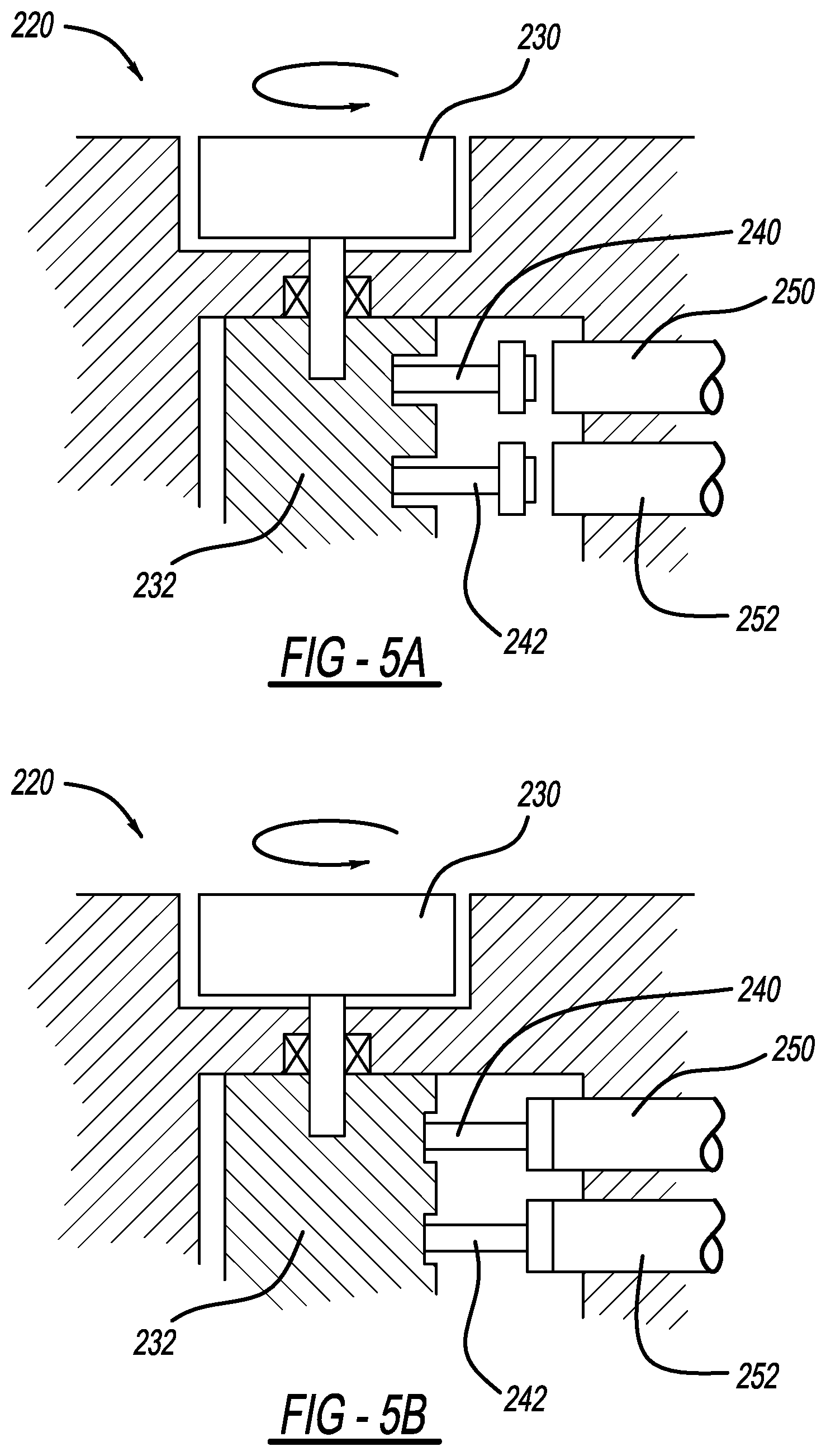
[0014] FIG. 5A is a schematic illustration of a cam driven tank venting assembly constructed in accordance to additional features of the present disclosure and shown with the two vents in an open position; and
[0015] FIG. 5B is a schematic illustration of the cam driven tank venting assembly of FIG. 5A and shown with the two vents in a closed position.
DETAILED DESCRIPTION
[0016] With initial reference now to FIG. 2, a fuel tank constructed in accordance to one example of prior art is shown and generally identified at reference 10. Fuel tank 10 is a saddle fuel tank having a first lobe 12 and a second lobe 14. The first lobe 12 is configured as a fuel inlet side. During a refueling event, the fuel is filled into the first lobe 12 before reaching a spillover point 16 where it spills or cascades into the second lobe 14. The second lobe 14 includes a fuel limit vent valve (FLVV) 20 having a shut off point 22. The FLVV 20 controls the shut off point of fuel during refueling based on a relationship between the level of fuel and the shut off point 22. The second lobe 14 is where the fuel tank 10 controls the shut-off height of the fuel during refueling. However, in some instances after shut-off the first lobe 12 and the second lobe 14 can have unequal fuel heights.
[0017] As shown in FIG. 3, a fuel tank 10A includes a venturi or slave pump 30. The slave pump 30 can be incorporated in the first lobe 12A to pump fuel from the first lobe 12A to the second lobe 14A. The second lobe 14A includes a fuel pump 34. The slave pump 30 will pump fuel from the first lobe 12A to the second lobe 14A to level out the first and second lobes 12A and 14A. In this regard, the slave pump 30 will operate to keep a similar level of fuel in both of the first and second lobes 12A, 14A. In another configuration, the slave pump 30 may pump fuel from the second lobe 14A to the first lobe 12A. In some scenarios however, the fuel level will then be above the FLVV shut off point 22 (FIG. 2). The shut off point 22 is submerged under fuel. When an amount of fuel is used and a refuel event is desired, the FLVV 20 may still remain shut off even if the tank is less than full. In such a scenario the FLVV 20 has not reopened and therefore no vent pathway is available to allow refueling.
[0018] Turning now to FIGS. 1 and 4, a fuel tank system constructed in accordance to the present disclosure is shown and generally identified at reference numeral 110. The fuel tank system 110 includes an electronic venting system 112 configured on a saddle fuel tank 114. The saddle fuel tank 114 includes a first lobe 116 and a second lobe 118. The first lobe 116 and second lobe 118 can generally define bulbous portions extending on opposite sides of a recessed central portion 119. The electronic venting system 112 can include a solenoid assembly 120 including a first solenoid 122 and a second solenoid 124.
[0019] A control module 130 can control the first and second solenoids 122 and 124. The first solenoid 122 is connected to a first vent line 132. The second solenoid 124 is connected to a second vent line 134. The first vent line 132 can terminate at a first vent port 136. The second vent line 134 can terminate at a second vent port 138. The vent ports 136 and 138 are controlled by the first and second solenoids 122 and 124. The vent ports 136 and 138 can be positioned near a top portion 139 of the saddle fuel tank 114. The top portion 139 can be located generally within the respective first and second lobes 116 and 118 above the recessed central portion 119. In this regard, the first and second vent ports 136 and 138 are positioned in the respective first and second vent lobes 116 and 118 above the first and second solenoids 122 and 124 of the saddle fuel tank 114.
[0020] A liquid trap 140 can include a pump 142 such as a venturi pump or jet that drains liquid by way of a vacuum out of the liquid trap 140 when the fuel pump is on. A mechanical liquid vapor discriminating (LVD) valve 148 can be provided at the liquid trap 140. The LVD valve 148 can include a membrane filter positioned in the internal housing cavity between an inlet and an outlet. The membrane filter can be configured to prevent the passage of liquid through the membrane and allow the passage of air and/or fuel vapor through the membrane. The membrane may be a liquid discriminating membrane. In once configuration, the membrane can be configured so that it does not change the hydrocarbon concentration of the air and/or fuel vapor that passes through the membrane. In other configurations, the pump 142 in the liquid trap 140 can be configured as a solenoid pump for clearing the liquid from the liquid trap 140. A first fuel level sensor 150 can be disposed in the first lobe 116. A second level sensor 152 can be disposed in the second lobe 118.
[0021] During a refueling event with the fuel tank system 110, when a level sensor 150 or 152 attains a predetermined status, the control module 130 can send a signal to one or both of the first and second solenoids 122 and 124 to close the first and second vent lines 132 and 134 at the respective vent ports 136 and 138. While level sensors 150 and 152 are illustrated, one in each lobe 116 and 118, it will be appreciated that fuel level may be determined and/or communicated to the control module 130 in different ways within the scope of the present disclosure. Once the vent ports 136 and 138 are closed, the venting in the fuel tank 114 shuts off and the refilling fuel nozzle is, in turn, caused to shut off. The solenoids 122 and 124 can close the first and vent lines 132 and 134 concurrently or individually. Because the vent ports 136 and 138 are at an elevated location on the fuel tank 114, they are above the fuel level thus avoiding the limitations described above with respect to the fuel tank 10 (FIGS. 1 and 2). In other words, the level of the liquid in the fuel tank 114 will not interfere with the vent ports 136 and 138. Further, as shown in FIG. 4, the fuel may fill the first lobe 116 and subsequently spill over into the second lobe 118. The venting will be open at the vent ports 136 and 138 allowing fuel filling to continue until reaching a predetermined amount, such as identified by the level sensors 150 and 152. Thus, the configuration of the saddle tank will not have an adverse effect of inadequate venting and possible fuel fill issues.
[0022] The electronic venting system 112 provided by the fuel tank system 110 can accurately identify a 100% full fuel condition independent of the fuel height in either of the first and second lobes 116 and 118. In this regard, the fuel tank system 110 can repeatably attain a 100% fill condition as the vent ports 136 and 138 can only be closed based on the status of the first and second solenoids 122 and 124.
[0023] With reference now to FIGS. 5A and 5B, a fuel tank system 210 constructed in accordance to another example of the present disclosure is shown. The fuel tank system 210 can be constructed similarly to the fuel tank system 110 described above except instead of the control module 130 controlling first and second solenoids 122 and 124, the control module 130 communicates with a cam driven tank venting assembly 220. The cam driven tank venting assembly 220 includes one rotary actuator 230 and a cam 232 to selectively open valves 240 and 242. The valves 240 and 242 can be poppet valves that are configured to open and close respective vent lines 250 and 252. The vent lines 250 and 252 can be configured similarly to the first and second vent lines 132 and 134 described above and lead to respective vent ports. The cam 232 can be rotated to a prescribed position where the desired valves 240 and 242 are open or closed. In the example shown, the cam 232 is configured to close both valves 240 and 242 concurrently in FIG. 5B corresponding to a predetermined status being attained by the level sensors 150 and 152. It will be appreciated that the cam 232 can also be configured to close one of the valves 240 and 242 depending upon which lobe requires venting to be closed. The venting configuration provided by the fuel tank system 210 can accurately identify a 100% full fuel condition independent of the fuel height in either of the first and second lobes (116, 118). In this regard, the fuel tank system 210 can repeatably attain a 100% fill condition as the vent ports (136, 138) can only be closed based on the status of the valves 240 and 242.
[0024] The foregoing description of the examples has been provided for purposes of illustration and description. It is not intended to be exhaustive or to limit the disclosure. Individual elements or features of a particular example are generally not limited to that particular example, but, where applicable, are interchangeable and can be used in a selected example, even if not specifically shown or described. The same may also be varied in many ways. Such variations are not to be regarded as a departure from the disclosure, and all such modifications are intended to be included within the scope of the disclosure.
* * * * *
D00000
D00001
D00002
D00003
XML
uspto.report is an independent third-party trademark research tool that is not affiliated, endorsed, or sponsored by the United States Patent and Trademark Office (USPTO) or any other governmental organization. The information provided by uspto.report is based on publicly available data at the time of writing and is intended for informational purposes only.
While we strive to provide accurate and up-to-date information, we do not guarantee the accuracy, completeness, reliability, or suitability of the information displayed on this site. The use of this site is at your own risk. Any reliance you place on such information is therefore strictly at your own risk.
All official trademark data, including owner information, should be verified by visiting the official USPTO website at www.uspto.gov. This site is not intended to replace professional legal advice and should not be used as a substitute for consulting with a legal professional who is knowledgeable about trademark law.