Intelligent continuous polishing machine and process
Liao; Defeng ; et al.
U.S. patent application number 16/544965 was filed with the patent office on 2021-02-25 for intelligent continuous polishing machine and process. This patent application is currently assigned to Laser Fusion Research Center, China Academy of Engineering Physics. The applicant listed for this patent is Laser Fusion Research Center, China Academy of Engineering Physics. Invention is credited to Fugong Chen, Jian Chen, Defeng Liao, Jian Wang, Shiyuan Wang, Ruiqing Xie, Qiao Xu, Shijie Zhao.
| Application Number | 20210053174 16/544965 |
| Document ID | / |
| Family ID | 1000004293155 |
| Filed Date | 2021-02-25 |


| United States Patent Application | 20210053174 |
| Kind Code | A1 |
| Liao; Defeng ; et al. | February 25, 2021 |
Intelligent continuous polishing machine and process
Abstract
An intelligent continuous polishing machine and an intelligent continuous polishing process therefor are provided. The intelligent continuous polishing machine includes a base platen, a rotary platen, a multi-beam bridge mechanism, two workpiece holding mechanisms, a lap measuring mechanism, a lap cutting mechanism, a small-conditioner holding mechanism, a large-conditioner holding mechanism, and a control computer. The intelligent continuous polishing process includes a normal polishing procedure, a lap surface shape measuring procedure, and three procedures for correcting the lap surface shape error: a lap cutting procedure, a sub-aperture correcting procedure, and a full-aperture correcting procedure. All of these procedures are controlled by the control computer through CNC programs.
| Inventors: | Liao; Defeng; (Chengdu, CN) ; Xu; Qiao; (Chengdu, CN) ; Xie; Ruiqing; (Chengdu, CN) ; Chen; Jian; (Chengdu, CN) ; Chen; Fugong; (Chengdu, CN) ; Wang; Shiyuan; (Chengdu, CN) ; Zhao; Shijie; (Chengdu, CN) ; Wang; Jian; (Chengdu, CN) | ||||||||||
| Applicant: |
|
||||||||||
|---|---|---|---|---|---|---|---|---|---|---|---|
| Assignee: | Laser Fusion Research Center, China
Academy of Engineering Physics |
||||||||||
| Family ID: | 1000004293155 | ||||||||||
| Appl. No.: | 16/544965 | ||||||||||
| Filed: | August 20, 2019 |
| Current U.S. Class: | 1/1 |
| Current CPC Class: | B24B 41/02 20130101; B24B 13/0018 20130101; B24B 41/06 20130101; B24B 49/04 20130101 |
| International Class: | B24B 13/00 20060101 B24B013/00; B24B 41/02 20060101 B24B041/02; B24B 49/04 20060101 B24B049/04; B24B 41/06 20060101 B24B041/06 |
Claims
1. An intelligent continuous polishing machine, the machine comprises: a rotary platen mounted on a base platen, the base platen placed on three supporting blocks that are mounted on ground; a multi-beam bridge mechanism installed above the rotary platen, the multi-beam bridge mechanism configured with four horizontal beams. A first linear slide guide configured with a movable block is installed on one side of the first horizontal beam, and a second linear slide guide configured with a movable block is installed on the other side. A third linear slide guide configured with a movable block is installed on the third horizontal beam, and a fourth linear slide guide configured with a movable block is installed on the fourth horizontal beam. A guide base is installed on the second horizontal beam through an adjusting structure, and a precision aerostatic slide guide configured with a movable block is fixed on the guide base; a first workpiece holding mechanism installed on the movable block of the first linear slide guide, and a second workpiece holding mechanism installed on the movable block of the fourth linear slide guide; a lap measuring mechanism installed on the movable block of the precision aerostatic slide guide; a lap cutting mechanism installed on the movable block of the precision aerostatic slide guide; a small-conditioner holding mechanism installed on the movable block of the second linear slide guide; a large-conditioner holding mechanism installed on the movable block of the third linear slide guide; a control computer that can control every subsystems of the machine;
2. The machine of claim 1 in which the base platen is configured with a group of through holes for compressed air at the center area, compressed air with a preset pressure fed from the lower ports of the through holes and released from the upper ports to form a very thin cushion between the rotary platen and base platen;
3. The machine of claim 1 in which the supporting height of the three supporting blocks can be adjusted respectively so as to control the absolute verticality error of the base platen rotary axis;
4. The machine of claim 1 in which a layer of polishing pitch is prepared on the top surface of the rotary platen to form a polishing lap;
5. The machine of claim 1 in which the bottom side of the rotary platen is processed into a lug section that has a smaller diameter, a gear ring is installed around the circumference of the lug section of the rotary platen, and a drive motor assembly is fixed beside the lug section, the drive gear of the drive motor assembly matches the gear ring around the lug section so as to rotate the rotary platen;
6. The machine of claim 1 in which an electronic inclinometer is mounted on the guide base for determining the inclination of the guide base and the aerostatic slide guide, the inclination of the guide base and the aerostatic slide guide can be regulated by the adjusting structure, and the guide base is made from thermo-stable materials such as granite assuring precision of the aerostatic slide guide;
7. The machine of claim 1 in which the workpiece holding mechanism comprises a supporting frame, three holding wheels, a work ring, a drive motor and a septum; the supporting frame includes an upper part fixed on the movable block of the first linear slide guide and a lower part configured with an opening; the three holding wheels are installed around the opening of the lower part, and the work ring placed within the opening is held by the three holding wheels; a gear belt is installed around the circumference of the work ring, the drive motor is installed on the lower part of the supporting frame, and the drive gear of the drive motor matches the gear belt of the work ring so as to rotate the work ring; the septum is fixed within the work ring and the workpiece is placed within the septum during polishing;
8. The machine of claim 1 in which the lap measuring mechanism comprises a displacement sensor, a featured measuring tool, and a measuring object; the displacement sensor is fixed on the movable block of the aerostatic slide guide through an adjustable connector, they measuring tool includes an upper part fixed on the movable block of the aerostatic slide guide and a lower part with a work hole, the measuring object is placed within the work hole; the measuring tool constrains the measuring object to move across the lap surface, and the displacement sensor measures the position of the measurement object that has a single degree of freedom in the vertical direction;
9. The machine of claim 1 in which the lap cutting mechanism comprises a fifth linear slide guide configured with a movable block, a high-speed motor fixed on the movable block, and a cutting knife installed on the rotor of the high-speed motor; the cutting knife is driven by the high-speed motor to rotate at a high speed, so as to cut the lap surface; the movable block is controlled to move along the fifth linear slide guide in the vertical direction, so that the cutting depth of the cutting knife into the lap surface can be controlled instantaneously as the cutting knife moves along the lap surface radially;
10. The machine of claim 1 in which the small-conditioner holding mechanism is, configured to rotate the small conditioning tool with a determined eccentricity under a constant loading, comprising a drive motor, a drive belt, a pneumatic cylinder configured with a piston rod, an eccentricity adjusting structure, and a small conditioning tool; the drive motor rotates the piston rod of the pneumatic cylinder through the drive belt; the eccentricity adjusting structure includes an upper column fixed on the piston rod and a lower column connecting the small, conditioning tool by a ball joint structure, the eccentricity of the lower column with respect to the piston rod can be adjusted by the eccentricity adjusting structure; the applying force of the small conditioning tool onto the lap surface can be altered and controlled by the pneumatic cylinder through the piston rod;
11. The machine of claim 1 in which the large-conditioner holding mechanism comprises a conditioner lifting structure, a large conditioner, and a drive motor; the conditioner lifting structure are fixed on one side of the movable block of the third linear slide guide; the large conditioner is connected to the conditioner lifting structure while placed on the lap, and the loading force of the large conditioner onto the lap can be controlled; a gear belt is installed around the circumference of the large conditioner, the drive motor is fixed on the other side of the movable block, and the drive gear of the drive motor matches the gear belt of the large conditioner so as to rotate the large conditioner;
12. The machine of claim 1 in which the control computer uses computer numerical controlled (CNC) programs, with proper feedback from linear and rotary encoders, to allow the accurate positioning and speed controls;
13. An intelligent continuous polishing process, the process comprises a normal polishing procedure, a lap measuring procedure, and three procedures for correcting the lap surface shape error including a lap cutting procedure, a sub-aperture correcting procedure, and a full-aperture correcting procedure); all the procedures are controlled by the control computer though CNC programs;
14. The process of claim 13 in which the normal polishing procedure is conducted when polishing the workpiece, comprising: placing the workpiece on the lap in the septum within the work ring; feeding abrasive slurry onto the lap surface that is transported to the polishing site by the slurry channels on the surface; controlling the rotation of the pitch lap, the rotation and translation of the work ring;
15. The process of claim 14 in which material is removed from the workpiece surface by the slurry particles achieving a desired surface figure;
16. The process of claim 13 in which the lap measuring procedure is conducted when measuring the surface shape of the pitch lap, comprising: determining and calculating the reference error of the lap measuring procedure; measuring the surface shape of the pitch lap by moving the measurement point of the displacement sensor in a generally radial direction while the rotary platen rotates; creating the actual surface shape of the pitch lap according to the reference error and the lap measuring data; generating the error map of the pitch lap by comparing the actual surface shape with the desired surface shape;
17. The process of claim 16 in which the reference error of the lap measuring procedure is divided into (a) the coupled error of the, absolute inclination error and straightness error of the aerostatic slide guide and (b) the absolute verticality error of the lap rotary axis; the coupled error of the aerostatic slide guide is determined using ,a displacement sensor fixed on the movable block of the aerostatic slide guide to measure a water surface as the movable block, is servo motorized to translate along the aerostatic slide guide; the absolute verticality error of the lap rotary axis is determined using an electronic inclinometer placed on a platen that is mounted on the pitch lap, the absolute verticality error of the lap rotary axis is derived according to the instantaneous inclination of the electronic inclinometer passing through the aerostatic slide guide (q.sub.1) and the opposing side (q.sub.2) on the rotating pitch lap, q=(q.sub.1-q.sub.2)/2.
18. The process of claim 16 in which the movement of the displacement sensor can be achieved using the aerostatic slide guide configured the movable block;
19. The process of claim 16 in which measuring the surface shape of the pitch lap generates a spiral path with a self-defined pitch and provides an opportunity to create the entire surface shape with an interpolation method;
20. The process of claim 13 in which the lap cutting procedure is implemented by the lap cutting mechanism under the control of the control computer, comprising deriving the radial profile of the desired surface that is radial symmetric and generating the moving profile of the cutting knife can be obtained by integrating the radial profile of the desired surface and the reference error of the lap measuring procedure; and further comprising rotating the pitch lap and the cutting knife and controlling the cutting knife to move along the pitch lap radially with the moving profile so as to compensate for the desired lap profile and the reference error and thus achieve a desired surface shape of the pitch lap in despite of the initial surface shape;
21. The process of claim 13 in which the sub-aperture correction procedure is implemented by the small-conditioner holding mechanism under the control of the control computer, comprising: determining the actual surface shape of the pitch lap; calculating the surface shape error according to the actual surface shape and the desired surface shape; configuring the small conditioning tool and determining the work function, of the small conditioning tool; calculating the tool dwell time over the lap surface and the required motion; executing the calculated conditioning program;
22. The process of claim 21 in which configuring the small conditioning tool comprises adjusting the eccentricity, rotary speed, and loading pressure of the small conditioning tool to obtain work functions of different sizes and profiles; the work function of the small conditioning tool is obtained by measuring the surface shape of the pitch lap before and after a determined working duration time, and the positioning and dwell time of the small conditioning tool, over the lap surface is implemented by controlling the rotation of the pitch lap and the radial motion of the small conditioning tool;
23. The process of claim 13 in which the full-aperture correction procedure is implemented by the large-conditioner holding mechanism under the control of the control computer; the large conditioner is moved outwards a determined distance for correcting a concave surface shape or inwards a determined distance for correcting a convex surface shape.
Description
TECHNICAL FIELD
[0001] The present disclosure is related to an optical polishing machine and process, more particularly, an intelligent continuous polishing machine and process therefor.
BACKGROUND
[0002] Continuous polishing is one of the most important processes in fabricating large flat optical elements. The continuous polishing machine generally consists of a pitch layer prepared on a substrate platen as the polishing lap. The pitch layer thickness varies from several millimeters to centimeters. The pitch polishing lap is usually built into an annular shape with a cut-off inner area, which commonly has a diameter of about one third of the lap diameter. On one side of the annular lap are one or more work rings. The flat optical elements to be polished are placed on the pitch lap in metal or plastic septums within these work rings. On the remaining portion of the annular lap is a large circular truing tool called "conditioner", which commonly has a diameter of about half of the lap diameter. During continuous polishing, the pitch lap, work rings and conditioner are driven by servo motors to rotate counterclockwise at a nearly synchronous rate. Several patterns of grooves can be cut into the pitch lap so as to improve the fluidity of the pitch lap and transportation of the slurry on the pitch lap surface. The abrasive slurry is sprayed onto the pitch lap surface and transported to the polishing site by the grooves on the surface. From the combination of the chemical and mechanical actions of the slurry, micro/nano material removal takes place, enabling surface finishing to be realized.
[0003] The key point for the continuous polishing process is to converge the surface figure of the optical elements to a high precision in a determined manner. The surface shape of the pitch lap plays an important role in converging the surface figure. However, the lap surface shape is continuously deteriorated by the optical elements through squeeze and wears effects. Thus, a large size conditioner is typically used to develop the desired surface shape of the pitch lap, that is, to control the surface shape development of the pitch lap. It is well known that the pitch is a viscoelastic material. It has the ability to flow by time, enabling the pitch to creep under the loading of the conditioner. In the conventional control process, it has been thought that the pitch lap can be brought to a flat condition that can be maintained for long periods by adjusting the conditioner's radial position on the lap. Slight adjustments in the conditioner position are made as optical elements are found to be slightly convex or concave. The principal has been thought that when the conditioner is moved outward, the contact pressure of the pitch lap increases in the outer zone but decreases in the inner zone, leading the surface shape of the pitch lap changes convexly. However, this process depends on operators' skills to achieve the target surface figure, which is far from to be a determined process.
SUMMARY OF THE DISCLOSURE
[0004] In view of the problems of the prior art, the primary object of the present disclosure is to provide an intelligent continuous polishing machine. According to the embodiments of the present disclosure, the machine comprises a rotary platen, a multi-beam bridge mechanism, a first workpiece holding mechanism, a lap measuring mechanism, a lap cutting mechanism, a small-conditioner holding mechanism and a large-conditioner holding mechanism.
[0005] In one embodiment, the rotary platen is mounted on a base platen, the base platen is placed on three supporting blocks that are mounted on ground.
[0006] In one embodiment, the multi-beam bridge mechanism is installed above the rotary platen, the multi-beam bridge mechanism is configured with four horizontal beams. A first linear slide guide configured with a movable block is installed on one side of the first horizontal beam, and a second linear slide guide configured with a movable block is installed on the other side. A third linear slide guide configured with a movable block is installed on the third horizontal beam, and a fourth linear slide guide configured with a movable block is installed on the fourth horizontal beam. A guide base is installed on the second horizontal beam through an adjusting structure, and a precision aerostatic slide guide configured with a movable block is fixed on the guide base.
[0007] In one embodiment, the first workpiece holding mechanism is installed on the movable block of the first linear slide guide, and the second workpiece holding mechanism is installed on the movable block of the fourth linear slide guide.
[0008] In one embodiment, the lap measuring mechanism is installed on the movable block of the precision aerostatic slide guide.
[0009] In one embodiment, the lap cutting mechanism is installed on the movable block of the precision aerostatic slide guide.
[0010] In one embodiment, the small-conditioner holding mechanism is installed on the movable block of the second linear slide guide.
[0011] In one embodiment, the large-conditioner holding mechanism is installed on the movable block of the third linear slide guide.
[0012] In one embodiment, the control computer can control every subsystems of the machine.
[0013] In one embodiment, the base platen is provided with a group of through holes for compressed air at the center area, compressed air with a preset pressure fed from the lower ports of the through holes and released from the upper ports to form a very thin cushion between the rotary platen and base platen.
[0014] In one embodiment, the supporting height of the three supporting blocks can be adjusted respectively so as to control the absolute verticality error of the base platen rotary axis.
[0015] In one embodiment, the layer of polishing pitch is prepared on the top surface of the rotary platen to form a polishing lap.
[0016] In one embodiment, the bottom side of the rotary platen is processed into a lug section that has a smaller diameter, a gear ring is installed around the circumference of the lug section of the rotary platen, and a drive motor assembly is fixed beside the lug section, the drive gear of the drive motor assembly matches the gear ring around the lug section so as to rotate the rotary platen.
[0017] In one embodiment, an electronic inclinometer is mounted on the guide base for determining the inclination of the guide base and the aerostatic slide guide, the inclination of the guide base and the aerostatic slide guide can be regulated by the adjusting structure, and the guide base is made from thermo-stable materials such as granite assuring precision of the aerostatic slide guide.
[0018] In one embodiment, the workpiece holding mechanism comprises a supporting frame, three holding wheels, a work ring, a drive motor and a septum. The supporting frame includes an upper part fixed on the movable block of the first linear slide guide and a lower part configured with an opening. The three holding wheels are installed around the opening of the lower part, and the work ring placed within the opening is held by the three holding wheels. A gear belt is installed around the circumference of the work ring, the drive motor is installed on the lower part of the supporting frame, and the drive gear of the drive motor matches the gear belt of the work ring so as to rotate the work ring. The septum is fixed within the work ring and the workpiece is placed within the septum during polishing.
[0019] In one embodiment, the lap measuring mechanism comprises displacement sensor, a featured measuring tool, and a measuring object.
[0020] In one embodiment, the displacement sensor is fixed on the movable block of the aerostatic slide guide through an adjustable connector;
[0021] In one embodiment, the measuring tool includes an upper part fixed on the movable block of the aerostatic slide guide and a lower part with a work hole, the measuring object is placed within the work hole.
[0022] In one embodiment, the measuring tool constrains the measuring object to move across the lap surface, and the displacement sensor measures the position of the measurement object that has a single degree of freedom in the vertical direction.
[0023] In one embodiment, the lap cutting mechanism comprises a fifth linear slide guide configured with a movable block, a high-speed motor fixed on the movable block, and a cutting knife installed on the rotor of the high-speed motor.
[0024] In one embodiment, the cutting knife is driven by the high-speed motor to rotate at a high speed so as to cut the lap surface. The movable block is controlled to move along the fifth linear slide guide in the vertical direction, so that the cutting depth of the cutting knife into the lap surface can be controlled instantaneously as the cutting knife moves along the lap surface radially.
[0025] In one embodiment, the small-conditioner holding mechanism is configured to rotate the small conditioning tool with a determined eccentricity under a constant loading, comprising a drive motor, a drive belt, a pneumatic cylinder configured with a piston rod, an eccentricity adjusting structure, and a small conditioning tool.
[0026] The drive motor rotates the piston rod of the pneumatic cylinder through the drive belt.
[0027] The eccentricity adjusting structure includes an upper column fixed on the piston rod and a lower column connecting the small conditioning tool by a ball joint structure, the eccentricity of the lower column, with respect to the piston rod can be adjusted by the eccentricity adjusting structure.
[0028] The applying force of the small conditioning tool onto the lap surface can be altered and controlled by the pneumatic cylinder through the piston rod.
[0029] In one embodiment, the large-conditioner holding mechanism comprises a conditioner lifting structure, a large conditioner, and a drive motor. The conditioner lifting structure is fixed on one side of the movable block of the third linear slide guide. The large conditioner is connected to the conditioner lifting structure while placed on the lap, and the loading force of the large conditioner onto the lap can be controlled.
[0030] In one embodiment, a gear belt is installed around the circumference of the large conditioner, the drive motor is fixed on the other side of the movable block, and the drive gear of the drive motor matches the gear belt of the large conditioner so as to rotate the large conditioner.
[0031] In one embodiment, the control computer uses computer numerical controlled (CNC) programs, with proper feedback from linear and rotary encoders, to allow the accurate positioning and speed controls.
[0032] The present disclosure further provides an intelligent continuous polishing process, the process comprises a normal polishing procedure, a lap measuring procedure, and three procedures for correcting the lap surface shape error including a lap cutting procedure, a sub-aperture correcting procedure, and a full-aperture correcting procedure. All the procedures are controlled by the control computer through CNC programs.
[0033] The normal polishing procedure is conducted when polishing the workpiece, which comprises:
[0034] placing the workpiece on the lap in the septum within the work ring;
[0035] feeding abrasive slurry onto the lap surface that is transported to the polishing site by the slurry channels on the surface;
[0036] controlling the rotation of the pitch lap, the rotation and translation of the work ring.
[0037] Material is removed from the workpiece surface by the slurry particles achieving a desired surface figure.
[0038] The lap measuring procedure is conducted when measuring the surface shape of the pitch lap, which comprises:
[0039] determining and calculating the reference error of the lap measuring procedure;
[0040] measuring the surface shape of the pitch lap by moving the measurement point of the displacement sensor in a generally radial direction while the rotary platen rotates;
[0041] creating the actual surface shape of the pitch lap according to the reference error and the lap measuring data;
[0042] generating the error map of the pitch lap by comparing the actual surface shape with the desired surface shape.
[0043] The reference error of the lap measuring procedure is divided into (a) the coupled error of the absolute inclination error and straightness error of the aerostatic slide guide and (b) the absolute verticality error of the lap rotary axis.
[0044] The coupled error of the aerostatic slide guide is determined using a displacement sensor fixed on the movable block of the aerostatic slide guide to measure a water surface as the movable block is servo motorized to translate along the aerostatic slide guide.
[0045] The absolute verticality error of the lap rotary axis is determined using an electronic inclinometer placed on a platen that is mounted on the pitch lap, the absolute verticality error of the lap rotary axis is derived according to the instantaneous inclination of the electronic inclinometer passing through, the aerostatic slide guide (q.sub.1) and the opposing side (q.sub.2) on the rotating pitch lap, i.e., q=(q.sub.1-q.sub.2)/2.
[0046] The movement of the displacement sensor can be achieved using the aerostatic slide guide configured the movable block.
[0047] The step of measuring the surface shape of the pitch lap generates a spiral path with a self-defined pitch and provides an opportunity to create the entire surface shape with an interpolation method.
[0048] The lap cutting procedure is implemented by the lap cutting mechanism under the control of the control computer, which comprises deriving the radial profile of the desired surface that is radial symmetric and generating the moving profile of the cutting knife which can be obtained by integrating the radial profile of the desired surface and the reference error of the lap measuring procedure.
[0049] The lap cutting procedure further comprises rotating the pitch lap and the cutting knife and controlling the cutting knife to move along the pitch lap radially with the moving profile so as to compensate for the desired lap profile and the reference error and thus achieve a desired surface shape of the pitch lap in despite of the initial surface shape.
[0050] The sub-aperture correction procedure is implemented by the small-conditioner holding mechanism under the control of the control computer, which comprises:
[0051] determining the actual surface shape of the pitch lap;
[0052] calculating the surface shape error according to the actual surface shape and the desired surface shape,
[0053] configuring the small conditioning tool and determining the work function of the small conditioning tool;
[0054] calculating the tool dwell time over the lap surface and the required motion;
[0055] executing the calculated conditioning program.
[0056] The step of configuring the small conditioning tool comprises adjusting the eccentricity, rotary speed, and loading pressure of the small conditioning tool to obtain work functions of different sizes and profiles; the work function of the small conditioning tool is obtained by measuring the surface shape of the pitch lap before and after a determined working duration time, and the positioning and dwell time of the small conditioning tool over the lap surface is implemented by controlling the rotation of the pitch lap and the radial motion of the small conditioning tool.
[0057] The full-aperture correction procedure is implemented by the large-conditioner holding mechanism under the control of the control computer. The large conditioner is moved outwards a determined distance for correcting a concave surface shape or inwards a determined distance for correcting a convex surface shape.
BRIEF DESCRIPTION OF THE DRAWINGS
[0058] FIG. 1 is a perspective view of an intelligent continuous polishing machine as viewed downward.
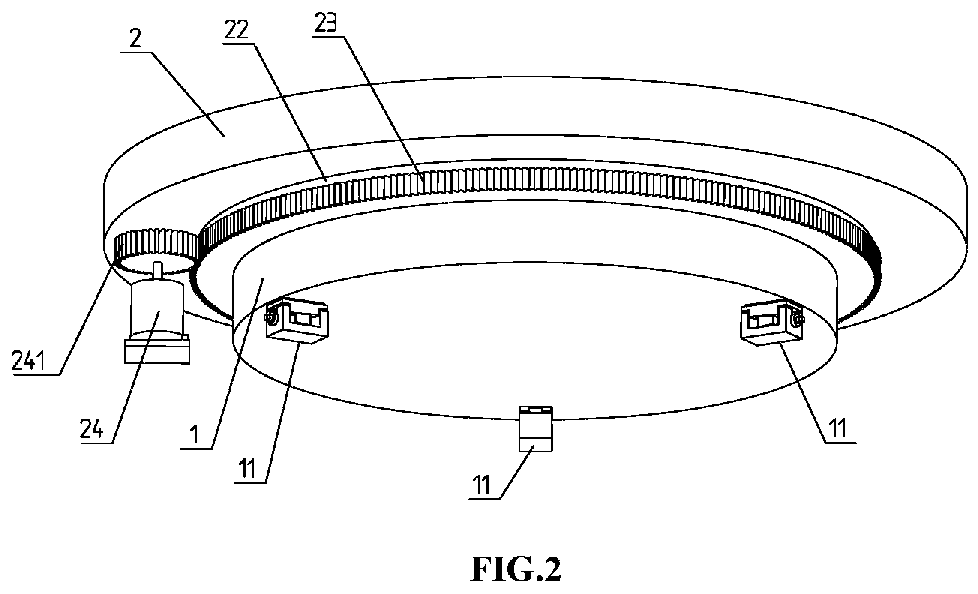
[0059] FIG. 2 is a perspective view of part of an intelligent continuous polishing machine as viewed upward.
[0060] FIG. 3 is a perspective view of the workpiece holding mechanism.
[0061] FIG. 4 is a perspective view of the lap measuring and cutting mechanisms.
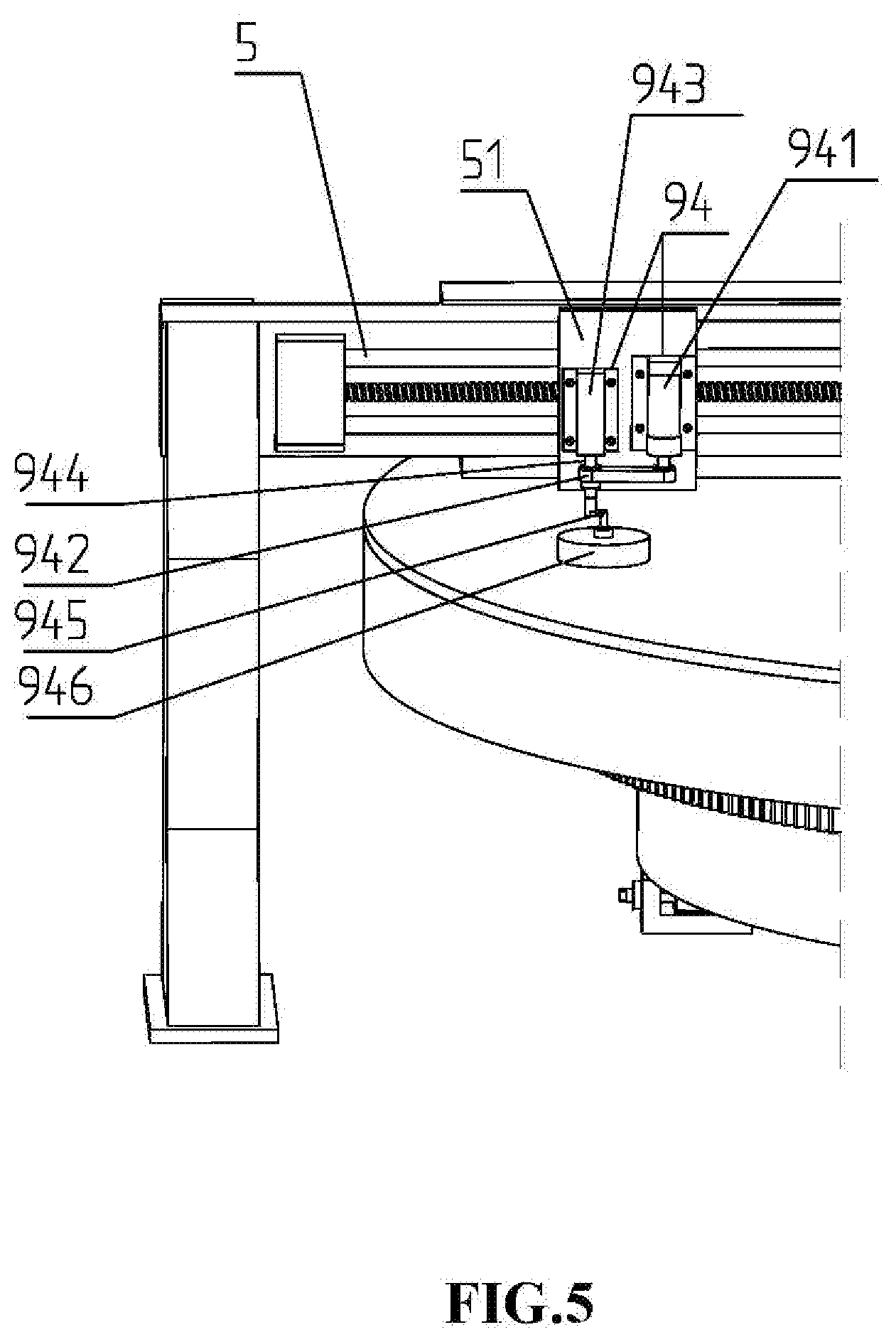
[0062] FIG. 5 is a perspective view of the small-conditioner holding mechanism.
[0063] FIG. 6 is a perspective view of the large-conditioner holding mechanism.
[0064] FIG. 7 is a diagram of configurations for determining the coupled error of the aerostatic slide guide.
[0065] FIG. 8 is a diagram of configurations for determining the absolute verticality error of the lap rotary axis.
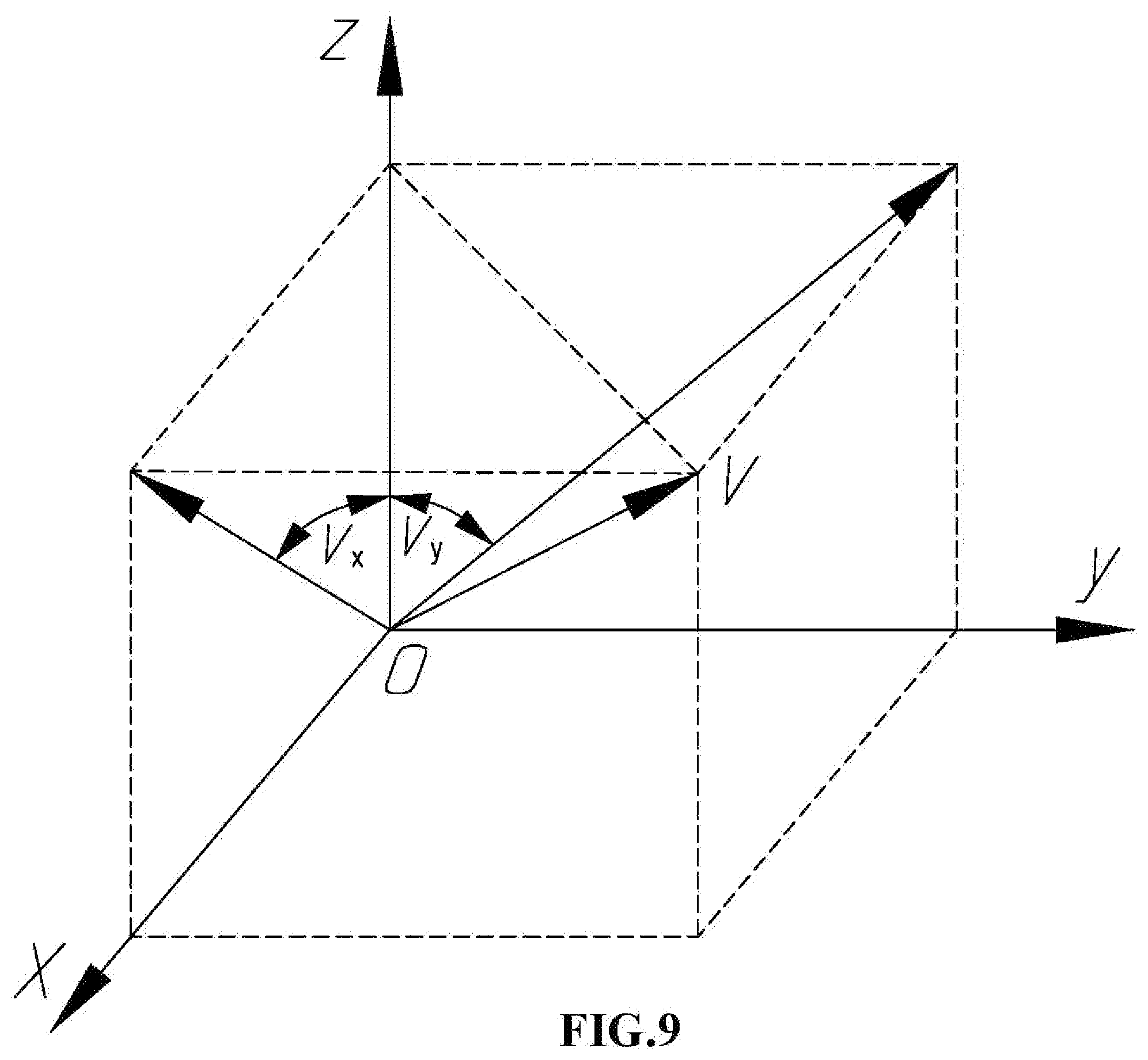
[0066] FIG. 9 is a diagram of the absolute verticality error of the lap rotary axis.
DETAILED DESCRIPTION OF THE DISCLOSURE
[0067] Referring to FIGS. 1 and 2, the intelligent continuous polishing machine 100 includes a rotary platen 2 mounted on a base platen 1. The base platen 1 is configured with a group of through holes for compressed air at the center area. Compressed air with a preset pressure is fed from the lower ports of the through holes and released from the upper ports to form a very thin cushion between the rotary platen 2 and base platen 1, so that the rotary platen 2 rides on the thin cushion of compressed air. The top surface of the base platen 1 and the bottom surface of the rotary platen 2 have a high precision surface shape so that the thin cushion of compressed air can be formed.
[0068] The base platen 1 is placed on three supporting blocks 11 that are mounted on ground. The supporting height of the three supporting blocks 11 can be adjusted respectively so as to control the absolute verticality error of the base platen 1 rotary axis.
[0069] A layer of polishing pitch is prepared on the top surface of the rotary platen 2 to form a polishing lap 21. The bottom side of the rotary platen 2 is processed into a lug section 22 that has a smaller diameter. A gear ring 23 is installed around the circumference of the lug section 22. A drive motor assembly 24 is fixed beside the lug section 22, and the drive gear 241 of the drive motor assembly 24 matches the gear ring 23 around the lug section 22 so as to rotate the rotary platen 2.
[0070] This unique design of air bearing and gear ring driving configuration has significant advantages. It virtually eliminates vibration at the polishing surface, and dramatically improves workpiece figure and finish results. In addition, the axial and radial runout error of the rotary platen 2 during operation is small which is required for the measuring the surface shape of the pitch lap 21.
[0071] Referring to Figs. ,1 and 2, the intelligent continuous polishing machine 100 includes a multi-beam bridge mechanism 3 installed above the rotary platen 2. The multi-beam bridge mechanism 3 is configured with four horizontal beams 31-34. A first linear slide guide 4 configured with a movable block 41 is installed on one side of the first horizontal beam 31, and a second linear slide guide 5 configured with a movable block 51 is installed on the other side. A third linear slide guide 7 configured with a movable block 71 is installed on, the third horizontal beam 33, and a fourth linear slide guide 8 configured with a movable block 81 is installed on the fourth horizontal beam 34.
[0072] A guide base 321 is installed on the second horizontal, beam 32 through an adjusting structure 322. A precision aerostatic slide guide 6 configured with a movable block 61 is fixed on the guide base 321. An electronic inclinometer 323 is mounted on the guide base 321 for determining the inclination of the guide base 321 and the aerostatic slide guide 6. The inclination of the guide base 321 and the aerostatic slide guide 6 can be regulated by the adjusting structure 322. The guide base 321 is made from thermo-stable materials such as granite assuring precision of the aerostatic slide guide 6. The movable block 61 can be controlled to move along the aerostatic slide guide 6.
[0073] Referring to FIG. 3, the intelligent continuous polishing machine 100 includes a first workpiece holding mechanism 90 installed on the movable block 41 of the first linear slide guide 4. The workpiece holding mechanism 90 comprises: a supporting frame 901, three holding wheels 902, a work ring 903, a septum 904 and a drive motor 905. The supporting frame 901 includes an upper part 906 fixed on the movable block 41 of the first linear slide guide 4 and a lower part 907 configured with an opening. The three holding wheels 903 are installed around the opening of the lower part 907, and the work ring 903 placed within the opening is held by the three holding wheels 902. A gear belt 908 is installed around the circumference of the work ring 903. The drive motor 905 is installed on the lower part 907 of the supporting frame 901, and the drive gear of the drive motor 905 matches the gear belt 908 of the work ring 902 so as to rotate the work ring 903. The septum 904 is fixed within the work ring 903, and the workpiece is placed within the septum 904 during polishing.
[0074] The intelligent continuous polishing machine 100 includes a second workpiece holding mechanism 91 installed on the movable block 81 of the fourth linear slide guide 8. The configuration of the second workpiece holding mechanism 91 is the same as the first workpiece holding mechanism 90.
[0075] This unique design of workpiece holding mechanism configurations has significant advantages. The work ring and the septum are not placed on the pitch lap, which avoid deteriorate the surface shape of the pitch lap.
[0076] Referring to FIG. 4, the intelligent continuous polishing machine includes a lap measuring mechanism 92 installed on the movable block 61 of the precision aerostatic slide guide 6. The lap measuring mechanism 92 includes a displacement sensor 921, a featured measuring tool 922 and a measuring object 923. The displacement sensor 921 is fixed on the movable block 61 through an adjustable connector 924. The measuring tool 922 includes an upper part fixed on the movable block 61 and a lower part with a work hole. The measuring object 923 is placed within the work hole.
[0077] The pitch lap 21 contains slurry channels that cause discontinuities on the surface. The measuring object 923 is used as a means to bridge small discontinuities on the lap surface and provide physical averaging for the lap surface. The measuring object 923 has a smooth surface that is in contact with the lap surface, and the dimensions of the smooth surface are larger than the maximum width of the channels. The measuring tool 922 is configured to constrain the measuring object 923 to move across the lap surface, and the displacement sensor 921 is configured to measure the position of the measurement object 923 that has a single degree of freedom in the vertical direction.
[0078] Referring to FIG. 4, the intelligent continuous polishing machine 100 includes a lap cutting mechanism 93 installed on the movable block 61 of the precision aerostatic slide guide 6. The lap cutting mechanism 93 comprises: a fifth linear slide guide 931 configured with a movable block 932, a high-speed motor 933 fixed on the movable block 932, and a cutting knife 934 installed on the rotor of the high-speed motor 933. The cutting knife 934 is driven by the high-speed motor 933 to rotate at a high speed so as to cut the lap surface. The movable block 932 is controlled to move along the fifth linear slide guide 931 in the vertical direction, so that the cutting depth of the cutting knife 934 into the lap surface can be controlled instantaneously as the cutting knife 934 moves along the lap surface radially.
[0079] Referring to FIG. 5, the intelligent continuous polishing machine 100 includes a small-conditioner holding mechanism 94 installed on the movable block 51 of the second linear slide guide 5. The small-conditioner holding mechanism 94 comprises: a drive motor 941, a drive belt 942, a pneumatic cylinder 943 configured with a piston rod 944, an eccentricity adjusting structure 945, and a small conditioning tool 946. The drive motor 941 rotates the piston rod 944 of the pneumatic cylinder 943 through the drive belt 942. The eccentricity adjusting structure 945 includes an upper column fixed on the piston rod 944 and a lower column connecting the small conditioning tool 946 by a ball joint structure. The eccentricity of the lower column with respect to the piston rod 944 can be adjusted by the eccentricity adjusting structure 945. The applying force of the small conditioning tool 946 onto the lap surface can be altered and controlled by the pneumatic cylinder 943 through the piston rod 944. The small-conditioner holding mechanism 94 is configured to rotate the small conditioning tool 946 with a determined eccentricity under a constant loading.
[0080] This unique design of the small-conditioner holding mechanism 94 has significant advantages. The small conditioning tool 946 rotating with an eccentricity is beneficial to generating a work function of desired profile, and the small conditioning tool 946 controlled by the pneumatic cylinder 943 under a determined pneumatic pressure is beneficial to keeping a stable work function. Further, the size and magnitude of the work function can be altered by adjusting the eccentricity of the small conditioning tool 946 and changing the pneumatic pressure of the pneumatic cylinder 943.
[0081] Referring to FIG. 6, the intelligent continuous polishing machine 100 includes a large-conditioner holding mechanism 95 installed on the movable block 71 of the third linear slide guide 7. The large-conditioner holding mechanism 95 comprises: a conditioner lifting structure 951, a large conditioner 952, and a drive motor 953.
[0082] The conditioner lifting structure 951 are fixed on one side of the movable block 71. The large conditioner 952 is connected to the conditioner lifting structure 951 while placed on the lap, and the loading force of the large conditioner 952 onto the lap can be controlled by the conditioner lifting structure 951. A gear belt 954 is installed around the circumference of the large conditioner 952. The drive motor 953 is fixed on the other side of the movable block 71, and the drive gear of the drive motor 953 matches the gear belt 954 of the large conditioner 952 so as to rotate the large conditioner 952. The large-conditioner holding mechanism 95 installed the movable block 71 can be controlled to move radially along the third linear slide guide 7.
[0083] Referring to FIG. 1, the intelligent continuous polishing machine 100 includes a control computer 200 that can control every subsystems of the machine 100, including: 1) accurate angular positioning and rotary speed of the rotary platen 2 and the pitch lap 21 through the drive motor assembly 24; 2) accurate radial positioning and rotary speed of the work ring 903 and the workpiece 10 through the first linear slide guide 4 and the drive motor 905; 3) accurate radial positioning and rotary speed of the large conditioner 952 through the third linear slide guide 7 and the drive motor 953; 4) accurate radial positioning and translation speed of the measuring tool 922 in the lap measuring mechanism through, the aerostatic slide guide 6; 5) accurate height positioning and rotary speed of the cutting knife 934 through the fifth linear slide guide 931 and the high-speed motor 933; 6) accurate radial positioning and translation speed of the small conditioning tool 946 through the second linear slide guide 5; 7) accurate pressure of the small conditioning tool 946 through the pneumatic cylinder 943.
[0084] Computer numerical controlled (CNC) programs can be used, with proper feedback from linear and rotary encoders, to allow these accurate positioning and speed controls.
[0085] An intelligent continuous polishing process includes a normal polishing procedure, a lap measuring procedure, and three procedures for correcting the lap surface shape error: a lap cutting procedure, a sub-aperture correcting procedure, and a full-aperture correcting procedure. All of these procedures are controlled by the control computer 200 through CNC programs.
[0086] The normal polishing procedure is conducted when polishing the workpiece. During the normal polishing procedure, the workpiece 100 to be polished is placed on the lap 21 in the septum 904 within the work ring 903. The computer 200 controls the rotation of the pitch lap 21, the rotation and translation of the work ring 903, and sometimes the rotation and translation of the large conditioner 952 if the full-aperture correction procedure is being conducted simultaneously. The abrasive slurry is fed onto the lap surface and transported to the polishing site by the slurry channels on the surface. Material is removed from the workpiece surface by the slurry particles, achieving a desired surface figure.
[0087] The surface figure of the workpiece primarily depends on the surface shape of the pitch lap 21. When the surface figure deteriorates and does not meet the required specifications, one can consider measuring and correcting the surface shape of the pitch lap 21.
[0088] The lap measuring procedure is conducted when measuring the surface shape of the pitch lap 21. The lap surface shape can be measured by moving the measurement point of the displacement sensor 921 in a generally radial direction while the rotary platen 2 rotates. The movement of the displacement sensor 921 can be achieved using the aerostatic slide guide 6 configured with the movable block 61. It generates a spiral path with a self-defined pitch and provides an opportunity to interrogate the entire lap surface efficiently and repeatedly. When the radial motion of the displacement sensor 921 and the rotary motion of the lap 21 are servo controlled or monitored using encoder feedback, the exact position on the lap surface for every measurement can be obtained with precision.
[0089] The reference for measuring the lap surface shape is the aerostatic slide guide 6. The aerostatic slide guide 6 is positioned almost perpendicular to the lap rotary axis, but it wouldn't be perfectly perpendicular. The slide perpendicularity error with respect to the lap rotary axis should be considered because it is interpreted as a tapered shape error in the lap 21. Furthermore, as the displacement sensor 921 fixed on the movable block 61 is servo motorized to translate along the aerostatic slide guide 6 while moving across the lap surface, the straightness error of the aerostatic slide guide 6 is also interpreted as the shape error in the lap. Thus, the reference error of the lap measuring procedure includes the slide perpendicularity error with respect to the lap rotary axis and the slide straightness error. The slide perpendicularity error with respect to the lap rotary axis can be decomposed into the absolute inclination error of the slide mechanism and the absolute verticality error of the lap rotary axis. The coupled error of the absolute inclination error and straightness error of the aerostatic slide guide 6 can be determined using the displacement configured as FIG. 7. The absolute verticality error of the lap rotary axis can be determined using an electronic inclinometer configured as FIG. 8.
[0090] Referring to FIG. 7, it is configured to determine the coupled error of the absolute inclination error and straightness error of the aerostatic slide guide 6. A tank 300 filled with water is placed under the aerostatic slide guide 6 on the lap 10. The displacement sensor 921 fixed on the movable block 61 of the aerostatic slide guide 6 is configured to measure the water surface as the movable block is servo motorized to translate along the aerostatic slide guide 6. As the water surface that is almost horizontal would not introduce external errors, the measured error is exactly the coupled error of the absolute inclination error and straightness error of the aerostatic slide guide 6.
[0091] Referring to FIG. 8, it is configured to determine the absolute verticality error of the lap rotary axis. An electronic inclinometer 25 is placed on a platen 26 that is mounted on the pitch lap 21, and the electronic inclinometer 25 is oriented to the lap center. The pitch lap 21 is servo motorized to, rotate at a constant rotary speed. The instantaneous inclination is recorded when the electronic inclinometer 25 passes through the aerostatic slide guide 6 as well as the opposing side, i.e., q.sub.1 and q.sub.2. Then, the absolute verticality error of the lap rotary axis can be attained, i.e., q=(q.sub.1-q.sub.2)/2.
[0092] Referring to FIG. 9, the absolute verticality error of the lap rotary axis could be oriented to any direction. However, it can be divided into two components. One is in a first vertical plane within the aerostatic slide guide 6 (YOZ plane), while the other is in a second vertical, plane perpendicular to the aerostatic slide guide 6 (XOZ plane). Only the component of the absolute verticality error in the first vertical plane, that can be determined with the process above, affects the measured surface shape of the pitch lap 21.
[0093] The absolute verticality error of the lap rotary axis can be improved. As the rotary platen 2 and base platen 1 are placed on the three supporting blocks 11 that are mounted on ground, the supporting height of the three supporting blocks 11 can be adjusted respectively so as to control the absolute verticality error of the lap rotary axis. Also, the absolute inclination error of the aerostatic guide 6 can be regulated using the adjustment structure 322. Then, the slide perpendicularity error with respect to the lap rotary axis can be eliminated.
[0094] In some implementations, measuring the surface shape of the pitch lap 21 involves the following steps: (a) determination of the coupled error of the aerostatic slide guide 6; (b) determination of the absolute verticality error of the lap rotary axis; (c) calculation of the reference error of the lap measuring procedure; (d) measurement of the surface shape of the pitch lap 21; (e) creation of the actual surface shape of the pitch lap 21 according to the reference error and the lap measuring data. An error map (e.g., surface shape error) of the pitch lap 21 is generated by comparing the actual surface shape with the desired surface shape. After the reference error of the lap measuring procedure and the error map of the pitch lap 21 are obtained, one can correct the surface shape error of the pitch lap 21 with one or some of the three correction procedures.
[0095] The lap cutting procedure is implemented by the lap cutting mechanism 93 under the control of the control computer 200. First, a radial profile of the desired surface that is radial symmetric is derived, and the moving profile of the cutting knife 934 can be obtained by integrating the radial profile of the desired surface and the reference error of the lap measuring procedure
[0096] During the lap cutting procedure, the pitch lap 21 is rotated by the drive motor assembly 24 at a determined low speed. The lap cutting mechanism 93 fixed on the movable block 61 of the aerostatic slide guide 6 is controlled to move along the pitch lap 21 radially, and the high-speed motor 933 fixed on the movable block 932 of the fifth slide guide 931 rotates the cutting knife 934 at a determined high speed to cut the pitch lap surface. The cutting height of the cutting knife 934 moving along the pitch lap 21 radially is controlled with the moving profile through the fifth slide guide 931 and the movable block 932, so as to compensate for the desired lap profile and the reference error. Thus a desired surface shape can be achieved for the pitch lap 21 in despite of the initial surface shape.
[0097] The sub-aperture correction procedure is implemented by the small-conditioner holding mechanism 94 under the control of the control computer 200. During the sub-aperture correction procedure, the small conditioning tool 946 is rotated by the drive motor 941 at a determined speed and is applied onto the lap surface by the pneumatic cylinder 943 at a determined loading pressure so as to achieve a stable work function. The eccentricity, rotary speed, and loading pressure of the small conditioning tool 946 can be varied to obtain work functions of different sizes and profiles. The work function of the small conditioning tool 946 can be obtained by measuring the surface shape of the pitch lap 21 before and after a determined working duration time. With the work function, the surface shape error of the pitch lap 21 can be corrected by controlling the dwell time of the small conditioning tool 946 over the lap surface. Then, the desired surface shape can be achieved. The positioning and dwell time of the small conditioning tool 946 over the lap surface can be implemented, by controlling the rotation of the pitch lap 21 and the radial motion of the small conditioning tool 946.
[0098] In some implementations, correcting the surface shape error of the pitch lap 21 by the sub-aperture correction procedure involves the following steps: (a) determination of the actual surface shape of the pitch lap 21; (b) calculation of the surface shape error, according to the actual surface shape and the desired surface shape; c) determination of the work function of the small conditioning tool 946; (d) calculation of the tool dwell time over the lap surface and the required motion; e) execution of the calculated conditioning program. These steps can be repeated continuously to achieve a desired surface shape of the pitch lap 21.
[0099] The full-aperture correction procedure is implemented by the large-conditioner holding mechanism 95 under the control of the control computer 200. During the full-aperture correction procedure, the large conditioner 952 is loaded on the pitch lap 21 with a radial eccentricity (e.g., the distance of the conditioner and lap centers), thus the pitch lap 21 made from viscoelastic polishing pitch would creep and the surface shape of the pitch lap 21 would changes.
[0100] The radial eccentricity of the large conditioner 952 has a significant effect on the surface shape of the pitch lap 21. When the radial eccentricity of the large conditioner 952 is increased, that is, the large conditioner 952 is moved outward, the contact pressure at the outer zone increases but that at the inner zone decreases. Thus, the surface shape of the pitch lap 21 becomes more convex or less concave, or vice versa. After the surface shape error of the pitch lap 21 is obtained, the adjustments of the radial eccentricity of the large conditioner 952 can be made to correct the surface shaper error. A convex surface shape error of the pitch lap 21 can be corrected by decreasing the radial eccentricity, while a concave surface shape error can be corrected by increasing the radial eccentricity. The full-aperture correction procedure can be conducted during the normal polishing process.
* * * * *
D00000
D00001
D00002
D00003
D00004
D00005
D00006
D00007
D00008
D00009
XML
uspto.report is an independent third-party trademark research tool that is not affiliated, endorsed, or sponsored by the United States Patent and Trademark Office (USPTO) or any other governmental organization. The information provided by uspto.report is based on publicly available data at the time of writing and is intended for informational purposes only.
While we strive to provide accurate and up-to-date information, we do not guarantee the accuracy, completeness, reliability, or suitability of the information displayed on this site. The use of this site is at your own risk. Any reliance you place on such information is therefore strictly at your own risk.
All official trademark data, including owner information, should be verified by visiting the official USPTO website at www.uspto.gov. This site is not intended to replace professional legal advice and should not be used as a substitute for consulting with a legal professional who is knowledgeable about trademark law.