Systems And Methods For Reaction And Transport Engineering Via Cellular Fluidics
DUDUKOVIC; Nikola ; et al.
U.S. patent application number 16/549543 was filed with the patent office on 2021-02-25 for systems and methods for reaction and transport engineering via cellular fluidics. The applicant listed for this patent is Lawrence Livermore National Security, LLC. Invention is credited to Sarah BAKER, Victor Alfred BECK, Swetha CHANDRASEKARAN, Joshua R. DEOTTE, Nikola DUDUKOVIC, Eric B. DUOSS, Jeremy Taylor FEASTER, Jennifer Marie KNIPE, Julie MANCINI, James OAKDALE, Fang QIAN, Marcus A. WORSLEY.
| Application Number | 20210053056 16/549543 |
| Document ID | / |
| Family ID | 1000004375997 |
| Filed Date | 2021-02-25 |


| United States Patent Application | 20210053056 |
| Kind Code | A1 |
| DUDUKOVIC; Nikola ; et al. | February 25, 2021 |
SYSTEMS AND METHODS FOR REACTION AND TRANSPORT ENGINEERING VIA CELLULAR FLUIDICS
Abstract
The present disclosure relates to a computer aided design (CAD) manufactured lattice structure. The structure may have a plurality of tessellated cells formed from a plurality of interconnected struts, with the interconnected struts formed from a curable resin. The interconnecting struts form voids within each cell, with the voids communicating with one another. The struts may be formed such that the voids have a non-uniform dimension to create a varying porosity within the lattice structure.
| Inventors: | DUDUKOVIC; Nikola; (Hayward, CA) ; BAKER; Sarah; (Dublin, CA) ; BECK; Victor Alfred; (Livermore, CA) ; CHANDRASEKARAN; Swetha; (Dublin, CA) ; DEOTTE; Joshua R.; (Livermore, CA) ; DUOSS; Eric B.; (Danville, CA) ; FEASTER; Jeremy Taylor; (Fremont, CA) ; KNIPE; Jennifer Marie; (Oakland, CA) ; MANCINI; Julie; (Livermore, CA) ; OAKDALE; James; (Castro Valley, CA) ; QIAN; Fang; (Santa Cruz, CA) ; WORSLEY; Marcus A.; (Hayward, CA) | ||||||||||
| Applicant: |
|
||||||||||
|---|---|---|---|---|---|---|---|---|---|---|---|
| Family ID: | 1000004375997 | ||||||||||
| Appl. No.: | 16/549543 | ||||||||||
| Filed: | August 23, 2019 |
| Current U.S. Class: | 1/1 |
| Current CPC Class: | B01L 2300/0893 20130101; B01L 2300/12 20130101; B01L 2400/0406 20130101; B01L 2300/0877 20130101; B01L 3/502707 20130101; B01L 2200/0678 20130101; B01L 2300/1805 20130101 |
| International Class: | B01L 3/00 20060101 B01L003/00 |
Goverment Interests
STATEMENT OF GOVERNMENT RIGHTS
[0001] The United States Government has rights in this invention pursuant to Contract No. DE-AC52-07NA27344 between the U.S. Department of Energy and Lawrence Livermore National Security, LLC, for the operation of Lawrence Livermore National Laboratory.
Claims
1. A computer aided design (CAD) manufactured lattice structure comprising: a plurality of tessellated cells formed from a plurality of interconnected struts, the interconnected struts formed from a curable resin; and the interconnecting struts forming voids within each cell, the voids communicating with one another, and the struts being formed such that the voids have a non-uniform dimension to create a varying porosity within the lattice structure.
2. The lattice structure of claim 1, wherein the interconnecting struts and the voids create at least one defined, capillary flow path within the lattice structure for a fluid entering the lattice structure.
3. The lattice structure of claim 1, wherein the lattice structure forms a single plane device having a porosity that creates a plurality of separate capillary flow paths for a fluid entering the a designated point of the lattice structure.
4. The lattice structure of claim 3, wherein the separate capillary flow paths are formed generally parallel to one another such that the fluid entering the designated point is split into the plurality of separate capillary flow paths after entering the lattice structure.
5. The lattice structure of claim 4, wherein the separate capillary flow paths form linear flow paths.
6. The lattice structure of claim 4, wherein the separate capillary flows are created in first and second non-parallel planes within the lattice structure.
7. The lattice structure of claim 2, wherein the capillary flow path forms a spiral flow path extending within an internal three dimensional volume of the lattice structure.
8. The lattice structure of claim 1, wherein the varying porosity is such as to create an increasing capillary flow action across a dimension of the lattice structure, from a first portion to a second portion of the lattice structure.
9. The lattice structure of claim 1, wherein at least a portion of the lattice structure is carbonized.
10. The lattice structure of claim 1, wherein the lattice structure forms a plurality of liquid-gas interfaces.
11. The lattice structure of claim 1, wherein the lattice structure is constructed using a catalyst to form a plurality of solid-liquid-gas interfaces.
12. The lattice structure of claim 1, wherein the lattice structure comprises a lattice fluidic device for evaporative mass transport, which is formed to create at least one of: the occurrence of liquid-gas interfaces throughout at least a portion of the lattice structure, the liquid-gas interfaces being are optimized for transport of species from the liquid phase to the gas phase; the occurrence of liquid-gas interfaces throughout at least a portion of the lattice structure, the liquid-gas interfaces being optimized for efficient dissolution of gas molecules into a liquid phase; or a lattice fluidic liquid-liquid extraction device, in which two liquids are brought into contact without mixing within the lattice structure, and a species of interest is transported by chemical potential driven diffusion from one phase to the other, at maximum occurrences of liquid-liquid interfaces within the lattice structure.
13. The lattice structure of claim 1, wherein the lattice structure comprises a lattice fluidic heat exchanger, which enables two immiscible fluids of different temperatures to be brought into contact within the lattice structure to facilitate heat transfer.
14. The lattice structure of claim 1, wherein the lattice structure forms a lattice fluidic thermal element, in which the lattice is made of a thermally conductive material and provides at least one of selective heating or cooling of the fluid.
15. A computer aided design (CAD) manufactured lattice structure comprising: a plurality of tessellated cells formed from a plurality of interconnected struts, the interconnected struts formed from a curable resin; the interconnecting struts forming voids within each cell, the struts being formed such that the voids have a non-uniform dimension and communicate with one another to create a varying porosity within the lattice structure; and wherein the lattice is constructed using a material which forms a catalyst to create solid-liquid-gas interfaces at each of the voids within the lattice structure.
16. The lattice structure of claim 15, wherein the plurality of tessellated cells form a three dimensional lattice structure.
17. The lattice structure of claim 16, wherein the plurality of tessellated cells enable a capillary flow through the structure to be controlled in two distinct planes non parallel to one another.
18. The lattice structure of claim 15, wherein the lattice structure creates a plurality of distinct capillary flow channels through the lattice structure, the flow channels residing in a common plane.
19. A method for forming an engineered lattice structure, the method comprising: using a substrate material to form a plurality of tessellated cells, the cells being defined in part by a plurality of interconnected struts; further forming the plurality of tessellated cells such that the interconnected struts define a plurality of voids in the plurality of tessellated cells, with the voids being in flow communication with one another; and further forming the plurality of tessellated cells such that at least a subplurality of the voids have different dimensions, to create a varying porosity within the lattice structure.
20. The method of claim 19, wherein the plurality of tessellated cells are further formed to create a plurality of flow paths within the lattice structure, and wherein different ones of the flow paths within the plurality of flow paths have different capillary flow characteristics.
Description
FIELD
[0002] The present disclosure relates generally to microfluidics, and more particularly to systems and methods for facilitating open cell lattices for engineering transport phenomena and chemical reactions, which provide desired flow properties.
BACKGROUND
[0003] The statements in this section merely provide background information related to the present disclosure and may not constitute prior art.
[0004] A growing area of importance in the field of microfluidics involves is obtaining even greater levels of control over chemical reactions at interfaces with a structure, as well as obtaining even greater control over heat and mass transport at interfaces within a structure. Obtaining greater levels of control at interfaces may be important for chemical reactions, as well as heat and mass transport, in various types of devices such as electrochemical devices, thermochemical devices, bio-reactor devices, batteries, fuel cells, etc., which often involve the application of micro-fluidics. Conventional microfluidics are typically limited to actively-pumped fluid transport in enclosed microchannels, and typically are limited to structures having in a planar configuration. More advanced microfluidic structures which enable degrees of control over chemical reactions, as well as heat and mass transfer, at interfaces within the structure, would potentially open up new possibilities in chemical/process engineering applications.
SUMMARY
[0005] This section provides a general summary of the disclosure, and is not a comprehensive disclosure of its full scope or all of its features.
[0006] In one aspect the present disclosure relates to a computer aided design (CAD) manufactured lattice structure. The structure may comprise a plurality of tessellated cells formed from a plurality of interconnected struts, with the interconnected struts formed from a curable resin. The interconnecting struts form voids within each cell. The voids communicate with one another, and the struts are formed such that the voids have a non-uniform dimension to create a varying porosity within the lattice structure.
[0007] In another aspect the present disclosure relates to a computer aided design (CAD) manufactured lattice structure. The structure may comprise a plurality of tessellated cells formed from a plurality of interconnected struts, with the interconnected struts formed from a curable resin. The interconnecting struts form voids within each cell, with the struts being formed such that the voids have a non-uniform dimension and communicate with one another to create a varying porosity within the lattice structure. The lattice structure is constructed using a material which forms a catalyst to create solid-liquid-gas interfaces at each of the voids within the lattice structure.
[0008] In still another aspect the present disclosure relates to a method for forming an engineered lattice structure. The method may comprise using a substrate material to form a plurality of tessellated cells, the cells being defined in part by a plurality of interconnected struts. The method may further include forming the plurality of tessellated cells such that the interconnected struts define a plurality of voids in the plurality of tessellated cells, with the voids being in flow communication with one another. The method may further include forming the plurality of tessellated cells such that at least a subplurality of the voids have different dimensions, to create a varying porosity within the lattice structure.
[0009] Further areas of applicability will become apparent from the description provided herein. It should be understood that the description and specific examples are intended for purposes of illustration only and are not intended to limit the scope of the present disclosure.
BRIEF DESCRIPTION OF THE DRAWINGS
[0010] The drawings described herein are for illustrative purposes only of selected embodiments and not all possible implementations, and are not intended to limit the scope of the present disclosure.
[0011] Corresponding reference numerals indicate corresponding parts throughout the several views of the drawings.
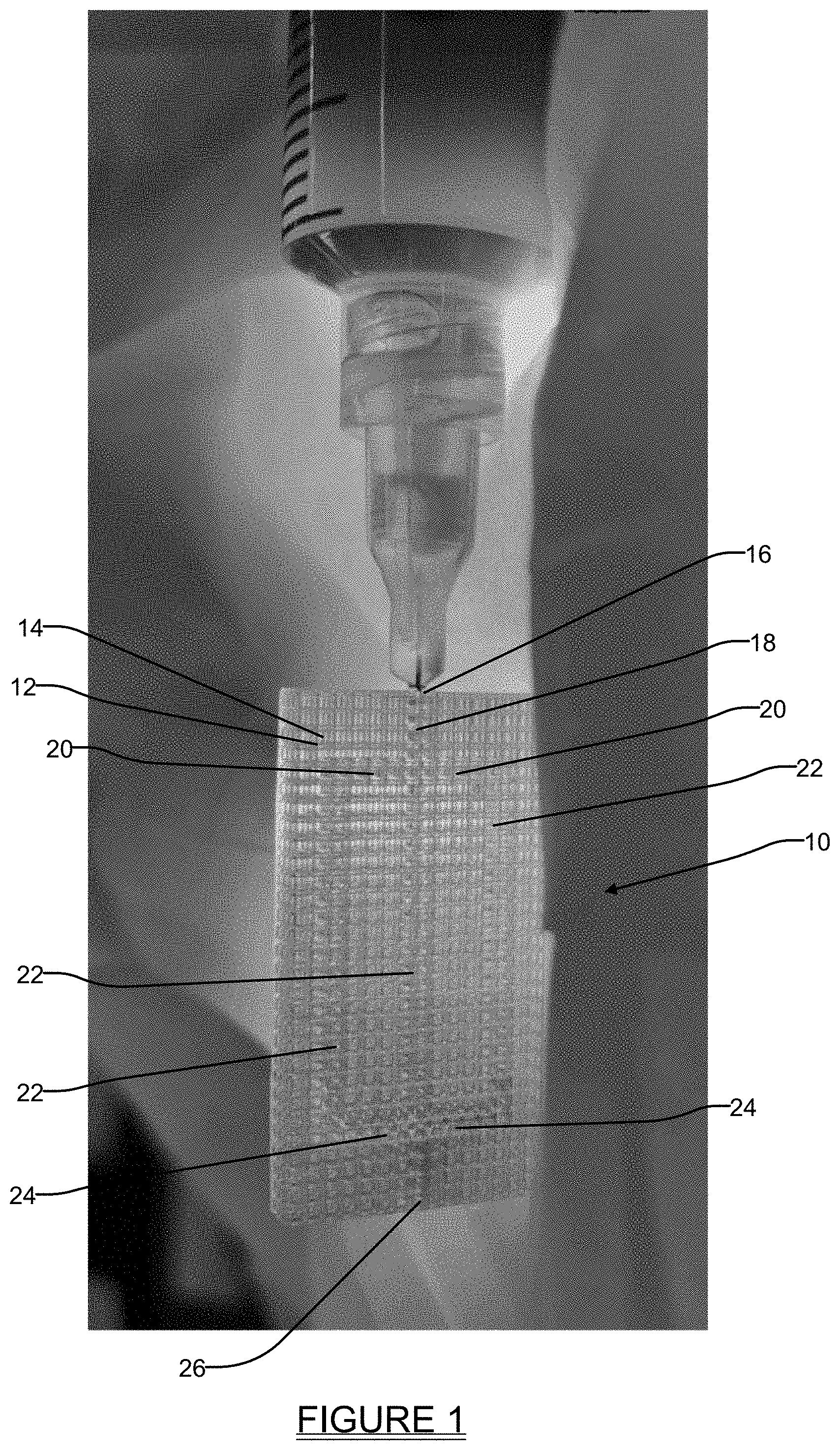
[0012] FIG. 1 is a perspective view of a single plane splitter lattice structure in accordance with one embodiment of the present disclosure;
[0013] FIG. 2 is a simplified diagrammatic representation of a 3D channel splitter lattice structure;
[0014] FIG. 3 is a an illustration of a plan (top) view of the 3D structure shown in FIG. 2, with fluid flowing through capillary action in two orthogonal planes into the lattice structure;
[0015] FIG. 4 is a side view of the lattice structure in FIG. 3 taken in accordance with section line 4-4 in FIG. 3 further illustrating the splitting of the capillary flow through the lattice structure;
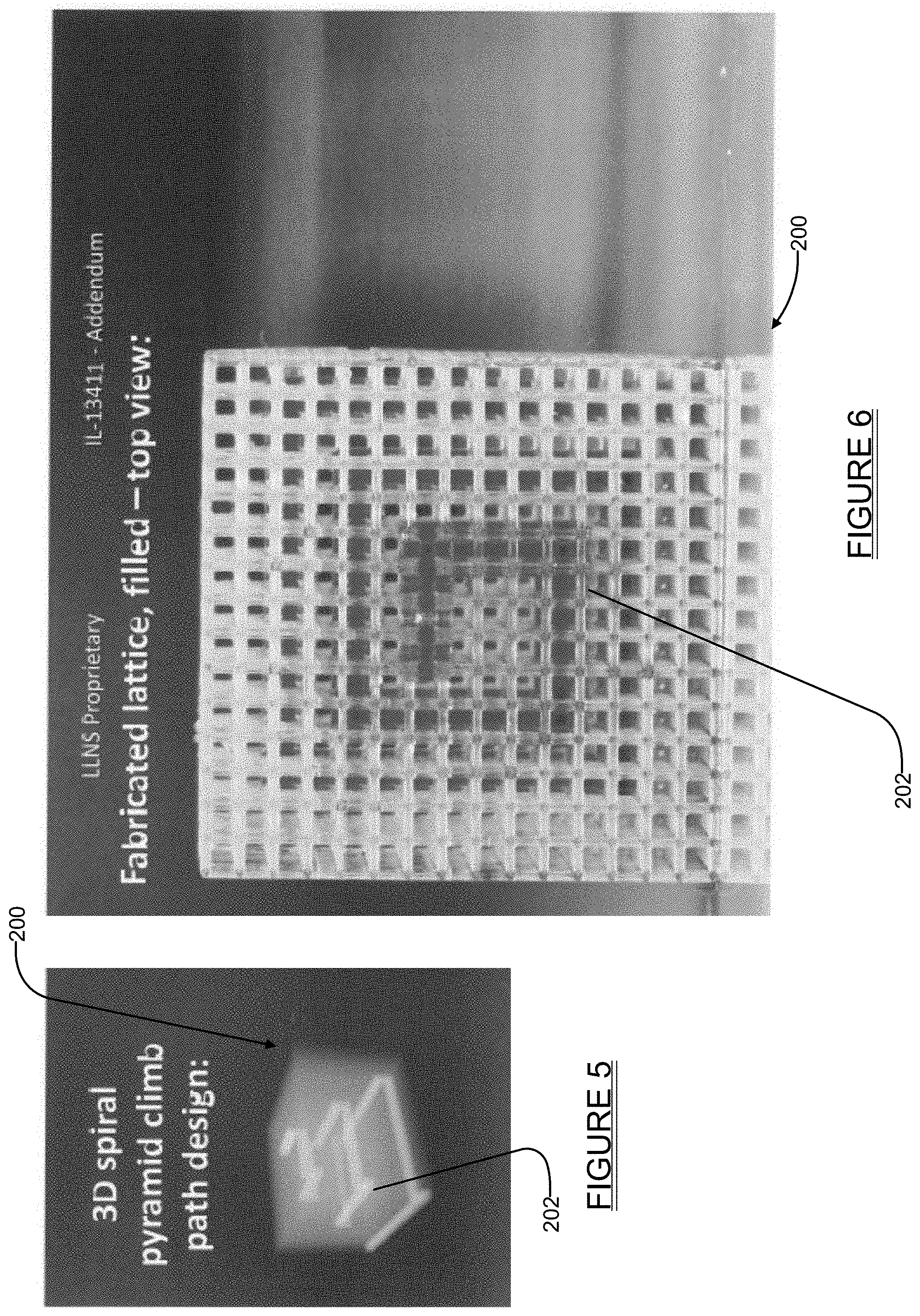
[0016] FIG. 5 is a perspective diagrammatic illustration of a 3D spiral flow pattern that may be created in a lattice structure using the teachings of the present disclosure;
[0017] FIG. 6 is a plan (top) view of a lattice structure in accordance with the present disclosure created to provide the 3D spiral flow pattern shown in FIG. 5;
[0018] FIG. 7a is a side view of a portion of a lattice structure in accordance with the present disclosure, illustrating how the size of the voids (i.e., pores) in each cell of the structure strongly influences the capillary flow characteristics within the structure;
[0019] FIG. 7b shows a side view of a portion of a lattice structure similar to that shown in FIG. 7a, but with the columns further spaced apart from one another, which limits bleed-through of fluid to adjacent columns; and
[0020] FIG. 8 shows various embodiments of different forms of lattice structures in accordance with the present disclosure, along with structures that have been carbonized to produce electrically conductive lattices.
DETAILED DESCRIPTION
[0021] Example embodiments will now be described more fully with reference to the accompanying drawings.
[0022] The present disclosure relates broadly to the design, fabrication and use of open cell lattices for facilitating engineering transport phenomena and chemical reactions. The architecture of the structures constructed using the teachings presented herein are "engineered" in the sense that the lattice structures are constructed in a highly defined manner in accordance with a CAD construction, and typically with a curable resin, to optimize important performance characteristics. Such performance characteristics may include control over porosity of the structure and capillary forces to provide desired flow properties including one or more desired capillary flow channels, as well as control over multi-phase interfaces and other functionalities that are important with microfluidic structures or devices.
[0023] The lattices of the present disclosure can be produced by additive manufacturing methods, for example and without limitation, via projection microstereolithography or two photon lithography. The use of additive manufacturing techniques to form the lattice structures of the various embodiments disclosed herein may be combined with other fabrication and processing techniques including, without limitation, fabrication techniques relating to surface functionalization, catalyst deposition, thermal treatment, removal of sacrificial material, etc. The foregoing manufacturing techniques may be used singly or in combination to achieve desired functionalities. Such desired functionalities may include one of, or combinations of, for example, a desired electric conductivity, a desired thermal conductivity, desired mechanical properties, a desired catalytic activity, or a desired stability, just to name a few important functionalities. By using lattice fluidics, a fluid can be distributed either passively (by capillary action alone) or actively (e.g., by pumping) in an open, three-dimensional configuration. These features offer significant potential for generating new microfluidic devices and related technologies in the field of chemical/process engineering and related devices (e.g., chemical/electrochemical reactors, packed beds, bubble columns, etc.).
[0024] FIG. 1 shows a lattice structure 10 in accordance with one embodiment of the present disclosure. The lattice structure 10 in this example forms a single plane channel splitter which is able to split a fluid flow into several desired paths within a single plane. The lattice structure 10 includes flow defining paths 12 and voids 14 having dimensions which, in this example, are engineered to provide the multi-flow path split seen occurring in the lattice structure 10. The fluid flow is injected or released at one end 16 of the lattice structure 10 and flows through capillary action along path 18 until branching into flows 20, which then propagate in three parallel paths 22 through a length of the lattice structure 10 before being channeled in flows 24 toward a center of the structure, and then re-combined into a single flow channel 26. Accordingly, the various flow channels are all presented within a single plane in this example. The dimensions of the fluid defining paths 12 and the voids 14 are controlled to provide the capillary action that creates these flow paths. While three parallel flow paths 22 are shown, together with one re-combined flow channel 26, it will be appreciated that a greater or lesser number of the flow paths 22 could be created, along with more than one re-combined flow channel 26.
[0025] FIG. 2 shows a diagrammatic perspective view of a 3D lattice splitter structure 100 design where the fluid flow through the splitter structure occurs in two distinct planes 102 and 104 arranged orthogonal to one another (i.e., in a 3D space). FIG. 3 shows the 3D lattice splitter structure 100 from a plan (top) view, illustrating the intersecting orthogonal flow planes 102 and 104. FIG. 4 shows a side view taken in accordance with section line 4-4 in FIG. 3 showing the plane 102. The plane 102 can be seen to be formed by two parallel paths 102a and 102b.
[0026] While the lattice splitter structure 100 is shown with only two orthogonally arranged flow planes 102 and 104, it will be appreciated that a 3D lattice structure with more than two orthogonal flow planes could just as easily be formed. For example, a lattice structure with three distinct non-perpendicular flow planes angularly arranged at 120 degrees from another (from a plan view perspective) could be provided.
[0027] FIGS. 5 and 6 show yet another 3D lattice structure 200 in accordance with another embodiment of the present disclosure. In this example the lattice structure 200 is engineered to provide a spiral, pyramid flow path 202 as indicated in the simplified diagrammatic drawing of FIG. 5. FIG. 6 shows a plan view (top view looking down) onto the lattice structure 200 to further illustrate the spiral, pyramid flow path 202.
[0028] FIG. 7a shows a portion of a lattice structure 300 constructed in accordance with one embodiment of the present disclosure to illustrate how the manufacture of the lattice structure 300 controls the capillary flow through cells of the structure. The lattice structure 300 is designed by tessellating one or more types of 3D unit cells in space. In this example the lattice structure 300 includes pluralities of unit cells 302a-302h formed by interconnecting struts 306, which form voids 302a1-302h1 in each unit cell. Unit cells 302a are disposed adjacent one another to form one column, while unit cells 302b-302h are also disposed in a like manner to form a plurality of closely adjacently positioned columns. In this example the unit cells 302a each have centrally formed voids 302a1, while unit cells 10b-10h each have voids 302b1-302h1, respectively. The voids 302a1 can be seen to be the largest in cross sectional area. The voids 302b1 are smaller in cross sectional area than the voids 302a1, voids 302c1 are smaller than the voids 302b1, and so forth, with the voids 302h1 being the smallest. Note also that the spacing between adjacent columns of cells decreases from left to right across the lattice structure 300, such that the columns formed by the cells 302a and 302b are spaced farther apart than columns formed by the unit cells 302g and 302h. FIG. 7b shows a similar lattice structure 300' but with the columns 302a'-302g' spaced even further apart, which prevents "bleed through" of liquid between adjacent columns. Accordingly, the spacing of the columns of the structures 300 and 300' can also be used to help control the capillary flow of fluid through the lattice structures.
[0029] The porosity of the lattice structure 10 can further be controlled by changing one or more parameters, for example, changing the unit cell size of each unit cell 302a-302h shown in FIG. 7a in one or more of the X, Y and/or Z dimensions, or changing the material used to construct the one or more of the unit cells 302a-302h. Porosity can also be changed by changing dimensions of the struts 306 that are used to form the cells 302a-302g so as to change the dimensions of the voids 302a1-302h1. In this example it will be noted that the struts 306 used to form the column of cells 302a are considerably thinner than those used to form column of cells 302h. The voids 302a1-302h1 (i.e., the empty space) in each unit cell 302a-302h influences the capillary flow of the liquid front, and can remain constant or change shape throughout the lattice structure 300. Curve 308 indicates how the porosity of the lattice structure 300 increases as the pore size (dimensions of the voids 302a1-302h1) creases.
[0030] The lattice structure 300 may also contain one or more additional features such as solid walls and surfaces, or selectively located inlets and outlets for fluid flow to enable connecting to microfluidic pumps and other components or devices. The final design of the lattice structure 300, or any of the other embodiments discussed herein, may be generated as a CAD (computer aided design) file.
[0031] When the physical lattice 10, 100, 200 or 300 is fabricated from the CAD file, such fabrication may be accomplished, in one example, by additive manufacturing methods such as projection microstereolithography (PuSL) or two photon lithography (2PL), in which a light source is used to selectively polymerize a pattern onto a surface of a photosensitive resin. The process is repeated layer-by-layer for each digital slice of the CAD file (microns to tens of microns in thickness). The photosensitive resin may contain (but is not limited to) one of more of the following components: (1) one or more monomer or polymer species, typically those undergoing light-initiated free radical polymerization (e.g., acrylates, thiolenes), (2) a photoinitiator, (3) a photoabsorber, (4) stabilizers or inhibitors (e.g., 4-methoxyphenol), (5) salts or solid fillers (e.g., catalyst material, sacrificial material, pore formers, nanoparticles for improved mechanical properties), (6) solvents or diluents, (7) other additives (e.g., surfactants, thermal initiators, sintering aids, adhesion promoters, etc.). The fabrication process may also include multiple resins (e.g., a hydrophilic and a hydrophobic polymer) that are selectively cured, as well as a rinsing step between swapping resins, for example by delivering water or solvents to the printed body, or dipping the printed body into a bath.
[0032] The fabricated lattice 10/100/200/300 may be cleaned using chemical or physical methods, for example through the use of solvents or through sonication, and may be post-cured. Post-curing may be carried out, for example, by using a UV chamber or similar light source, or by thermal treatment, and further functionalized (e.g., UV/ozone and oxygen plasma treatment).
[0033] Referring to FIGS. 8, examples of lattice structures 400, 500 and 600 which have been carbonized to form carbonized lattice structures 400', 500' and 600', respectively. In practice, one will be able to carbonize virtually any structure in order to make it electrically conductive. However, there is a fair amount of shrinkage during the carbonization process, as evident from the illustrations shown in FIG. 8, so this is an important factor that needs to be taken into account when designing the structure and the sizes of the cells/pores. The carbonized lattice structures 400'-600' are carbonized by thermally treating an underlying lattice structure to reduce the structure to a carbon-based structure which then has conductivity as one of its functionalities. The carbonized lattice structure 400' can be seen to include a substantially larger central void 400a', while carbonized lattice structure 500' includes a plurality of smaller voids 500a'. Carbonized lattice structure 600' differs still further by including a base portion 602' with a plurality of spaced apart columns 604' that project outwardly from the base portion. A principal feature of the structures shown in FIG. 8 is that due to capillary forces, the liquid will be contained in the tiny pores of the lattices and not bleed out into the larger voids 400a' of 400', 500a' of 500' and the spaces between columns 604'.
[0034] One or more catalyst materials or functional coatings may also be applied to any of the lattice structures 10, 100, 200, 400-600 or 400'-600' by methods including, but not limited, to: (1) electroplating, for example using copper, gold or silver, (2) electroless plating, for example using nickel phosphide, copper, or gold, (3) atomic layer deposition, (4) chemical vapor deposition, and (5) liquid flow and evaporation, such as by flowing a solution containing a solvent through the lattice structure 100-400, followed by evaporation of the solvent.
[0035] Catalyst-coated lattice structures may also be deployed as active electrodes in electrochemical reactors or fuel cells. This use can include incorporation into standard H-cell reactor configurations, liquid-fed, vapor-fed, and liquid/vapor-fed flow cells, or as gas diffusion electrodes (GDEs). A typical use case is the electrochemical reduction of carbon dioxide (CO2) into useful products. One example of a possible GDE setup using a lattice fluidic device may involve: (1) a cathode consisting of a lattice coated with a metallic catalyst (e.g., copper), (2) a liquid electrolyte (e.g., a hydroxide or salt solution) contained or flowing through the smaller capillary pores of the lattice, (3) the reactant gas (CO2) flowing through larger pores in the lattice, (4) a counter electrode (e.g., a similar lattice of a "mirrored" structure), (5) an anion exchange membrane, and (6) other electrochemical cell elements (e.g., reference electrode, O-rings/gaskets, tubing, electrode connections to external instrumentation, etc.). The use of lattice structures 400-600 constructed with solid-liquid-gas interfaces (catalyst-electrolyte-CO2) are expected to have especially significant commercial interest and activity.
[0036] The use of the engineered lattice structures 10/100/200/300/400'/500'/600' thus provides the ability to optimize the lattice structure by maximizing the occurrence of these triple-phase interfaces. Lattice structures 100-600 further enable shifting the overall reactor design space from a planar to a three-dimensional configuration, thereby even further increasing productivity per unit volume.
[0037] Other example implementations/applications for the lattice structures 10-600 disclosed herein include (but are not limited to): 1) A lattice fluidic device for evaporative mass transport, in which the occurrence of liquid-gas interfaces is optimized for transport of species from the liquid to the gas phase; 2) a lattice fluidic device for CO2 or other gas capture, in which the occurrence of liquid-gas interfaces is optimized for efficient dissolution of the gas molecules into the liquid phase; 3) a lattice fluidic liquid-liquid extraction device, in which two liquids are brought into contact without mixing, and the species of interest is transported by chemical potential driven diffusion from one phase to the other, at maximum occurrences of liquid-liquid interfaces; 4) a lattice fluidic heat exchanger, in which two immiscible fluids of different temperatures are brought into contact within the lattice to facilitate heat transfer; 5) a lattice fluidic thermal element, in which the lattice is made of a thermally conductive material and provides heating or cooling of the fluid selectively and efficiently; or 6) as printheads for ink delivery.
[0038] The systems and methods disclosed herein are expected to find utility in a wide range of devices. Such devices may include devices in which chemical reactions, heat and mass transport at interfaces are important, such as electrochemical devices, thermochemical devices, bio-reactor devices, batteries, fuel cells, etc. Specific applications may include, but are not limited to, electrochemical reaction catalysis at gas-liquid-solid interfaces, liquid-liquid interface extraction, microfluidic heat transfer, sensing platforms, controlled evaporation devices, and selective coating technologies.
[0039] The foregoing description of the embodiments has been provided for purposes of illustration and description. It is not intended to be exhaustive or to limit the disclosure. Individual elements or features of a particular embodiment are generally not limited to that particular embodiment, but, where applicable, are interchangeable and can be used in a selected embodiment, even if not specifically shown or described. The same may also be varied in many ways. Such variations are not to be regarded as a departure from the disclosure, and all such modifications are intended to be included within the scope of the disclosure.
[0040] Example embodiments are provided so that this disclosure will be thorough, and will fully convey the scope to those who are skilled in the art. Numerous specific details are set forth such as examples of specific components, devices, and methods, to provide a thorough understanding of embodiments of the present disclosure. It will be apparent to those skilled in the art that specific details need not be employed, that example embodiments may be embodied in many different forms and that neither should be construed to limit the scope of the disclosure. In some example embodiments, well-known processes, well-known device structures, and well-known technologies are not described in detail.
[0041] The terminology used herein is for the purpose of describing particular example embodiments only and is not intended to be limiting. As used herein, the singular forms "a," "an," and "the" may be intended to include the plural forms as well, unless the context clearly indicates otherwise. The terms "comprises," "comprising," "including," and "having," are inclusive and therefore specify the presence of stated features, integers, steps, operations, elements, and/or components, but do not preclude the presence or addition of one or more other features, integers, steps, operations, elements, components, and/or groups thereof. The method steps, processes, and operations described herein are not to be construed as necessarily requiring their performance in the particular order discussed or illustrated, unless specifically identified as an order of performance. It is also to be understood that additional or alternative steps may be employed.
[0042] When an element or layer is referred to as being "on," "engaged to," "connected to," or "coupled to" another element or layer, it may be directly on, engaged, connected or coupled to the other element or layer, or intervening elements or layers may be present. In contrast, when an element is referred to as being "directly on," "directly engaged to," "directly connected to," or "directly coupled to" another element or layer, there may be no intervening elements or layers present. Other words used to describe the relationship between elements should be interpreted in a like fashion (e.g., "between" versus "directly between," "adjacent" versus "directly adjacent," etc.). As used herein, the term "and/or" includes any and all combinations of one or more of the associated listed items.
[0043] Although the terms first, second, third, etc. may be used herein to describe various elements, components, regions, layers and/or sections, these elements, components, regions, layers and/or sections should not be limited by these terms. These terms may be only used to distinguish one element, component, region, layer or section from another region, layer or section. Terms such as "first," "second," and other numerical terms when used herein do not imply a sequence or order unless clearly indicated by the context. Thus, a first element, component, region, layer or section discussed below could be termed a second element, component, region, layer or section without departing from the teachings of the example embodiments.
[0044] Spatially relative terms, such as "inner," "outer," "beneath," "below," "lower," "above," "upper," and the like, may be used herein for ease of description to describe one element or feature's relationship to another element(s) or feature(s) as illustrated in the figures. Spatially relative terms may be intended to encompass different orientations of the device in use or operation in addition to the orientation depicted in the figures. For example, if the device in the figures is turned over, elements described as "below" or "beneath" other elements or features would then be oriented "above" the other elements or features. Thus, the example term "below" can encompass both an orientation of above and below. The device may be otherwise oriented (rotated 90 degrees or at other orientations) and the spatially relative descriptors used herein interpreted accordingly.
* * * * *
D00000
D00001
D00002
D00003
D00004
D00005
D00006
XML
uspto.report is an independent third-party trademark research tool that is not affiliated, endorsed, or sponsored by the United States Patent and Trademark Office (USPTO) or any other governmental organization. The information provided by uspto.report is based on publicly available data at the time of writing and is intended for informational purposes only.
While we strive to provide accurate and up-to-date information, we do not guarantee the accuracy, completeness, reliability, or suitability of the information displayed on this site. The use of this site is at your own risk. Any reliance you place on such information is therefore strictly at your own risk.
All official trademark data, including owner information, should be verified by visiting the official USPTO website at www.uspto.gov. This site is not intended to replace professional legal advice and should not be used as a substitute for consulting with a legal professional who is knowledgeable about trademark law.