Improved Cartridge For Use In In-vitro Diagnostics And Method Of Use Thereof
HODKO; Dalibor ; et al.
U.S. patent application number 16/958520 was filed with the patent office on 2021-02-25 for improved cartridge for use in in-vitro diagnostics and method of use thereof. This patent application is currently assigned to ADOR DIAGNOSTICS S.R.L.. The applicant listed for this patent is ADOR DIAGNOSTICS S.R.L.. Invention is credited to Dalibor HODKO, Vladimir HURGIN, Asaf LIPSHITZ, Mario SCHMITT, Amit SCHNELL, Paul D. SWANSON, Ari TADMOR, Lutz WEBER, Eran ZAHAVI.
| Application Number | 20210053051 16/958520 |
| Document ID | / |
| Family ID | 1000005247700 |
| Filed Date | 2021-02-25 |


View All Diagrams
| United States Patent Application | 20210053051 |
| Kind Code | A1 |
| HODKO; Dalibor ; et al. | February 25, 2021 |
IMPROVED CARTRIDGE FOR USE IN IN-VITRO DIAGNOSTICS AND METHOD OF USE THEREOF
Abstract
A cartridge for use in in-vitro diagnostics, the cartridge including a cartridge housing, a cartridge element, disposed within the cartridge housing and defining a plurality of operational volumes, at least some of the plurality of operational volumes being mutually linearly aligned, a fluid solution transporter operative to transfer fluid solutions from at least one of the plurality of operational volumes to at least another of the plurality of operational volumes, the fluid solution transporter including a linearly displaceable transport element operative to sequentially communicate with interiors of the at least some of the plurality of operational volumes and a venter, including a linearly displaceable venting element, operative in coordination with the fluid solution transporter to vent at least one of the plurality of operational volumes.
| Inventors: | HODKO; Dalibor; (San Diego, CA) ; SWANSON; Paul D.; (Santee, CA) ; HURGIN; Vladimir; (Gan Yavne, IL) ; SCHMITT; Mario; (Karlsruhe, DE) ; WEBER; Lutz; (Muenchweiler, DE) ; LIPSHITZ; Asaf; (Modiin, IL) ; ZAHAVI; Eran; (Rehovot, IL) ; TADMOR; Ari; (Herzlia, IL) ; SCHNELL; Amit; (Kiryat Tivon, IL) | ||||||||||
| Applicant: |
|
||||||||||
|---|---|---|---|---|---|---|---|---|---|---|---|
| Assignee: | ADOR DIAGNOSTICS S.R.L. Rome IT |
||||||||||
| Family ID: | 1000005247700 | ||||||||||
| Appl. No.: | 16/958520 | ||||||||||
| Filed: | July 4, 2018 | ||||||||||
| PCT Filed: | July 4, 2018 | ||||||||||
| PCT NO: | PCT/IL18/50726 | ||||||||||
| 371 Date: | June 26, 2020 |
| Current U.S. Class: | 1/1 |
| Current CPC Class: | B01L 2200/0652 20130101; B01L 2300/0672 20130101; B01L 2300/044 20130101; B01L 2300/043 20130101; C12N 15/1013 20130101; B01L 3/50273 20130101; B01L 3/502753 20130101 |
| International Class: | B01L 3/00 20060101 B01L003/00; C12N 15/10 20060101 C12N015/10 |
Foreign Application Data
| Date | Code | Application Number |
|---|---|---|
| Dec 28, 2017 | IL | PCT/IL2017/051398 |
Claims
1. (canceled)
2. A cartridge for use in in-vitro diagnostics, the cartridge comprising: a cartridge housing; a cartridge element disposed within said cartridge housing and defining a plurality of operational volumes; a fluid solution transporter operative to transfer fluid solutions from at least one of said plurality of operational volumes to at least another of said plurality of operational volumes; and at least one septum which sealingly communicates with at least some of said plurality of operational volumes.
3. A cartridge for use in in-vitro diagnostics according to claim 2 and wherein said at least one septum includes a plurality of septa.
4. A cartridge for use in in-vitro diagnostics according to claim 2 and wherein said at least one septum is penetrable by a penetrating element.
5. A cartridge for use in in-vitro diagnostics according to claim 2 and wherein at least one of said plurality of operational volumes is configured such that the interior thereof may be in magnetic communication with at least one magnet located exteriorly thereof.
6. (canceled)
7. A cartridge for use in in-vitro diagnostics according to claim 2 and wherein said fluid solution transporter comprises: a linearly displaceable transport element operative to sequentially communicate with interiors of said at least some of said plurality of operational volumes; and a fluid flow driving assembly communicating with said linearly displaceable transport element.
8-9. (canceled)
10. A cartridge for use in in-vitro diagnostics according to claim 2 and wherein said cartridge housing comprises first and second outer housing portions which are hinged together and at least partially enclose said cartridge element.
11-12. (canceled)
13. A cartridge for use in in-vitro diagnostics according to claim 2 and wherein said plurality of operational volumes includes a multiplicity of operational volumes, at least some of which are configured to allow injection of fluid solutions thereinto.
14. A cartridge for use in in-vitro diagnostics according to claim 2 and also comprising a microfluidic PCR array mounted within said cartridge housing.
15. A cartridge for use in in-vitro diagnostics according to claim 14 and wherein at least one of said plurality of operational volumes defines an internal passageway to a port of said microfluidic PCR array.
16. A cartridge for use in in-vitro diagnostics according to claim 2 and also comprising a sensor array mounted within said cartridge housing.
17-20. (canceled)
21. A method for use in in-vitro diagnostics, the method comprising: providing a cartridge having a plurality of operational volumes, at least some of said plurality of operational volumes being mutually linearly aligned; transferring fluid solutions from at least one of said plurality of operational volumes to at least another of said plurality of operational volumes, said transferring fluid solutions including linearly displacing a transport element to sequentially communicate with interiors of said at least some of said plurality of operational volumes; and venting said at least one of said plurality of operational volumes.
22. A method for use in in-vitro diagnostics according to claim 21 and wherein said transferring also includes driving said fluid solutions through said transport element between ones of said plurality of operational volumes.
23. A method for use in in-vitro diagnostics according to claim 21 and wherein said transferring fluid solutions includes transferring fluid solutions containing cellular material to a microfluidic PCR array mounted within said cartridge.
24. A method for use in in-vitro diagnostics according to claim 23 and wherein said transferring fluid solutions also comprises transferring fluid solutions containing cellular material from said microfluidic PCR array to a sensor array associated with said cartridge.
25. A method for use in in-vitro diagnostics according to claim 21 and also comprising injecting material into some of said plurality of operational volumes prior to supplying cellular material thereto.
26. A method for use in in-vitro diagnostics according to claim 21 and wherein said transferring fluid solutions comprises: locating a cell membrane breakdown material in a first operational volume; locating an open end of a hollow needle into communication with said first operational volume; drawing at least a portion of said cell membrane breakdown material into said hollow needle; linearly displacing said open end of said hollow needle into communication with a second operational volume having a sample located therein; and repeatedly drawing said sample and at least some of said cell membrane breakdown material into said hollow needle and expelling said sample and said cell membrane breakdown material from said hollow needle into said second operational volume, thereby mixing said sample and said cell membrane breakdown material.
27. A method for use in in-vitro diagnostics according to claim 26 and wherein said transferring fluid solutions further comprises: linearly displacing said open end of said hollow needle into communication with a third operational volume containing a cell lysis solution and magnetic beads; drawing at least a portion of said cell lysis solution and magnetic beads into said hollow needle into engagement with said sample and said cell membrane breakdown material; and repeatedly drawing said sample, at least some of said cell membrane breakdown material, said cell lysis solution and magnetic beads into said hollow needle and expelling said sample, said at least some of said cell membrane breakdown material, said cell lysis solution and said magnetic beads, from said hollow needle into said third operational volume, thereby releasing nucleic acids from said sample and binding said nucleic acids to said magnetic beads.
28. A method for use in in-vitro diagnostics according to claim 27 and wherein said transferring fluid solutions further comprises: linearly displacing said open end of said hollow needle into communication with a fourth operational volume containing a wash buffer; drawing at least a portion of said wash buffer into said hollow needle into engagement with said magnetic beads together with said nucleic acids bound thereto; and repeatedly drawing said wash buffer and said magnetic beads, together with said nucleic acids bound thereto, into said hollow needle, thereby washing away cell debris and unbound nucleic acids from said magnetic beads.
29. A method for use in in-vitro diagnostics according to claim 28 and wherein said transferring fluid solutions further comprises: linearly displacing said open end of said hollow needle into communication with a fifth operational volume containing an elution buffer; drawing at least a portion of said elution buffer into said hollow needle into engagement with said magnetic beads, together with said nucleic acids bound thereto; and repeatedly drawing said elution buffer and said magnetic beads, together with said nucleic acids bound thereto, into said hollow needle, thereby disengaging said nucleic acids from said magnetic beads.
30. A method for use in in-vitro diagnostics according to claim 29 and wherein said transferring fluid solutions further comprises: linearly displacing said open end of said hollow needle into communication with a sixth operational volume having at least one magnet juxtaposed thereto; transferring said elution buffer and said magnetic beads, together with said nucleic acids disengaged therefrom, into said sixth operational volume, said at least one magnet attracting said magnetic beads; and drawing said elution buffer, together with said nucleic acids, into said hollow needle.
31-35. (canceled)
Description
REFERENCE TO RELATED APPLICATIONS
[0001] The following patent applications, the disclosures of which are hereby incorporated by reference, are believed to be related to the subject matter of the present application:
[0002] Israel Patent Application No. 249856, filed Dec. 29, 2016 and entitled AN ELECTROPHERETIC CHIP FOR ELECTROPHORETIC APPLICATIONS, and
[0003] Israel Patent Application No. 249857, filed Dec. 29, 2016 and entitled AN ELECTROPHERETIC CHIP FOR ELECTROPHORETIC APPLICATIONS.
[0004] The following patent application, the disclosure of which is hereby incorporated by reference and priority from which is hereby claimed, is also related to the subject matter of the present application:
[0005] PCT Patent Application PCT/IL2017/051398, filed Dec. 28, 2017 and entitled CARTRIDGE FOR USE IN IN-VITRO DIAGNOSTICS AND METHOD OF USE THEREOF.
FIELD OF THE INVENTION
[0006] The present invention relates to in-vitro diagnostics generally.
BACKGROUND OF THE INVENTION
[0007] Various apparatus and methods for in-vitro diagnostics are known in the art.
SUMMARY OF THE INVENTION
[0008] The present invention seeks to provide a cartridge and an improved method for in-vitro diagnostics.
[0009] There is thus provided in accordance with a preferred embodiment of the present invention a cartridge for use in in-vitro diagnostics, the cartridge including a cartridge housing, a cartridge element, disposed within the cartridge housing and defining a plurality of operational volumes, at least some of the plurality of operational volumes being mutually linearly aligned, a fluid solution transporter operative to transfer fluid solutions from at least one of the plurality of operational volumes to at least another of the plurality of operational volumes, the fluid solution transporter including a linearly displaceable transport element operative to sequentially communicate with interiors of the at least some of the plurality of operational volumes and a venter, including a linearly displaceable venting element, operative in coordination with the fluid solution transporter to vent at least one of the plurality of operational volumes.
[0010] There is also provided in accordance with another preferred embodiment of the present invention a cartridge for use in in-vitro diagnostics, the cartridge including a cartridge housing, a cartridge element disposed within the cartridge housing and defining a plurality of operational volumes, a fluid solution transporter operative to transfer fluid solutions from at least one of the plurality of operational volumes to at least another of the plurality of operational volumes and at least one septum which sealingly communicates with at least some of the plurality of operational volumes.
[0011] Preferably, the at least one septum includes a plurality of septa. Additionally or alternatively, the at least one septum is penetrable by a penetrating element.
[0012] There is further provided in accordance with yet another preferred embodiment of the present invention a cartridge for use in in-vitro diagnostics, the cartridge including a cartridge housing defining a plurality of operational volumes and a fluid solution transporter operative to transfer fluid solutions from at least one of the plurality of operational volumes to at least another of the plurality of operational volumes, at least one of the plurality of operational volumes being configured such that the interior thereof may be in magnetic communication with at least one magnet located exteriorly thereof.
[0013] In accordance with a preferred embodiment of the present invention the fluid solution transporter includes a linearly displaceable transport element operative to sequentially communicate with interiors of the at least some of the plurality of operational volumes. Additionally or alternatively, the fluid solution transporter includes a fluid flow driving assembly communicating with the linearly displaceable transport element.
[0014] Preferably, the linearly displaceable transport element includes a hollow needle. Additionally or alternatively, the cartridge for use in in-vitro diagnostics also includes a flexible tube interconnecting the fluid flow driving assembly with the linearly displaceable transport element.
[0015] In accordance with a preferred embodiment of the present invention the cartridge housing includes first and second outer housing portions which are hinged together and at least partially enclose the cartridge element.
[0016] Preferably, the venter includes a needle assembly, which cooperates with the plurality of operational volumes.
[0017] In accordance with a preferred embodiment of the present invention the cartridge for use in in-vitro diagnostics also includes a sample insertion subassembly communicating with at least one of the plurality of operational volumes. Additionally or alternatively, the plurality of operational volumes include a multiplicity of operational volumes, at least some of which are configured to allow injection of fluid solutions thereinto.
[0018] In accordance with a preferred embodiment of the present invention the cartridge for use in in-vitro diagnostics also includes a microfluidic PCR array mounted within the cartridge housing. Additionally, at least one of the plurality of operational volumes defines an internal passageway to a port of the microfluidic PCR array.
[0019] Preferably, the cartridge for use in in-vitro diagnostics also includes a sensor array mounted within the cartridge housing. Additionally, at least one of the plurality of operational volumes defines an internal passageway to a port of the sensor array. Additionally or alternatively, the sensor array communicates with at least one of the plurality of operational volumes operating as a waste collection volume.
[0020] In accordance with a preferred embodiment of the present invention the cartridge for use in in-vitro diagnostics also includes a first plurality of fluid solution transporter locations respectively communicating with at least some of the plurality of operational volumes. Additionally, the cartridge for use in in-vitro diagnostics also includes a second plurality of venting element locations respectively communicating with the at least some of the plurality of operational volumes.
[0021] There is yet further provided in accordance with a still another preferred embodiment of the present invention a method for use in in-vitro diagnostics, the method including providing a cartridge having a plurality of operational volumes, at least some of the plurality of operational volumes being mutually linearly aligned, transferring fluid solutions from at least one of the plurality of operational volumes to at least another of the plurality of operational volumes, the transferring fluid solutions including linearly displacing a transport element to sequentially communicate with interiors of the at least some of the plurality of operational volumes and venting the at least one of the plurality of operational volumes.
[0022] In accordance with a preferred embodiment of the present invention the transferring also includes driving the fluid solutions through the transport element between ones of the plurality of operational volumes.
[0023] Preferably, the transferring fluid solutions includes transferring fluid solutions containing cellular material to a microfluidic PCR array mounted within the cartridge. Additionally, the transferring fluid solutions also includes transferring fluid solutions containing cellular material from the microfluidic PCR array to a sensor array associated with the cartridge.
[0024] Preferably, the method also includes injecting material into some of the plurality of operational volumes prior to supplying cellular material thereto.
[0025] In accordance with a preferred embodiment of the present invention the transferring fluid solutions includes locating a cell membrane breakdown material in a first operational volume, locating an open end of a hollow needle into communication with the first operational volume, drawing at least a portion of the cell membrane breakdown material into the hollow needle, linearly displacing the open end of the hollow needle into communication with a second operational volume having a sample located therein and repeatedly drawing the sample and at least some of the cell membrane breakdown material into the hollow needle and expelling the sample and the cell membrane breakdown material from the hollow needle into the second operational volume, thereby mixing the sample and the cell membrane breakdown material.
[0026] Preferably, the transferring fluid solutions further includes linearly displacing the open end of the hollow needle into communication with a third operational volume containing a cell lysis solution and magnetic beads, drawing at least a portion of the cell lysis solution and magnetic beads into the hollow needle into engagement with the sample and the cell membrane breakdown material and repeatedly drawing the sample, at least some of the cell membrane breakdown material, the cell lysis solution and magnetic beads into the hollow needle and expelling the sample, the at least some of the cell membrane breakdown material, the cell lysis solution and the magnetic beads, from the hollow needle into the third operational volume, thereby releasing nucleic acids from the sample and binding the nucleic acids to the magnetic beads.
[0027] In accordance with a preferred embodiment of the present invention the transferring fluid solutions further includes linearly displacing the open end of the hollow needle into communication with a fourth operational volume containing a wash buffer, drawing at least a portion of the wash buffer into the hollow needle into engagement with the magnetic beads together with the nucleic acids bound thereto and repeatedly drawing the wash buffer and the magnetic beads, together with the nucleic acids bound thereto, into the hollow needle, thereby washing away cell debris and unbound nucleic acids from the magnetic beads.
[0028] In accordance with a preferred embodiment of the present invention the transferring fluid solutions further includes linearly displacing the open end of the hollow needle into communication with a fifth operational volume containing an elution buffer, drawing at least a portion of the elution buffer into the hollow needle into engagement with the magnetic beads, together with the nucleic acids bound thereto and repeatedly drawing the elution buffer and the magnetic beads, together with the nucleic acids bound thereto, into the hollow needle, thereby disengaging the nucleic acids from the magnetic beads.
[0029] Preferably, the transferring fluid solutions further includes linearly displacing the open end of the hollow needle into communication with a sixth operational volume having at least one magnet juxtaposed thereto, transferring the elution buffer and the magnetic beads, together with the nucleic acids disengaged therefrom, into the sixth operational volume, the at least one magnet attracting the magnetic beads and drawing the elution buffer, together with the nucleic acids, into the hollow needle.
[0030] In accordance with a preferred embodiment of the present invention the transferring fluid solutions further includes linearly displacing the open end of the hollow needle into communication with a seventh operational volume which communicates with a microfluidic PCR array, transferring the elution buffer and the nucleic acids into the microfluidic PCR array, the microfluidic PCR array generating amplified nucleic acids by amplifying the nucleic acids, drawing the amplified nucleic acids into the hollow needle, linearly displacing the open end of the hollow needle into communication with an eighth operational volume containing a dilution buffer, drawing the dilution buffer into the hollow needle, into engagement with the amplified nucleic acids and repeatedly drawing the dilution buffer and the amplified nucleic acids into the hollow needle, thereby generating diluted nucleic acids.
[0031] Preferably, the transferring fluid solutions further includes linearly displacing the open end of the hollow needle into communication with a ninth operational volume which communicates with a sensor array, transferring at least a first portion of the diluted nucleic acids into the sensor array, thereby washing the sensor array and thereafter transferring a second portion of the diluted nucleic acids into operative engagement with the sensor array.
[0032] Preferably, the transferring fluid solutions further includes linearly displacing the open end of the hollow needle into communication with a tenth operational volume which contains a concentrated discriminator, drawing the concentrated discriminator into the hollow needle, linearly displacing the open end of the hollow needle into communication with an eleventh operational volume which contains a discriminator buffer, drawing the discriminator buffer into the hollow needle, into engagement with the concentrated discriminator, repeatedly drawing the discriminator buffer and the concentrated discriminator into the hollow needle and expelling the discriminator buffer and the concentrated discriminator from the hollow needle into the eleventh operational volume, thereby generating a diluted discriminator, drawing the diluted discriminator into the hollow needle, linearly displacing the open end of the hollow needle into communication with the ninth operational volume which communicates with the sensor array and transferring the diluted discriminator into operative engagement with the sensor array.
[0033] In accordance with a preferred embodiment of the present invention the transferring fluid solutions further includes linearly displacing the open end of the hollow needle into communication with a twelfth operational volume which contains a reporter reconstitution buffer, drawing the reporter reconstitution buffer into the hollow needle, repeatedly drawing the reporter reconstitution buffer into the hollow needle and expelling the reporter reconstitution buffer from the hollow needle into the twelfth operational volume via a thirteenth operational volume containing a dried reporter, thereby generating a reconstituted reporter, drawing the reconstituted reporter into the hollow needle, linearly displacing the open end of the hollow needle into communication with the ninth operational volume which communicates with the sensor array and transferring the reconstituted reporter into operative engagement with the sensor array.
[0034] In accordance with a preferred embodiment of the present invention the transferring fluid solutions further includes linearly displacing the open end of the hollow needle into communication with a fourteenth operational volume which contains an array wash buffer, drawing the array wash buffer into the hollow needle, linearly displacing the open end of the hollow needle into communication with the ninth operational volume which communicates with the sensor array and transferring the array wash buffer into operative engagement with the sensor array.
BRIEF DESCRIPTION OF THE DRAWINGS
[0035] The present invention will be understood and appreciated more fully from the following detailed description in which:
[0036] FIGS. 1A-1H are simplified respective front, back, top, bottom, first side and second side planar views and front and rear perspective views of a cartridge constructed and operative in accordance with a preferred embodiment of the present invention;
[0037] FIG. 2 is a simplified pictorial illustration of the cartridge of FIG. 1 in an open orientation, prior to sealing thereof;
[0038] FIGS. 3A, 3B and 3C are simplified respective illustrations of a core assembly useful in the embodiment of FIG. 2, wherein FIG. 3A is a pictorial illustration of the core assembly, and FIGS. 3B and 3C are planar view illustrations of respective opposite sides of a base portion thereof;
[0039] FIGS. 4A-4H are simplified respective front, back, top, bottom, first side and second side planar views and front and rear perspective views of a functionally enhanced core assembly, which can be used in the cartridge of FIGS. 1A-2 with suitable modifications to the cartridge housing;
[0040] FIG. 5 is a simplified exploded view illustration of the core assembly of FIGS. 4A-4H;
[0041] FIG. 6A-6H are simplified respective front, back, top, bottom, first side and second side planar views and front and rear perspective views of a microfluidic base portion of the core assembly of FIG. 4A-5;
[0042] FIG. 7 is a simplified exploded view illustration of a top cover assembly forming part of the core assembly of FIGS. 4A-5;
[0043] FIGS. 8A-8H are simplified respective front, back, top, bottom, first side and second side planar views and front and rear perspective views of a main portion of the top cover assembly of FIG. 7, forming part of the core assembly of FIGS. 4A-5;
[0044] FIGS. 9A-9E are simplified respective front, back and top/bottom planar views and front and rear perspective views of a first overmolded septum of the top cover assembly of FIG. 7;
[0045] FIG. 10A-10H are simplified respective front, back, top, bottom, first side and second side planar views and front and rear perspective views of a second overmolded septum of the top cover assembly of FIG. 7;
[0046] FIGS. 11A-11F are simplified respective front, back, top/bottom and side planar views and front and rear perspective views of a sample port sealing closure of the top cover assembly of FIG. 7;
[0047] FIGS. 12A-12D are simplified illustrations showing four typical stages of insertion of a sample into operative engagement with the core assembly of FIGS. 4A-11F;
[0048] FIGS. 13A-13G are simplified illustrations of typical further steps in the operation of a cartridge such as that shown in FIGS. 1A-2 including the core assembly of FIGS. 4A-11F, wherein FIG. 13A shows an operational state corresponding to that of FIG. 12D, FIGS. 13A-130 show the microfluidic base portion of FIGS. 6A-6H, and FIGS. 13B-13G show operative engagement with chamber B1 thereof and with the sample receiving chamber thereof;
[0049] FIGS. 14A-14E are simplified illustrations of typical further steps in the operation of a cartridge such as that shown in FIGS. 1A-2 including the core assembly of FIGS. 4A-11F, wherein FIG. 14A shows an operational state subsequent to that of FIG. 13G, FIGS. 14A-14E showing the microfluidic base portion of FIGS. 6A-6H and operative engagement with chamber B2 thereof;
[0050] FIGS. 15A-15E are simplified illustrations of typical still further steps in the operation of a cartridge such as that shown in FIGS. 1A-2 including the core assembly of FIGS. 4A-11F, wherein FIG. 15A shows an operational state subsequent to that of FIG. 14E, FIGS. 15A-15E showing the microfluidic base portion of FIGS. 6A-6H and operative engagement with chamber B3 thereof;
[0051] FIGS. 16A-16E are simplified illustrations of typical yet further steps in the operation of a cartridge such as that shown in FIGS. 1A-2 including the core assembly of FIGS. 4A-11F, wherein FIG. 16A shows an operational state subsequent to that of FIG. 15E, FIGS. 16A-16E showing the microfluidic base portion of FIGS. 6A-6H and operative engagement with chamber B4 thereof;
[0052] FIGS. 17A-17E are simplified illustrations of typical yet further steps in the operation of a cartridge such as that shown in FIGS. 1A-2 including the core assembly of FIGS. 4A-11F, wherein FIG. 17A shows an operational state subsequent to that of FIG. 16E, FIGS. 17A-17E showing the microfluidic base portion of FIGS. 6A-6H and operative engagement with chamber B5 thereof;
[0053] FIGS. 18A-18D are simplified illustrations of typical yet further steps in the operation of a cartridge such as that shown in FIGS. 1A-2 including the core assembly of FIGS. 4A-11F, wherein FIG. 18A shows an operational state subsequent to that of FIG. 17E, FIGS. 18A-18D showing the microfluidic base portion of FIGS. 6A-6H and operative engagement with chamber B6 thereof;
[0054] FIGS. 19A-19D are simplified illustrations of typical yet further steps in the operation of a cartridge such as that shown in FIGS. 1A-2 including the core assembly of FIGS. 4A-11F, wherein FIG. 19A shows an operational state subsequent to that of FIG. 18D, FIGS. 19A-19D showing the microfluidic base portion of FIGS. 6A-6I and operative engagement with chamber A3 thereof;
[0055] FIGS. 20A-20D are simplified illustrations of typical yet further steps in the operation of a cartridge such as that shown in FIGS. 1A-2 including the core assembly of FIGS. 4A-11F, wherein FIG. 20A shows an operational state subsequent to that of FIG. 19D, FIGS. 20A-20D showing the microfluidic base portion of FIGS. 6A-6H and operative engagement with chamber B7 thereof;
[0056] FIGS. 21A-21E are simplified illustrations of typical yet further steps in the operation of a cartridge such as that shown in FIGS. 1A-2 including the core assembly of FIGS. 4A-11F, wherein FIG. 21A shows an operational state subsequent to that of FIG. 200.
[0057] FIGS. 21A-21E showing the microfluidic base portion of FIGS. 6A-6H and operative engagement with a PCR amplification subsystem thereof;
[0058] FIGS. 22A-22G are simplified illustrations of typical yet further steps in the operation of a cartridge such as that shown in FIGS. 1A-2 including the core assembly of FIGS. 4A-11F, wherein FIG. 22A shows an operational state subsequent to that of FIG. 21E, FIGS. 22A 22G showing the microfluidic base portion of FIGS. 6A 6H and operative engagement with chamber B8 thereof;
[0059] FIGS. 23A and 23B are simplified illustrations of typical yet further steps in the operation of a cartridge such as that shown in FIGS. 1A-2 including the core assembly of FIGS. 4A-11F, wherein FIG. 23A shows an operational state subsequent to that of FIG. 22G, FIGS. 23A and 23B showing the microfluidic base portion of FIGS. 6A-6H and operative engagement with chamber A4 thereof;
[0060] FIGS. 24A-24F are simplified illustrations of typical yet further steps in the operation of a cartridge such as that shown in FIGS. 1A-2 including the core assembly of FIGS. 4A-11F, wherein FIG. 24A shows an operational state subsequent to that of FIG. 23B.
[0061] FIGS. 24A-24F showing the microfluidic base portion of FIGS. 6A-6H and operative engagement with chamber B10 thereof and with a sensor array thereof;
[0062] FIGS. 25A and 25B are simplified illustrations of typical yet further steps in the operation of a cartridge such as that shown in FIGS. 1A-2 including the core assembly of FIGS. 4A-11F, wherein FIG. 25A shows an operational state subsequent to that of FIG. 24F, FIGS. 25A and 25B showing the microfluidic base portion of FIGS. 6A-6H and operative engagement with chamber A5 thereof;
[0063] FIGS. 26A-26F are simplified illustrations of typical yet further steps in the operation of a cartridge such as that shown in FIGS. 1A-2 including the core assembly of FIGS. 4A-11F, wherein FIG. 26A shows an operational state subsequent to that of FIG. 25B.
[0064] FIGS. 26A-26F showing the microfluidic base portion of FIGS. 6A-6H and operative engagement with chamber B10 thereof and with a sensor array thereof;
[0065] FIGS. 27A and 27B are simplified illustrations of typical yet further steps in the operation of a cartridge such as that shown in FIGS. 1A 2 including the core assembly of FIGS. 4A-11F, wherein FIG. 27A shows an operational state subsequent to that of FIG. 26F, FIGS. 27A and 27B showing the microfluidic base portion of FIGS. 6A-6H and operative engagement with chamber A6 thereof;
[0066] FIGS. 28A-28F are simplified illustrations of typical yet further steps in the operation of a cartridge such as that shown in FIGS. 1A-2 including the core assembly of FIGS. 4A-11F, wherein FIG. 28A shows an operational state subsequent to that of FIG. 27B, FIGS. 28A-28F showing the microfluidic base portion of FIGS. 6A-6H and operative engagement with chamber B10 thereof and with a sensor array thereof;
[0067] FIGS. 29A and 29B are simplified illustrations of typical yet further steps in the operation of a cartridge such as that shown in FIGS. 1A-2 including the core assembly of FIGS. 4A-11F, wherein FIG. 29A shows an operational state subsequent to that of FIG. 28F, FIGS. 29A and 29B showing the microfluidic base portion of FIGS. 6A-6H and operative engagement with chamber A7 thereof;
[0068] FIGS. 30A-30F are simplified illustrations of typical yet further steps in the operation of a cartridge such as that shown in FIGS. 1A-2 including the core assembly of FIGS. 4A-11F, wherein FIG. 30A shows an operational state subsequent to that of FIG. 29B, FIGS. 30A-30F showing the microfluidic base portion of FIGS. 6A-6H and operative engagement with chamber B10 thereof and with a sensor army thereof;
[0069] FIGS. 31A-31F are simplified illustrations of typical yet further steps in the operation of a cartridge such as that shown in FIGS. 1A-2 including the core assembly of FIGS. 4A-11F, wherein FIG. 31A shows an operational state subsequent to that of FIG. 30F, FIGS. 31A-31F showing the microfluidic base portion of FIGS. 6A-6H and operative engagement with chamber B9 thereof and with a sensor array thereof; and
[0070] FIGS. 32A-32D are simplified illustrations of typical yet further steps in the operation of a cartridge such as that shown in FIGS. 1A-2 including the core assembly of FIGS. 4A-11F, wherein FIG. 32A shows an operational state subsequent to that of FIG. 31F, FIGS. 32A-32D showing the microfluidic base portion of FIGS. 6A-6H and operative engagement with chamber B13 thereof and with a sensor array thereof.
DETAILED DESCRIPTION OF A PREFERRED EMBODIMENT
[0071] Reference is now made to FIGS. 1A-1H, which are simplified respective front, back, top, bottom, first side and second side planar views and front and rear perspective views of a cartridge constructed and operative in accordance with a preferred embodiment of the present invention and to FIG. 2, which is a simplified pictorial illustration of the cartridge of FIG. 1 in an open orientation, prior to sealing thereof.
[0072] As seen in FIGS. 1A-1H and 2, there is provided a cartridge 100 having first and second planar portions 102 and 104, which are preferably hinged together by an integrally formed hinge 106.
[0073] First planar portion 102, an outer surface 108 of which is seen particularly in FIGS. 1A and 1G, preferably is a generally flat, generally rectangular element and includes first, second and third cut outs, respectively designated by reference numerals 112, 114 and 116, on a top edge 118 thereof, which cooperate with similarly spaced cut outs on second planar portion 104, which are described hereinbelow, to respectively define sample transport needle, venting needle and syringe piston access locations, as described hereinbelow. First planar portion 102 also may include a side cut out 120, for retaining a syringe flange.
[0074] First planar portion 102 also preferably defines a heater engagement aperture 124, a plurality of frangible seal plunger access apertures 126 and a magnet engagement aperture 128. Frangible seal plunger access apertures 126 are preferably implemented in accordance with the teachings of WO2012019599, entitled `Device for Transporting Small Volumes of a Fluid, in particular a Micropump or Microvalve`, the description of which is hereby incorporated by reference.
[0075] Second planar portion 104, an outer surface 130 of which is seen particularly in FIGS. 1B and 1H, preferably is a generally flat, generally rectangular element and includes a cut out 136 which defines, together with cut out 116, the syringe piston access location, as described hereinbelow. Second planar portion 104 also preferably includes a sample cover snap fit accommodating cut out 138. Second planar portion 104 also may include a side cut out 140, for retaining the syringe flange.
[0076] Second planar portion 104 also preferably defines a heater engagement aperture 144, a plurality of frangible seal plunger access apertures 146, a plurality of support protrusions 148 and a generally rectangular carbon array access aperture 150. Frangible seal plunger access apertures 146 are preferably implemented in accordance with the teachings of WO2012019599, entitled `Device for Transporting Small Volumes of a Fluid, in particular a Micropump or Microvalve`, the description of which is hereby incorporated by reference.
[0077] Second planar portion 104 preferably also includes first and second notches. 152 and 154, formed within an upper rim 156 thereof, seen most clearly in FIG. 1C. First and second notches 152 and 154 respectively define, together with first and second cut outs 112 and 114, sample transport needle and venting needle access locations.
[0078] Turning now to FIG. 2, it is seen that an inner surface 158 of first planar portion 102 preferably defines a first linear array 160 of venting needle slidable mounting protrusions 162 for engaging a linearly displaceable venting element, preferably embodied as a venting needle 164, during shipping and prior to use. It is also seen that inner surface 158 includes a second linear array 170 of sample transport needle slidable mounting protrusions 172 for engaging a linearly displaceable transport element, preferably embodied as a sample transport needle 174, during shipping and prior to use. It is appreciated that respective venting needle 164 and sample transport needle 174 are formed with respective needle griping base portions 176 and 178 and tubing connectors 180 and 182.
[0079] A sample transport tube 190 is connected to sample transport needle tubing connector 182 and preferably communicates with a luer connector 192 of a syringe 194, which is retained in position by a linear array 196 of syringe supports 198.
[0080] It is also seen that an inner surface 208 of second planar portion 104 preferably defines a linear array 216 of syringe supports 218, which cooperate with syringe supports 198 to retain syringe 194 in position. A core assembly 220 is retained within the housing preferably at least by first and second linear protrusions 222 and 224.
[0081] It is appreciated that the housing is closed subsequent to manufacture as by relative rotation of the first and second planar portions 102 and 104 about hinge 106.
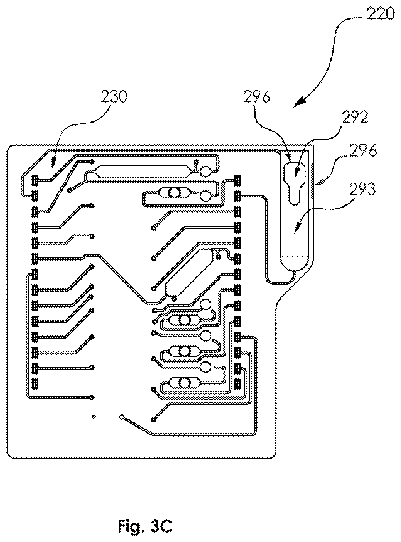
[0082] Reference is now made to FIGS. 3A, 3B and 3C, which are simplified respective illustrations of core assembly 220 useful in the embodiment of FIG. 2, wherein FIG. 3A is a pictorial illustration of the core assembly 220, and FIGS. 3B and 3C are planar view illustrations of a base portion thereof.
[0083] As seen in FIGS. 3A-3C, core assembly 220 preferably includes a base portion 230, which is illustrated in FIGS. 3B & 3C, a top cover assembly 240 having first and second septa 242 and 244 overmolded therewith as well as a first array of reagent filing ports 246 and a second array of reagent venting ports 248, which are employed during manufacture. Top cover assembly 240 is also provided with a plurality of alignment apertures 250 for receiving a corresponding plurality of alignment protrusions 252 on base portion 230, and a plurality of apertures 260 for accommodating reagent plugs 270 which are mounted onto base portion 230 and are preferably implemented in accordance with the teachings of EP2821138, entitled `Flow Cell with Integrated Dry Substance`, the description of which is hereby incorporated by reference`. Top cover assembly 240 is preferably also provided with a plurality of frangible seal plunger access apertures 276, preferably implemented in accordance with the teachings of WO2012019599 entitled `Device for Transporting Small Volumes of a Fluid, in particular a Micropump or Microvalve` and WO2016000998, entitled `Flow Cell comprising a Storage Zone and a Duct that can be Opened at a Predetermined Breaking Point`, the description of which is hereby incorporated by reference.
[0084] Top cover assembly 240 preferably also includes a flexible sample insertion port sealing cover 280, which removably and replaceably covers a sample insertion port 292 of a sample receiving chamber 293 defined by base portion 230. Flexible sample insertion port scaling cover 280 is preferably formed with a snap fit protrusion 294, which engages a corresponding recess 296 formed in the base portion 230. It is noted that core assembly 220 is particularly suitable for use in conducting RCA assays.
[0085] Reference is now made to FIGS. 4A-4H, which are simplified respective front, back, top, bottom, first side and second side planar views and front and rear perspective views of a functionally enhanced core assembly 400, useful for both RCA and PCR assays and which can be used in the cartridge of FIGS. 1A-2 with suitable dimensional modifications to the cartridge housing, and to FIG. 5, which is a simplified exploded view illustration of the core assembly of FIGS. 4A-4H.
[0086] As seen in FIGS. 4A-5, core assembly 400 constitutes a cartridge element preferably including a microfluidic base portion 410, a cover assembly 420, sealingly engaging the microfluidic base portion 410 on a first side thereof, a sealing cover film 430, sealingly engaging the microfluidic base portion 410 on a second side thereof, a carbon array 440 including a layer of double sided adhesive and which is mounted by means of the double side adhesive layer onto the sealing cover film 430, and a transparent carbon array cover 450.
[0087] As seen in FIG. 5, carbon array 440 includes a carbon array inlet aperture 460 and a carbon array outlet aperture 462. Additionally, sealing cover film 430 includes a carbon array inlet access aperture 470 and a carbon array outlet access aperture 472, which carbon array inlet access aperture 470 and a carbon array outlet access aperture 472 are respectively aligned with carbon array inlet aperture 460 and carbon array outlet aperture 462, when core assembly 400 is assembled.
[0088] Reference is now made additionally to FIG. 6A-6H, which are simplified respective front, back, top, bottom, first side and second side planar views and front and mar perspective views of microfluidic base portion 410 of the core assembly of FIG. 4A-5.
[0089] As seen in FIGS. 6A-6H, the microfluidic base portion 410 is a generally planar element preferably injection molded from polypropylene. A first surface 500 is seen in FIGS. 6A and 6G and a second, opposite surface 510 is seen in FIGS. 6B and 6H. The microfluidic base portion 410 is preferably formed with an array 520 of frangible seal access apertures 522, preferably implemented in accordance with the teachings of WO2012019599A2, entitled `Device for Transporting Small Volumes of a Fluid, in particular a Micropump or Microvalve`, the description of which is hereby incorporated by reference.
[0090] Turning initially principally to FIGS. 6A and 6G, which illustrate first surface 500, it is seen that there is provided an array 530 of venting needle guiding protrusions 532 arranged along a longitudinal axis 534. Each of guiding protrusions 532 defines a tunnel 536 and all of the tunnels are longitudinally aligned along axis 534.
[0091] Alongside array 530 is a generally longitudinal array 538 of reagent venting ports 540. Alongside array 538 is a reagent storage chamber defining protrusion 550, which preferably defines a plurality of reagent storage operational volumes or chambers 552, which are labeled for clarity in FIG. 6A as chambers B1-B14. Each of the reagent storage chambers is preferably provided with a throughgoing venting aperture 554 and a throughgoing reagent transport aperture 556.
[0092] Alongside reagent storage chamber defining protrusion 550 is a generally longitudinal array 560 of reagent supply ports 562.
[0093] Alongside reagent storage chamber defining protrusion 550 is a generally longitudinal array 570 of reagent plug receiving ports 572, preferably implemented in accordance with the teachings of EP2821138, entitled `Flow Cell with Integrated Dry Substance`, the description of which is hereby incorporated by reference.
[0094] Adjacent array 520 of frangible seal access apertures 522 is an array 580 of transport needle guiding protrusions 582 arranged along a longitudinal axis 584, which is preferably parallel to axis 534. Each of guiding protrusions 582 defines a tunnel 586 and all of the tunnels are longitudinally aligned along axis 584.
[0095] Adjacent array 580 is a microfluidic PCR array amplification subsystem 600 including a gas spring accommodating protrusion 602, preferably implemented in accordance with the teachings of WO2010139295, entitled `Apparatus for Transporting a Fluid within a Channel Leg of a Microfluidic Element` the description of which is hereby incorporated by reference, a plurality of PCR reagent plug receiving ports 604 and a recess 606 which defines a heater engagement region. Below PCR amplification subsystem 600 there is provided a sample receiving chamber 610 having a sample insertion aperture 612.
[0096] Turning now to FIGS. 6B and 6H, which illustrate second surface 510, it is seen that there is provided an array 630 of recesses 632, each of which recesses 632 communicates with a corresponding tunnel 536 of a corresponding venting needle guiding protrusion 532 arranged along longitudinal axis 534. Recesses 632 in combination with tunnels 536 preferably define a plurality of venting needle tip locations, which are labeled for clarity in FIG. 6H as venting needle tip locations V11-V23. Some of recesses 632 each communicate with a respective microfluidic channel 634, which in turn communicates with a venting aperture 554 of a corresponding one of chambers B1-14. Others of recesses 632 each communicate with a respective microfluidic channel 636, which in turn communicates with a corresponding one of reagent storage chambers 640, which am respectively labeled in FIG. 6B as chambers A1-A7. A further recess 632 communicates with the interior of sample receiving chamber 610 for providing venting thereof. One or more additional recess 632 coupled to a corresponding tunnel may be provided to enable additional functionality not currently contemplated.
[0097] It is also seen that there is provided an array 730 of recesses 732, each of which communicates with a corresponding tunnel 586 of a corresponding transport needle guiding protrusion 582 arranged along a longitudinal axis 584. Recesses 732 in combination with tunnels 586 preferably define a plurality of sample transport needle tip locations, which are labeled for clarity in FIG. 6H as sample transport needle tip locations T1-T23. Some of recesses 732 each communicate with a respective microfluidic channel 734, which in turn communicates with a reagent transport aperture 556 of a corresponding one of chambers B1-14. Others of recesses 732 each communicate with a respective microfluidic channel 736, which in turn communicates with a corresponding one of reagent storage chambers 640, which are respectively labeled in FIG. 6B as chambers A1-A7.
[0098] A further recess 738 communicates with a respective microfluidic channel 740, which in turn communicates with the interior of sample receiving chamber 610 for providing sample transport. A still further recess 742 communicates with a respective microfluidic channel 744, which in turn communicates with chamber A1 via a reagent plug port 572 and a frangible seal located in an aperture 522 and preferably implemented in accordance with the teachings of WO2012019599, entitled `Device for Transporting Small Volumes of a Fluid, in particular a Micropump or Microvalve` and WO2016000998, entitled `Flow Cell comprising a Storage Zone and a Duct that can be Opened at a Predetermined Breaking Point`, the descriptions of which are hereby incorporated by reference. Additional recesses 746 communicate with respective microfluidic channels 748, which in turn communicate with a corresponding reagent transport aperture 556 of a corresponding one of chambers B1-B14 via a respective reagent plug port 572.
[0099] A yet further recess 750 communicates via a microfluidic channel 752 with PCR amplification subsystem 600. Microfluidic channel 752 thus defines an internal passageway to a port of PCR amplification subsystem 600. PCR amplification subsystem 600 preferably includes a plurality of parallel microfluidic channels 760, each of which communicates with a corresponding PCR amplification chamber 770. Each chamber 770 communicates via a corresponding reagent plug 604 with a corresponding gas spring 772 located within protrusion 602 and preferably implemented in accordance with the teachings of WO2010139295, entitled `Apparatus for Transporting a Fluid within a Channel Leg of a Microfluidic Element`, the description of which is hereby incorporated by reference. Reagent plugs 604 within PCR amplification subsystem 700 are respectively labeled in FIG. 68 as reagent plugs A8-A13.
[0100] A still further recess 780 communicates via a microfluidic channel 782 with carbon array 440, via an aperture 783 which is aligned with carbon array inlet access aperture 470 of sealing cover film 430 and carbon array inlet aperture 460 of carbon array 440. Carbon array 440 communicates with chamber B14 via a venting aperture 784, which aperture 784 is aligned with carbon array outlet access aperture 472 of sealing cover film 430 and carbon array outlet aperture 462 of carbon array 440. Chamber B14 preferably serves as a waste receptacle. It is appreciated that carbon array 440 is thus vented into chamber B14 by way of venting aperture 784, which venting aperture 784 interfaces and mutually connects carbon array 440 and chamber B14.
[0101] It is appreciated that reagent storage chambers B1-B14 and A1-A7 as well as reagent plugs A8-A13 and sample receiving chamber 610 may also be termed operational volumes, defined by microfluidic base portion 410 of the cartridge element forming part of core assembly 400. It is further appreciated that the plurality of operational volumes including chambers B1-B14, A1-A13 and sample receiving chamber 610 further includes a multiplicity of operational volumes formed by the various microfluidic channels, including channels 634, 636, 734, 736, 740, 744, 748, 752.760 and 782 (FIG. 6B) interconnecting B1-B14. A1-A13 and sample receiving chamber 610, at least some of which microfluidic channels are configured to allow injection of fluid thereinto, as described in greater detail henceforth.
[0102] As appreciated from consideration of FIG. 6A, at least some of chambers B1-B14 are preferably mutually linearly aligned. Furthermore, as appreciated from consideration of FIG. 6B, at least some of chambers A1-A7 and A8-A13 am preferably mutually linearly aligned.
[0103] Reference is now made additionally to FIG. 7, which is a simplified exploded view illustration of top cover assembly 420, forming part of the core assembly of FIGS. 4A-5. Top cover assembly 420 preferably includes a main portion 800, having first and second septa 802 and 804 overmolded thereonto and a sample inlet scaling portion 806.
[0104] Reference is now made additionally to FIGS. 8A-8H, which am simplified respective front, back, top, bottom, first side and second side planar views and front and rear perspective views of main portion 800 of the top cover assembly of FIG. 7, forming part of the core assembly of FIGS. 4A-5.
[0105] As seen in FIGS. 8A-8H, the main portion 800 is a generally planar element, preferably injection molded from polypropylene. A first surface 810 is seen in FIGS. 8A and 8G and a second, opposite surface 820 is seen in FIGS. 8B and 8H. The main portion 800 is preferably formed with first and second septa receiving apertures 830 and 832 for receiving respective septa 802 and 804 which are overmolded therein. The main portion 800 also includes an aperture 834 for providing access to array 538 of reagent venting ports 540 of microfluidic base portion 410 and an aperture 836 for providing access to generally longitudinal array 560 of reagent supply ports 562, the array 570 of reagent plug ports 572 and the array 520 of frangible seal access apertures 522 of microfluidic base portion 410.
[0106] Turning to FIGS. 8A and 8G, which illustrate first surface 810 and to FIGS. 8B and 8H, which illustrate second surface 820, it is seen that there is provided an array 840 of venting ports 842, each of which communicates with the interior of a different one of chambers B1-B13. It is also seen that there is provided a plurality of reagent filling ports 850, each of which communicates with the interior of a different one of chambers B1-B13.
[0107] Main portion 800 of top cover assembly 420 preferably also includes a flexible sample insertion port sealing cover 860, which removably and replaceably covers sample insertion port 612 of a sample receiving chamber 610 defined by base portion 410. Sample inlet sealing portion 806 is preferably mounted, as by use of an adhesive, onto an underside surface of flexible sample insertion port sealing cover 860 for providing sealing of sample insertion port 612. A preferred embodiment of the sample inlet sealing portion 806 is illustrated in FIGS. 11A-11F.
[0108] Reference is now made additionally to FIGS. 9A-9E, which ae simplified respective front, back and top/bottom planar views and front and rear perspective views of first overmolded septum 802 of the cover assembly 420 of FIG. 7, preferably implemented in accordance with the teachings of German Patent Application No. 17 172 994.0, entitled `Multifunctional co-molded housing for microfluidic card`, the description of which is hereby incorporated by reference.
[0109] As seen in FIGS. 9A-9E, the first overmolded septum 802 is a generally rectangular overmolded element having a longitudinal array 870 of recesses 872 formed therein. Longitudinal array 870 of recesses 872 sealingly overlies array 530 of venting needle guiding protrusions 532 arranged along longitudinal axis 534.
[0110] Reference is now made additionally to FIG. 10A-10H, which are simplified respective front back, top bottom, first side and second side planar views and front and rear perspective views of a second overmolded septum of the top cover assembly of FIG. 7, preferably implemented in accordance with the teachings of German Patent Application No. 17 172 994.0, entitled `Multifunctional co-molded housing for microfluidic card`, the description of which is hereby incorporated by reference.
[0111] As seen in FIGS. 10A-10H, the second overmolded septum 804 is a generally rectangular overmolded element having a side protrusion 880. A main portion 882 of the second overmolded septum 804 is formed with a longitudinal array 890 of recesses 892. Longitudinal array 890 of recesses 892 sealingly overlies array 580 of transport needle guiding protrusions 582 arranged along longitudinal axis 584.
[0112] The side protrusion 880 sealingly overlies the frangible seals at apertures 522 and is preferably implemented in accordance with the teachings of WO2012019599 entitled `Device for Transporting Small Volumes of a Fluid, in particular a Micopump or Microvalve` and WO2016000998, entitled `Flow Cell comprising a Storage Zone and a Duct that can be Opened at a Predetermined Breaking Point`, the descriptions of which are hereby incorporated by reference.
[0113] It is appreciated that first and second overmolded septa 802 and 804 preferably sealingly communicate, by way of first and second sets of recesses 872 and 892, with at least some of plurality of operational volumes or chambers A1-A13 and B1-B14 and sample receiving chamber 610 when cartridge 100 including core assembly 400 is in an assembled state.
[0114] It will be appreciated by persons skilled in the art that cartridge 100 of FIGS. 1A-11F described above is preferably employed for carrying out a biological process. A preferred embodiment of this process is summarized in Tables I and II below.
[0115] Table I sets forth preferred content/function and content composition of each of chambers B1-B14 and A1-A13 of microfluidic base portion 410 of functionally enhanced core assembly 400.
[0116] It is understood that, due to core assembly 400 being suitable for use both with PCR and RCA arrays, selected ones of chambers B1-B14 and A1-A13 may have dual functionality and contents thereof may be common to both RCA and PCR arrays, as indicated in Table I with respect to chambers B2-B5. Additionally, selected ones of chambers B1-B14 and A1-A13 may have differing contents depending on whether core assembly 400 is used with a PCR or RCA array, as indicated in Table I with respect to chambers B6, B7, B9 and A3.
[0117] It is further understood that selected ones of chambers B1-B14 and A1-A13 may be useful only in conjunction with one rather than both of PCR and RCA arrays, as further indicated in Table I with respect to chambers B1, B8, B10-B13 and A1. A2 and A4-A13. In the case that a particular chamber in useful only in conjunction with one rather than both of PCR and RCA arrays, that chamber may be obviated or may be unfilled and therefore not play a part in the biological process carried out within cartridge 100 when cartridge 100 is used in conjunction with an array type for which that chamber is not useful.
TABLE-US-00001 TABLE I Amplification array Chamber Contents/Function with which used Composition B1 Proteinase K PCR Proteinase K enzyme in buffer, e.g., TRIS-HCl (ph 7.4). B2 Lysis solution PCR/RCA Guanidinium Thiocyanate, ionic detergent, buffer (pH 7.4), Isopropanol, Carrier RNA; modified Sera- Mag .TM. SpeedBeads magnetic particles. B3 Wash Buffer I PCR/RCA Guanidinium Thiocyanate, ionic detergent, TRIS-HCl (pH 7.4), isopropanol, (DEPC)-Water B4 Wash Buffer II PCR/RCA KCl/Tris (pH 7), Ethanol, in Rnase-free water B5 Wash Buffer III PCR/RCA KCl/Tris (pH 7) in Rnase- free water B6 Elution Buffer PCR Tris based buffer/DDW (Ultra-Pure DNase and RNase free water produced by Biological Industries Beit Haemek, Israel). RCA In RCA, the eluted product is an elongated and entangled genomic DNA, which must first be cut into smaller segments using a restriction enzyme and incubation for 5 minutes at 37.degree. C. This will be followed by denaturation for 2 minutes at 95.degree. C. The elution buffer preferably comprises SBA. B7 Eluant Dilution PCR/RCA Sample Buffer A (SBA) Buffer comprising L-Histidine, 1- Thioglycerol in DDW or DDW (Ultra-Pure DNase and RNase free water produced by Biological Industries Beit Haemek, Israel). In RCA, elution dilution is done in SBA. B8 Amplicon Dilution PCR Sample Buffer A (L- Buffer Histidine, 1-Thioglycerol in DDW). B9 Buffer for Reporter PCR Either High Salt Buffer reconstitution. (HSB) (NaPO4, NaCl, Triton, pH 7.4) if reporter is dried in DDW, or DDW if reporter is dried in HSB. Buffer for Ligation RCA DDW for RCA, reaction plug comprises dried ligase enzyme B10 Buffer for PCR Buffer for dilution of Discriminator discriminator mix - dilution, for all preferably High Salt Buffer discriminators. (HSB) (NaPO4, NaCl, Triton, pH 7.4) B11 Sensor Wash 1 RCA Low Salt Buffer (LSB) (NaPO4, Triton, pH 7.4) B12 Sensor Wash 2 RCA Low Salt Buffer (LSB) (NaPO4, Triton, pH 7.4) B13 Sensor Wash PCR Low Salt Buffer (LSB) (NaPO4, Triton, pH 7.4) B14 Waste Receptacle PCR/RCA A1 Proteinase K RCA Proteinase K enzyme in buffer, e.g., TRIS-HCl (pH 7.4) A2 Elution Buffer RCA Sample Buffer A (SBA) (L-Histidine, 1- Thioglycerol in DDW) A3 Bead Removal PCR Tris based buffer/DDW (Ultra-Pure DNase and RNase free water produced by Biological Industries Beit Haemek, Israel). RCA In RCA SBA is used A4 Discriminator Mix 1 PCR Discriminator Mix 1 in TE A5 Discriminator Mix 2 PCR Discriminator Mix 2 in TE A6 Discriminator Mix 3 PCR Discriminator Mix 3 in TE. A7 Discriminator Mix 4 PCR Discriminator Mix 4 in TE. A8-A13 Amplification PCR PCR Mix (i.e. buffer, DNA polymerase and a set of primers. In panels that also include RNA targets, reverse transcriptase is also included in the mix). The PCR mix is divided into six channels and dried on reagent plugs A8-A13. Different types of PCR mix may be mounted on each reagent plug.
[0118] Table II sets forth a simplified description of a typical biological process that takes place in chambers B1-B14, A1-A13 and sample receiving chamber 610, in conjunction with a PCR array such as PCR amplification subsystem 600, in accordance with a preferred embodiment of the present invention.
TABLE-US-00002 TABLE II Chamber Biological Process Occurring Within Chamber B1 Sample transport needle 174 is moved to be in indirect contact with chamber B1 containing Proteinase K. The piston of syringe 194 is raised, drawing Proteinase K into syringe 194 via a fluid path comprising microfluidic channel 734 connected to chamber B1 at aperture 556, the interior of the sample transport needle 174 and the interior of flexible tube 190. Chamber B1 is vented by venting needle 164, via microfluidic channel 634 which communicates with chamber B1 via venting aperture 554. The corresponding mechanical operation of the relevant elements of cartridge 100 of FIGS. 1A-2 including functionally enhanced core assembly of FIGS. 4A- 11F is described hereinbelow with reference to FIGS. 13A-13C. Sample The sample transport needle 174 is moved to be in indirect contact with sample Receiving receiving chamber 610. The piston of syringe 194 is lowered, thereby injecting Chamber Proteinase K from syringe 194 into sample receiving chamber 610. 610 The piston is moved up and down to mix the Proteinase K and a sample previously inserted in sample receiving chamber 610. The sample may be any sample of biological and/or cellular material containing nucleic acids for analysis. At the end of the mixing step, the piston is lowered and the mixture returns to sample receiving chamber 610. Sample incubation of the mixture in sample receiving chamber 610 follows, wherein the sample is heated to 56.degree. C. (.+-.2.degree. C.) for 8-10 min in the presence of the enzyme Proteinase K. The enzyme dissolves cell membranes and eliminates nucleases, which are enzymes that catalyze the hydrolytic cleavage of phosphodiester linkages in the nucleic acid (NA) backbone, thus breaking down DNA and/or RNA. At the end of the incubation period the piston is raised, thereby drawing the Proteinase K and sample via a fluid path comprising microfluidic channel 740, the interior of the sample transport needle 174 and the interior of tube 190 into the volume of the cylinder underlying the piston in syringe 194. Sample receiving chamber 610 is vented by venting needle 164, via microfluidic channel 1349. The corresponding mechanical operation of the relevant elements of cartridge 100 of FIGS. 1A-2 including functionally enhanced core assembly of FIGS. 4A- 11F is described hereinbelow with reference to FIGS. 13D-13G. B2 The sample transport needle 174 is moved to be in indirect contact with chamber B2, which contains a lysis solution and also contains magnetic beads. The piston of syringe 194 is lowered and the sample 1204 and proteinase K are mixed with the lysis solution contained in chamber B2 and the magnetic beads, followed by continuous mixing through the raising and lowering of the piston of syringe 194 multiple times. The composition of the lysis solution, the physical transport through the narrow sample transport needle 174 and the pressure and shear forces of the transport, lyses sample cells. Guanidinium Thiocyanate is used to lyse cells and as a general protein denaturant which denatures proteins (including nucleases) which may otherwise inhibit nucleic acids from binding to the magnetic beads. Denaturation is through the disruption of hydrogen bonding and weakening of hydrophobic interactions. Ionic detergent and isopropanol act as detergents and help solubilize membrane proteins and lipids, causing the cell to lyse and to release its contents. Nucleic Acids (NAs) bind to the magnetic beads via a coating thereof. At the end of the lysis stage, the Nucleic Acids (NAs) are bound to the magnetic beads. The beads, with the NAs bound thereto are then attracted by a magnet to the wall of syringe 194. The piston of syringe 194 is lowered and the remaining unbound material (containing cell debris) is forced back to the chamber B2. Chamber B2 is vented by venting needle 164, via microfluidic channel 634 which communicates with chamber B2 via venting aperture 554. The corresponding mechanical operation of the relevant elements of cartridge 100 of FIGS. 1A-2 including functionally enhanced core assembly of FIGS. 4A- 11F is described hereinbelow with reference to FIGS. 14A-14E. B3 The sample transport needle 174 is moved to be in indirect contact with chamber B3, containing wash buffer I. The magnet is removed and the beads and the nucleic acids bound thereto are washed. The contents of chamber B3 are drawn into the syringe 194 by raising the piston of syringe 194. Washing is done by repeated raising and lowering of the piston of syringe 194, thereby pumping wash buffer I, beads and the nucleic acids bound thereto from chamber B3 to the interior volume of syringe 194 underlying the piston of syringe 194 and back multiple times, via the fluid path formed therebetween by tube 190, the interior of the sample transport needle 174 and microfluidic channel 734 connected to chamber B3. At the end of the wash, the magnet is returned to propinquity with the syringe 194 and attracts the beads, with the NAs bound thereto, to the wall of syringe 194. The piston of syringe 194 is lowered and the remaining material is forced back into chamber B3 via the fluid path. Chamber B3 is vented by venting needle 164, via microfluidic channel 634 which communicates with chamber B3 via venting aperture 554. The corresponding mechanical operation of the relevant elements of cartridge 100 of FIGS. 1A-2 including functionally enhanced core assembly of FIGS. 4A- 11F is described hereinbelow with reference to FIGS. 15A-15E. B4 The sample transport needle 174 is moved to be in indirect contact with chamber B4, containing wash buffer II, and the biological processing of the sample proceeds as previously described for chamber B3. At the end of the wash, the magnet is returned to propinquity with the syringe 194 and attracts the beads, with the NAs bound thereto, to the wall of syringe 194. The piston of syringe 194 is lowered and the remaining material is forced back to chamber B4 via a fluid path, formed between syringe 194 and chamber B4, by tube 190, the interior of the sample transport needle 174 and microfluidic channel 734 connected to chamber B4. Chamber B4 is vented by venting needle 164, via microfluidic channel 634 which communicates with chamber B3 via venting aperture 554. The corresponding mechanical operation of the relevant elements of cartridge 100 of FIGS. 1A-2 including functionally enhanced core assembly of FIGS. 4A- 11F is described hereinbelow with reference to FIGS. 16A-16E. B5 The sample transport needle 174 is moved to be in indirect contact with chamber B5, containing wash buffer III, and the biological processing of the sample proceeds as previously described for chambers B3 and B4. At the end of the wash, the magnet is returned to propinquity with the cylinder and attracts the beads, with the NAs bound thereto, to the wall of syringe 194. The piston of syringe 194 is lowered and the remaining material is forced back to chamber B5 via a fluid path, formed between syringe 194 and chamber B5, by tube 190, the interior of the sample transport needle 174 and microfluidic channel 734 connected to chamber B5. Chamber B5 is vented by venting needle 164, via microfluidic channel 634 which communicates with chamber B3 via venting aperture 554. The corresponding mechanical operation of the relevant elements of cartridge 100 of FIGS. 1A-2 including functionally enhanced core assembly of FIGS. 4A- 11F is described hereinbelow with reference to FIGS. 17A-17E. B6 The sample transport needle 174 is moved to be in indirect contact with chamber B6, containing an elution Buffer and the piston of syringe 194 is raised, drawing elution buffer into syringe 194. The magnet is removed so as to allow the release of beads, with the NAs bound thereto,- and washing thereof. Washing is done by repeated raising and lowering of the piston of syringe 194, thereby pumping the elution buffer, beads and the nucleic acids bound thereto from chamber B6 to the interior volume of syringe 194, underlying the piston of syringe 194 and back multiple times, via the fluid path formed therebetween by tube 190, the interior of sample transport needle 174 and microfluidic channel 734 connected to chamber B6. The elution buffer releases the NAs from the beads due to the change in salt concentration. At the end of the elution the piston of syringe 194 is raised and all fluids are returned to the syringe 194. Chamber B6 is vented by venting needle 164, via microfluidic channel 634 which communicates with chamber B3 via venting aperture 554. The corresponding mechanical operation of the relevant elements of cartridge 100 of FIGS. 1A-2 including functionally enhanced core assembly of FIGS. 4A- 11F is described hereinbelow with reference to FIGS. 18A-18D. A3 The sample transport needle 174 is moved to be in indirect contact with chamber A3 for the removal of magnetic beads. The piston is lowered, and the eluted NAs and the magnetic beads are injected into chamber A3 via a fluid path formed between the syringe 194 and chamber A3, by tube 190, the interior of sample transport needle 174 and microfluidic channel 736 which terminates at an opening of chamber A3. A permanent, fixed magnet, not forming a part of cartridge 100 but rather external thereto, is preferably positioned along and generally parallel to chamber A3 so that it is in propinquity with the wall of chamber A3. The magnet attracts the beads to the wall of chamber A3 and the NAs remain in the elution buffer solution. The piston is subsequently raised to an upper intermediate position, thereby drawing a desired volume of the eluted and free NAs into the interior volume of the syringe 194 via the fluid path. Chamber A3 is vented by venting needle 164, via microfluidic channel 636 which terminates at an opening of chamber A3. The corresponding mechanical operation of the relevant elements of cartridge 100 of FIGS. 1A-2 including functionally enhanced core assembly of FIGS. 4A- 11F is described hereinbelow with reference to FIGS. 19A-19E. B7 The sample transport needle 174 is now moved to be in indirect contact with the chamber B7, containing an Elution Dilution Buffer. The piston of syringe 194 is in an upper intermediate position, with the interior volume of the syringe 194 below the piston of the syringe 194 and a volume including tube 190 and interior of sample transport needle 174 containing eluant from chamber A3. Dilution is performed by mixing the eluant and the elution dilution buffer from chamber B7 by raising the piston to a fully extended position, thereby drawing the elution dilution buffer, either Sample Buffer A or DDW water, from chamber B7 into the interior volume of the syringe 194, and
by repeated raising and lowering of the piston of syringe 194 multiple times. At the end of the mixing, the piston of syringe 194 is raised and a desired volume of the diluted eluant is drawn into the interior volume of the syringe 194 via a fluid path formed between syringe 194 and chamber B7 by tube 190, the interior of the sample transport needle 174 and microfluidic channel 734 connected to chamber B7. Chamber B7 is vented by venting needle 164, via microfluidic channel 634 which communicates with chamber B7 via venting aperture 554. The corresponding mechanical operation of the relevant elements of cartridge 100 of FIGS. 1A-2 including functionally enhanced core assembly of FIGS. 4A- 11F is described hereinbelow with reference to FIGS. 20A-20D. A8-A13 The sample transport needle 174 is moved to a transport port, which is in communication with in the PCR amplification subsystem 600. The piston is lowered and diluted eluant from chamber B7 is injected via microfluidic channel 752 into the PCR amplification subsystem 600. PCR amplification subsystem 600 includes a plurality of parallel microfluidic channels 760, each of which communicates with a corresponding amplification chamber 770. Each amplification chamber 770 communicates via a corresponding reagent plug A8-A13 with a corresponding gas spring 772. The gas springs 772 ensure the equal distribution of the eluant among the various amplification chambers 770. The piston is raised up and down multiple times so as to reconstitute and mix a dried PCR mix located on each of reagent plugs A8-A13, positioned along each microfluidic channel leg of the subsystem, above each amplification chamber 770. PCR amplification is performed as described elsewhere herein. At the end of the PCR amplification, the piston of syringe 194 is raised to an upper intermediate position drawing a desired volume of amplified NAs, amplicons, into the interior volume of the syringe 194 via a fluid path formed between PCR amplification subsystem 600 and syringe 194 by microfluidic channel 752, the interior of sample transport needle 174 and tube 190. A valve may optionally be included between PCR amplification subsystem 600 and the needle tip location T11 in order to enhance venting of PCR amplification subsystem 600. The corresponding mechanical operation of the relevant elements of cartridge 100 of FIGS. 1A-2 including functionally enhanced core assembly of FIGS. 4A- 11F is described hereinbelow with reference to FIGS. 21A-21E. B8 The sample transport needle 174 is moved to be in indirect contact with chamber B8, containing an amplicon dilution buffer, such as Sample Buffer A (SBA). The piston of syringe 194 is in an upper intermediate position, with the interior volume of the syringe 194 below the piston of the syringe 194 and a volume including tube 190 and interior of sample transport needle 174 containing PCR products (amplified NAs, amplicons) from PCR amplification system 600. Dilution is performed by mixing the amplicons with the amplicon dilution buffer, by raising the piston of syringe 194 to a fully extended position, thereby drawing the Amplicon Dilution Buffer from chamber B8 into the interior volume of the syringe 194, and by repeated raising and lowering of the piston of syringe 194 multiple times. At the end of the mixing, the piston of syringe 194 is raised and diluted amplicons are drawn into the interior volume of the syringe 194 via a fluid path formed between syringe 194 and chamber B8 by tube 190, the interior of transport needle 174 and microfluidic channel 748 connected to chamber B8. The sample transport needle 174 is next moved to transport needle tip location T21, which is in fluid communication with the carbon array 440, and the piston of syringe 194 is lowered to a lower intermediate position. The diluted amplicons pass over the carbon array 440 and bind to a trisaccharide (e.g., Raffinose), which is used to preserve the cartridge during storage. Next, the piston of syringe 194 is lowered further, thus allowing for more diluted amplicons to pass over the carbon array 440, and for the electronic addressing of these amplicons to the array 440 following its activation. Chamber B8 is vented by venting needle 164, via microfluidic channel 634 which communicates with chamber B8 via venting aperture 554. The corresponding mechanical operation of the relevant elements of cartridge 100 of FIGS. 1A-2 including functionally enhanced core assembly of FIGS. 4A- 11F is described hereinbelow with reference to FIGS. 22A-22G. A4 The sample transport needle 174 is moved to be in indirect contact with the chamber A4, containing a discriminator mix 1. The piston of syringe 194 is raised to an upper intermediate position drawing a desired volume of discriminator mix 1 into the interior volume of the syringe 194 via a fluid path formed between syringe 194 and chamber A4 by tube 190, the interior of transport needle 174 and microfluidic channel 736 which terminates at an opening of chamber A4. Chamber A4 is vented by venting needle 164, via microfluidic channel 636 which terminates at an opening of chamber A4. The corresponding mechanical operation of the relevant elements of cartridge 100 of FIGS. 1A-2 including functionally enhanced core assembly of FIGS. 4A- 11F is described hereinbelow with reference to FIGS. 23A and B. B10 The sample transport needle 174 is moved to be in indirect contact with the chamber B10, containing a Buffer for Discriminator Dilution. The piston of syringe 194 is in an upper intermediate position, with the interior volume of the syringe 194 below the piston of the syringe 194 and a volume including tube 190 and interior of sample transport needle 174 containing discriminator mix 1. Dilution is performed by mixing discriminator mix 1 and the discriminator dilution buffer contained in chamber B10 by repeated raising and lowering of the piston of syringe 194 multiple times. At the end of the mixing, the piston of syringe 194 is raised and the diluted discriminator is drawn into the interior volume of the syringe 194 via a fluid path formed between syringe 194 and chamber B10 by tube 190, the interior of transport needle 174 and microfluidic channel 748 connected to chamber B10. The sample transport needle 174 next moves to the sample transport needle tip location T21, which is in fluid communication with the carbon array 440, and the piston of syringe 194 is lowered so that the diluted discriminator passes over the carbon array 440 and binds through hybridization to specific targets and locations on the array 440 following incubation. Chamber B10 is vented by venting needle 164, via microfluidic channel 634 which communicates with chamber B10 via venting aperture 554. The corresponding mechanical operation of the relevant elements of cartridge 100 of FIGS. 1A-2 including functionally enhanced core assembly of FIGS. 4A- 11F is described hereinbelow with reference to FIGS. 24A-F. A5 The sample transport needle 174 is moved to be in indirect contact with the chamber A5, containing a discriminator mix 2. The piston of syringe 194 is raised to an upper intermediate position drawing a desired volume of discriminator mix 2 into the interior volume of the syringe 194 via a fluid path formed between syringe 194 and chamber A5 by tube 190, the interior of transport needle 174 and microfluidic channel 736 which terminates at an opening of chamber A5. The biological process proceeds as described above for discriminator mix 1. Chamber A5 is vented by venting needle 164, via microfluidic channel 636 which terminates at an opening of chamber A5. The corresponding mechanical operation of the relevant elements of cartridge 100 of FIGS. 1A-2 including functionally enhanced core assembly of FIGS. 4A- 11F is described hereinbelow with reference to FIGS. 25A and B. B10 The sample transport needle 174 is moved to be in indirect contact with the chamber B10, containing a Buffer for Discriminator Dilution. The piston of syringe 194 is in an upper intermediate position, with the interior volume of the syringe 194 below the piston of the syringe 194 and a volume including tube 190 and interior of sample transport needle 174 containing discriminator mix 2. Dilution is performed by mixing discriminator mix 2 and the discriminator dilution buffer contained in chamber B10 by repeated raising and lowering of the piston of syringe 194 multiple times. At the end of the mixing, the piston of syringe 194 is raised and the diluted discriminator is drawn into the interior volume of the syringe 194 via a fluid path formed between syringe 194 and chamber B10 by tube 190, the interior of transport needle 174 and microfluidic channel 748 connected to chamber B10. The sample transport needle 174 next moves to the sample transport needle tip location T21, which is in fluid communication with the carbon array 440, and the piston of syringe 194 is lowered so that the diluted discriminator passes over the carbon array 440 and binds through hybridization to specific targets and locations on the array 440 following incubation. Diluted discriminator mix 2 displaces the previously inserted diluted discriminator mix 1 and the carbon array 440 is drained of discriminator mix 1 through aperture 462 leading to chamber B14, which serves as a waste receptacle. Chamber B10 is vented by venting needle 164, via microfluidic channel 634 which communicates with chamber B10 via venting aperture 554. The corresponding mechanical operation of the relevant elements of cartridge 100 of FIGS. 1A-2 including functionally enhanced core assembly of FIGS. 4A- 11F is described hereinbelow with reference to FIGS. 26A-F. A6 The sample transport needle 174 is moved to be in indirect contact with the chamber A6, containing a discriminator mix 3. The piston of syringe 194 is raised to an upper intermediate position drawing a desired volume of discriminator mix 3 into the interior volume of the syringe 194 via a fluid path formed between syringe 194 and chamber A6 by tube 190, the interior of transport needle 174 and microfluidic channel 736 which terminates at an opening of chamber A6. The biological process proceeds as described above for discriminator mix 1. Chamber A6 is vented by venting needle 164, via microfluidic channel 636 which terminates at an opening of chamber A6. The corresponding mechanical operation of the relevant elements of cartridge 100 of FIGS. 1A-2 including functionally enhanced core assembly of FIGS. 4A- 11F is described hereinbelow with reference to FIGS. 27A and B. B10 The sample transport needle 174 is moved to be in indirect contact with the chamber B10, containing a Buffer for Discriminator Dilution. The piston of syringe 194 is in an upper intermediate position with the interior volume of the syringe 194 below the piston of the syringe 194 and a volume including tube 190 and the interior of sample transport needle 174 containing discriminator mix 3. Dilution is performed by mixing discriminator mix 3 and the
discriminator dilution buffer contained in chamber B10 by repeated raising and lowering of the piston of syringe 194 multiple times. At the end of the mixing, the piston of syringe 194 is raised and the diluted discriminator is drawn into the interior volume of the syringe via a fluid path formed between syringe 194 and chamber B10 by tube 190, the interior of transport needle 174 and microfluidic channel 748 connected to chamber B10. The sample transport needle 174 next moves to the sample transport needle tip location T21, which is in fluid communication with the carbon array 440, and the piston of syringe 194 is lowered so that the diluted discriminator passes over the carbon array 440 and binds through hybridization to specific targets and locations on the array 440 following incubation. Diluted discriminator mix 3 displaces the previously inserted diluted discriminator mix 2 and the carbon array 440 is drained of discriminator mix 2 through aperture 462 leading to chamber B14, which serves as a waste receptacle. Chamber B10 is vented by venting needle 164, via microfluidic channel 634 which communicates with chamber B10 via venting aperture 554. The corresponding mechanical operation of the relevant elements of cartridge 100 of FIGS. 1A-2 including functionally enhanced core assembly of FIGS. 4A- 11F is described hereinbelow with reference to FIGS. 28A-F. A7 The sample transport needle 174 is moved to be in indirect contact with the chamber A7, containing discriminator mix 4. The piston of syringe 194 is raised to an upper intermediate position drawing a desired volume of discriminator mix 4 into the interior volume of the syringe 194 via a fluid path formed between syringe 194 and chamber A7 by tube 190, the interior of transport needle 174 and microfluidic channel 736 which terminates at an opening of chamber A7. The biological process proceeds as described above for discriminator mix 1. Chamber A7 is vented by venting needle 164, via microfluidic channel 636 which terminates at an opening of chamber A6. The corresponding mechanical operation of the relevant elements of cartridge 100 of FIGS. 1A-2 including functionally enhanced core assembly of FIGS. 4A- 11F is described hereinbelow with reference to FIGS. 29A and B. B10 The sample transport needle 174 is moved to be in indirect contact with the chamber B10, containing a Buffer for Discriminator Dilution. The piston of syringe 194 is in an upper intermediate position with the interior volume of the syringe 194 below the piston of the syringe 194 and a volume including tube 190 and interior of sample transport needle 174 containing discriminator mix 4. Dilution is performed by mixing discriminator mix 4 and the discriminator dilution buffer contained in chamber B10 by repeated raising and lowering of the piston of syringe 194 multiple times. At the end of the mixing, the piston of syringe 194 is raised and the diluted discriminator is drawn into the interior volume of the syringe 194 via a fluid path formed between syringe 194 and chamber B10 by tube 190, the interior of transport needle 174 and microfluidic channel 748 connected to chamber B10. The sample transport needle 174 next is moved to the sample transport needle tip location T21, which is in fluid communication with the carbon array 440, and the piston of syringe 194 is lowered so that the diluted discriminator passes over the carbon array 440 and binds through hybridization to specific targets and locations on the array 440 following incubation. Diluted discriminator mix 4 displaces the previously inserted diluted discriminator mix 3 and the carbon array 440 is drained of discriminator mix 3 through aperture 462 leading to chamber B14, which serves as a waste receptacle. Chamber B10 is vented by venting needle 164, via microfluidic channel 634 which communicates with chamber B10 via venting aperture 554. The corresponding mechanical operation of the relevant elements of cartridge 100 of FIGS. 1A-2 including functionally enhanced core assembly of FIGS. 4A- 11F is described hereinbelow with reference to FIGS. 30A-F. B9 The sample transport needle 174 is moved to be in indirect contact with chamber B9, containing a reporter reconstitution buffer and the piston of syringe 194 is raised, thereby drawing the reporter reconstitution buffer contained in chamber B9 into the interior volume of the syringe 194 via a fluid path formed between syringe 194 and chamber B9 by tube 190, the interior of transport needle 174 and microfluidic channel 748 connected to chamber B9. Reconstitution is performed by repeated raising and lowering of the piston of syringe 194 multiple times, so that the reporter reconstitution buffer flows upon a reagent plug 572 comprising a dried RED reporter. At the end of the reconstitution, the piston of syringe 194 is raised and the reconstituted reporter is drawn into the interior volume of the syringe 194 via the fluid path formed between syringe 194 and chamber B9 by tube 190, the interior of transport needle 174 and microfluidic channel 748 connected to chamber B9. The sample transport needle 174 is next moved to the transport needle tip location T21, which is in fluid communication with the carbon array 440, and the piston of syringe 194 is lowered so that the reconstituted reporter passes over the carbon array 440 and binds through hybridization to the bound discriminators at specific locations on the array 440 following incubation. Diluted reporter displaces the previously inserted diluted discriminator mix 4 and the carbon array 440 is drained of discriminator mix 4 through aperture 462 leading to chamber B14, which serves as a waste receptacle. Chamber B9 is vented by venting needle 164, via microfluidic channel 634 which communicates with chamber B9 via venting aperture 554. The corresponding mechanical operation of the relevant elements of cartridge 100 of FIGS. 1A-2 including functionally enhanced core assembly of FIGS. 4A- 11F is described hereinbelow with reference to FIGS. 31A-F. B13 The sample transport needle 174 is moved to be in indirect contact with chamber B13, containing a sensor wash. The piston of syringe 194 is raised drawings Low Salt Buffer (LSB) sensor wash from chamber B13 into the interior volume of the syringe 194 via a fluid path formed between syringe 194 and chamber B13 by tube 190, the interior of transport needle 174 and microfluidic channel 734 connected by chamber B13. Washing is performed by lowering of the piston of syringe 194 down fully, either in a single step or in multiple stages, allowing for multiple washes, and by passing the LSB wash over the carbon array 440. The wash buffer displaces the previously inserted diluted reporter and the carbon array 440 is drained of diluted reporter through aperture 462 leading to chamber B14, which serves as a waste receptacle. Imaging of the carbon array 440 follows. Chamber B13 is vented by venting needle 164, via microfluidic channel 634 which communicates with chamber B13 via venting aperture 554. The corresponding mechanical operation of the relevant elements of cartridge 100 of FIGS. 1A-2 including functionally enhanced core assembly of FIGS. 4A- 11F is described hereinbelow with reference to FIGS. 32A-D.
[0119] Based on the biological process set forth in Table II and the corresponding mechanical operation of elements of cartridge 100 described therein and henceforth, it is understood that venting needle 164 is a particularly preferred embodiment of a linearly displaceable venting element, operative as a venter for venting at least one of plurality of operational volumes A1-A13. B1-B14 and sample receiving chamber 610. Furthermore, it is understood that sample transport needle 174 is a particularly preferred embodiment of a linearly displaceable transport element operative, in coordination with venting needle 164, to transfer fluid solutions from at least one of the plurality of operational volumes A1-A13. B1-B14 and sample receiving chamber 610 to at least another of the plurality of operational volumes A1-A13, B1-B14 and sample receiving chamber 610, by sequentially communicating with interiors of at least some of the plurality of operational volumes A1-A13, B1-B14 and sample receiving chamber 610.
[0120] It is further understood that sample transport needle 174 in cooperation with a fluid flow driving assembly, preferably embodied as syringe 194 communicating with sample transport needle 174 by way of flexible tube 190, forms a part of a fluid solution transporter assembly for transporting fluid between ones of operational volumes A1-A13. B1-B14 and sample receiving chamber 610. Particularly preferably, the fluid flow driving assembly formed by syringe 194 is operative to drive fluid solutions through the transport element formed by sample transport needle 174 and between ones of plurality of operational volumes A1-A13, B1-B14 and sample receiving chamber 610.
[0121] It is appreciated that the composition, concentration and functioning of the various solutions, such as reagents or buffers, described hereinabove are typically known in the art and are provided as examples. The role that each chemical plays in the overall process may change from one sample to another. Similarly, different samples may require different chemicals, thus changing the exact contents of each chamber.
[0122] Reference is now made to FIGS. 12A, 12B, 12C and 12D, which are simplified illustrations of typical initial steps in the operation of core assembly 400 of FIGS. 4A-11F.
[0123] As seen in FIG. 12A, preferably initially sample insertion port sealing cover 860 is disengaged from sample receiving chamber 610, by way of raising of sample insertion port sealing cover 860 in a direction indicated by an arrow 1200. Sample insertion port 612 of sample receiving chamber 610 is thereby unsealed, thus allowing access thereto.
[0124] As seen in FIG. 12B, a sample carrying pipette 1202 is preferably inserted into sample receiving chamber 610 via sample insertion port 612, as indicated by an arrow 1203, and a sample 1204 delivered thereto.
[0125] As seen in FIG. 12C, following the delivery of sample 1204 to sample receiving chamber 610 by pipette 1202, sample carrying pipette 1202 is preferably removed from sample receiving chamber 610, as indicated by an arrow 1205.
[0126] As seen in FIG. 12D, sample insertion port sealing cover 860 is preferably lowered in a direction indicated by an additional arrow 1206, thus sealing sample 1204 within sample receiving chamber 610 by way of the sealing of sample insertion port 612 by sample inlet sealing portion 806.
[0127] Following the insertion of sample 1204 within cartridge 100 and prior to the commencement of the biological processing thereof, all frangible seals within functionally enhanced core assembly 400 are preferably opened. The opening of the frangible seals may be carried out using a set of spring loaded plungers external to cartridge 100. The spring loaded plungers may access the frangible seals via plurality of frangible seal plunger access apertures 126 and 146 shown in FIGS. 1A and 1B preferably in accordance with the teachings of WO2012019599, entitled `Device for Transporting Small Volumes of a Fluid, in particular a Micropump or Microvalve`, the description of which is hereby incorporated by reference.
[0128] Following the insertion of sample 1204 into sample receiving chamber 610 and the breaking of the frangible seals within cartridge 100, cartridge 100 is ready for biological processing of sample 1204, as described hereinabove with reference to Tables I-II and hereinbelow with reference to FIGS. 13A-32D. It is appreciated that although functionally enhanced core assembly 400 is illustrated in FIGS. 13A-32D as including PCR amplification subsystem 600, and biological processing of sample 1204 correspondingly including PCR amplification steps, functionally enhanced core assembly 400 may alternatively be implemented with an RCA amplification subsystem and the biological processing of sample 1204 therein may be suitably modified.
[0129] Reference is now made to FIGS. 13A-13G, which are simplified illustrations of typical further steps in the operation of a cartridge such as that shown in FIGS. 1A-2 including the core assembly of FIGS. 4A-11F, wherein FIG. 13A shows an operational state corresponding to that of FIG. 12D, FIGS. 13A-13G show the microfluidic base portion of FIGS. 6A-6H and FIGS. 13B-13G show operative engagement with chamber B1 thereof.
[0130] FIG. 13A shows sample 1204 located in sample receiving chamber 610 and venting needle 164 and sample transport needle 174 poised above array 630 of recesses 632 and array 730 of recesses 732, respectively. It is understood that venting needle 164 and sample transport needle 174 are preferably respectively removed from venting needle slidable mounting protrusions 162 (FIG. 2) and sample transport needle slidable mounting protrusions 172 (FIG. 2) and positioned as illustrated in FIG. 13A by way of at least one needle motion motor, external to cartridge 100. A piston 1300 of syringe 194 is preferably in a fully lowered position within an interior volume 1302 of syringe 194, such that syringe 194 is empty.
[0131] FIG. 13B shows the lowering of venting needle 164, as indicated by an arrow 1304, and of sample transport needle 174, as indicated by an additional arrow 1306. A hollow pointed end 1310 of venting needle 164 preferably enters venting needle tip location V1 and a hollow pointed end 1312 of sample transport needle 174 preferably enters sample transport needle tip location T2.
[0132] It is appreciated that in order for venting needle 164 to enter any one of venting needle tip locations V1-V23, venting needle 164 preferably penetrates corresponding ones of recesses 872 (FIG. 9B) sealingly overlying array 530 of venting needle guiding protrusions 532 (FIG. 5). Similarly, it is appreciated that in order for sample transport needle 174 to enter any one of sample transport needle tip locations T1-T23, sample transport needle 174 preferably penetrates corresponding ones of recesses 892 (FIG. 10B) sealingly overlying array 580 of transport needle guiding protrusions 582 (FIG. 5). It is appreciated that septa 802 and 804 including recesses 872 (FIG. 9B) and 892 (FIG. 10B) thus are each preferably penetrable by a penetrating element, which penetrating element is preferably embodied as venting needle 164 and sample transport needle 174, respectively.
[0133] FIG. 13C shows the raising of piston 1300, as indicated by an arrow 1320, thereby drawing a reaction liquid 1322 held in chamber B1 at least partially into the interior volume 1302 of syringe 194 below piston 1300. Piston 1300 is preferably operated by a syringe motor, external to cartridge 100. Reaction liquid 1322 is preferably a buffer containing Proteinase K, as indicated in Table 1. As shown in FIG. 13C, reaction liquid 1322 preferably exits chamber B1 via reagent transport aperture 556 and is drawn along microfluidic channel 734 in a direction towards sample transport needle tip location T2, as indicated by an arrow 1324. Reaction liquid 1322 preferably enters the hollow pointed end 1312 of sample transport needle 174 located at sample transport needle tip location T2 and is preferably drawn along an interior passageway 1326 of sample transport needle 174, as indicated by an arrow 1328. Interior passageway 1326 of sample transport needle 174 is preferably in fluid connection with an interior of sample transport tube 190, along which sample transport tube 190 reaction liquid 1322 is preferably drawn in a direction indicated by an arrow 1330. The interior of sample transport tube 190 in turn communicates with the interior volume 1302 of syringe 194 via luer connector 192.
[0134] Chamber B1 is preferably vented by venting needle 164 located at venting needle tip location V1 and in communication with chamber B1 via microfluidic channel 634 terminating at venting aperture 554.
[0135] Following the transfer of reaction liquid 1322 from chamber B1 to syringe 194, sample transport and venting needles 174, 164 are preferably further lowered, as illustrated in FIG. 13D. Venting needle 164 is preferably lowered such that hollow pointed end 1310 thereof enters venting needle tip location V22, as indicated by an arrow 1340. Sample transport needle 174 is preferably lowered such that hollow pointed end 1312 thereof enters transport needle tip location T23, as indicated by an arrow 1342.
[0136] FIG. 13E shows the lowering of piston 1300, as indicated by an arrow 1344, thus forcing reaction liquid 1322 from syringe 194 into sample receiving chamber 610. As appreciated from consideration of FIG. 13E, reaction liquid 1322 is preferably forced from syringe 194, as indicated by an arrow 1345, along tube 190 in a direction indicated by an arrow 1346, through interior passageway 1326 of sample transport needle 174, as indicated by an arrow 1347, and into sample receiving chamber 610 via microfluidic channel 740 interconnecting sample transport needle tip location T23 and sample receiving chamber 610, as indicated by an arrow 1348. It is appreciated that sample receiving chamber 610 is thus a particularly preferred embodiment of a sample insertion subassembly, communicating with at least one of the plurality of operational volumes A1-A13 and B1-B14.
[0137] Sample receiving chamber 610 is preferably vented by venting needle 164 located at venting needle tip location V22 and in communication with sample receiving chamber 610 via a microfluidic channel 1349.
[0138] FIG. 13F shows the raising and lowering of piston 1300, as indicated by an arrow 1350, thereby repeatedly drawing the sample 1204 and reaction liquid 1322 at least partially into the interior volume 1302 of syringe 194 below piston 1300. FIG. 13F also shows the repeated displacement of the sample 1204 and reaction liquid 1322 within interior volume 1302 of syringe 194, as indicated by an arrow 1352; the repeated displacement of the sample 1204 and reaction liquid 1322 within tube 190, as indicated by an arrow 1354; the repeated displacement of the sample 1204 and reaction liquid 1322 within interior passageway 1326 of sample transport needle 174, as indicated by an arrow 1355; and the repeated displacement of the sample 1204 and reaction liquid 1322 into and out of sample receiving chamber 610 via microfluidic channel 740, as indicated by an arrow 1356. It is appreciated that the raising and lowering of piston 1300 is preferably carried out multiple times in order to mix sample 1204 and reaction liquid 1322.
[0139] Following the mixing of sample 1204 with reaction liquid 1322, the sample 1204 and reaction liquid 1322 are preferably fully or near fully drawn into interior volume 1302 of syringe 194 by way of the raising of piston 1300 into a fully extended position, as indicated by an arrow 1358 in FIG. 13G. The mixture of reaction liquid 1322 and sample 1204 is preferably drawn out of sample receiving chamber 610 via microfluidic channel 740, as indicated by an arrow 1360, through interior passageway 1326 of sample transport needle 174, as indicated by an arrow 1361, and thereafter along tube 190, as indicated by an arrow 1362, and into interior volume 1302 of syringe 194, beneath piston 1300, as indicated by an arrow 1364.
[0140] As described hereinabove in Table 1 and Table 1, the sample 1204 is preferably incubated at 56.degree. C. for 8-10 minutes in the presence of reaction liquid 1322, prior to being transferred, via piston 1300 and sample transport needle 174, to chamber B2, as described hereinbelow with reference to FIG. 14A. It is appreciated that the heating of the sample 1204 is achieved utilizing a heating element which is not part of cartridge 100 of FIGS. 1A-2.
[0141] Reference is now made to FIGS. 14A-14E, which are simplified illustrations of typical further steps in the operation of a cartridge such as that shown in FIGS. 1A-2 including the core assembly of FIGS. 4A-11F, wherein FIG. 14A shows an operational state subsequent to that of FIG. 13G, FIGS. 14A-14E showing the microfluidic base portion of FIGS. 6A-6H and operative engagement with chamber B2 thereof.
[0142] FIG. 14A shows the raising of venting needle 164, as indicated by an arrow 1400, and of sample transport needle 174, as indicated by an additional arrow 1402. Hollow pointed end 1310 of venting needle 164 preferably enters venting needle tip location V2 and hollow pointed end 1312 of sample transport needle 174 preferably enters sample transport needle tip location T3. A fluid venting path is preferably present between pointed end 1310 of venting needle 164 at venting needle tip location V2 and chamber B2, which fluid venting path is preferably formed by microfluidic channel 634 terminating at venting aperture 554 of chamber B2. A fluid transport path is preferably present between pointed end 1312 of sample transport needle 174 at sample transport needle tip location T3 and chamber B2, which fluid transport path is preferably formed by microfluidic channel 734 terminating at reagent transport aperture 556 of chamber B2.
[0143] Chamber B2 preferably contains an additional reaction liquid 1410, such as a lysis solution containing Guanidinium Thiocyanate, ionic detergent in TRIS-HCL, as well as magnetic beads 1412, preferably comprising modified Sera-Mag.TM. SpeedBeads Magnetic particles, commercially available from GE Life Sciences.
[0144] FIG. 14B shows the lowering of piston 1300 of syringe 194, as indicated by an arrow 1420, thus forcing sample 1204 and reaction liquid 1322 out of interior volume 1302, as indicated by an arrow 1421, via tube 190, interior passageway 1326 of sample transport needle 174 and microfluidic channel 734, as indicated by arrows 1422, into chamber B2.
[0145] FIG. 14C shows raising and lowering of piston 1300 of syringe 194, as indicated by an arrow 1424, thereby repeatedly drawing the sample 1204, the reaction liquids 1322 and 1410 and beads 1412 at least partially into the interior volume 1302 of syringe 194 below piston 1300, as indicated by an arrow 1425. It is appreciated that the raising and lowering of piston 1300 is preferably carried out multiple times to produce lysis of cells forming part of the sample 1204, which is indicated symbolically by breaking up of dots which represent the cells of sample 1204. Nucleic acids released from the lysed cells preferably bind to magnetic beads 1412 via a coating thereof.
[0146] FIG. 14D shows the raising of piston 1300 of syringe 194, as indicated by an arrow 1428, thereby drawing the magnetic beads 1412 and the nucleic acids from sample 1204 bound thereto, as well as reaction liquids 1322 and 1410, into the interior volume 1302 of syringe 194 below piston 1300. Following the raising of piston 1300, a magnet 1430, which magnet 1430 is not part of cartridge 100 of FIGS. 1A-2, is brought into propinquity with interior volume 1302 of syringe 194, as indicated by an arrow 1432, such that magnet 1430 attracts the magnetic beads 1412 to which nucleic acids from sample 1204 are bound.
[0147] FIG. 14E shows partial lowering of piston 1300, in a direction indicated by an arrow 1440, such as to separate most of the reaction liquids 1322 and 1410 and the remainder of sample 1204, including cell debris, from the magnetic beads 1412 and the nucleic acids bound thereto. Most of the reaction liquids 1322 and 1410 as well as the remainder of sample 1204, including cell debris, is preferably returned to chamber B2 via tube 190 as indicated by an arrow 1442, sample transport needle 174, as indicated by an arrow 1444, and microfluidic channel 734, as indicated by an arrow 1446, where it remains, while the magnetic beads 1412 and the nucleic acids bound thereto are retained congregated in volume 1302 by magnet 1430.
[0148] It is appreciated that virtually all of reaction liquids 1322 and 1410 are returned to chamber B2 and that only traces thereof remain volume 1302 of syringe 194 together with magnetic beads 1412 and the nucleic acids of sample 1204 bound thereto.
[0149] Reference is now made to FIGS. 15A-15E, which are simplified illustrations of typical still further steps in the operation of a cartridge such as that shown in FIGS. 1A-2 including the core assembly of FIGS. 4A-11F, wherein FIG. 15A shows an operational state subsequent to that of FIG. 14E, FIGS. 15A 15E showing the microfluidic base portion of FIGS. 6A-6H and operative engagement with chamber B3 thereof.
[0150] FIG. 15A shows the lowering of venting needle 164, as indicated by an arrow 1500, and of sample transport needle 174, as indicated by an additional arrow 1502. Hollow pointed end 1310 of venting needle 164 preferably enters venting needle tip location V4 and hollow pointed end 1312 of sample transport needle 174 preferably enters sample transport needle tip location T4. A fluid venting path is preferably present between pointed end 1310 of venting needle 164 at venting needle tip location V4 and chamber B3, which fluid venting path is preferably formed by microfluidic channel 634 terminating at venting aperture 554 of chamber B3. A fluid transport path is preferably present between pointed end 1312 of sample transport needle 174 at transport needle tip location sample transport needle tip location T4 and chamber B3, which fluid transport path is preferably formed by microfluidic channel 734 terminating at reagent transport aperture 556 of chamber B3.
[0151] Chamber B3 preferably contains an additional reaction liquid 1504, preferably comprising a wash buffer I, such as Guanidinium Thiocyanate, ionic detergent in Tris-HCl (pH 7.4), isopropanol, (DEPC)-Water.
[0152] FIG. 15B shows removal of magnet 1430 from syringe 194, as indicated by an arrow 1505, and the raising of the piston 1300, as indicated by an arrow 1506, thus drawing reaction liquid 1504 from chamber B3 into the interior volume 1302 underlying piston 1300, which interior volume 1302 additionally already holds magnetic beads 1412 and the nucleic acids of sample 1204 bound thereto as well as any remaining traces of reaction liquids 1322 and 1410 and residual sample material, as described hereinabove with reference to FIG. 14D.
[0153] As seen in FIG. 15B, reaction liquid 1504 is drawn from chamber B3 through microfluidic channel 734, as indicated by an arrow 1508, thereafter through interior passageway 1326 of sample transport needle 174, as indicated by an arrow 1510, thereafter along tube 190, as indicated by an arrow 1512, and thereafter into interior volume 1302 underlying piston 1300.
[0154] FIG. 15C shows repeated lowering and raising of the piston 1300, as indicated by an arrow 1520, thereby forcing the reaction liquid 1504 together with beads 1412 and the nucleic acids bound thereto as well as any remaining traces of reaction liquids 1322 and 1410 and sample material, repeatedly into and out of the interior volume 1302 of syringe 194, below piston 1300 via the interior passageway 1326 of sample transport needle 174.
[0155] FIG. 15C also shows the repeated displacement of the reaction liquid 1504 together with beads 1412 and the nucleic acids bound thereto as well as any remaining traces of reaction liquids 1322 and 1410 and sample material, within interior volume 1302 of syringe 194, as indicated by an arrow 1522; the repeated displacement of the reaction liquid 1504 together with beads 1412 and the nucleic acids bound thereto as well as any remaining traces of reaction liquids 1322 and 1410 and sample material within tube 190, as indicated by an arrow 1524; the repeated displacement of the reaction liquid 1504 together with beads 1412 and the nucleic acids bound thereto as well as any remaining traces of reaction liquids 1322 and 1410 and sample material within interior passageway 1326 of sample transport needle 174, as indicated by an arrow 1526, and the repeated displacement of the reaction liquid 1504 together with beads 1412 and the nucleic acids bound thereto as well as any remaining traces of reaction liquids 1322 and 1410 and sample material within microfluidic channel 734, as indicated by an arrow 1527. It is appreciated that the raising and lowering of piston 1300 is preferably carried out multiple times in order to wash beads 1412 and the nucleic acids bound thereto with reaction liquid 1504.
[0156] FIG. 15D shows the raising of piston 1300 of syringe 194, as indicated by an arrow 1528, such that reaction liquid 1504 together with now washed beads 1412 and the nucleic acids bound thereto as well as additional components as described hereinabove, are at least near fully drawn into the interior volume 1302 of syringe 194 beneath piston 1300.
[0157] FIG. 15D also shows magnet 1430 being brought into propinquity with interior volume 1302 of syringe 194, as indicated by an arrow 1529, such that magnet 1430 attracts magnetic beads 1412 to which nucleic acids from sample 1204 are bound.
[0158] FIG. 15E shows partial lowering of the piston 1300, in a direction indicated by an arrow 1530, such as to separate most of the reaction liquid 1504 and any remaining traces of reaction liquids of reaction liquids 1322 and 1410 and any remainder of sample 1204, including cell debris, from the magnetic beads 1412 and the nucleic acids bound thereto. Most of the material other than the beads 1412 and nucleic acids bound thereto is returned to chamber B3, where it remains, while the magnetic beads 1412 and the nucleic acids bound thereto are retained congregated in interior volume 1302 by magnet 1430.
[0159] It is appreciated that virtually all of reaction liquid 1504 is returned to chamber B3, via tube 190 and sample transport needle 174, as indicated by an arrow 1532, and that only traces thereof remain in volume 1302 together with magnetic beads 1412 and the nucleic acids bound thereto.
[0160] Reference is now made to FIGS. 16A-16E which are simplified illustrations of typical still further steps in the operation of a cartridge such as that shown in FIGS. 1A-2 including the core assembly of FIGS. 4A-11F, wherein FIG. 16A shows an operational state subsequent to that of FIG. 15E, FIGS. 16A-16E showing the microfluidic base portion of FIGS. 6A-6H and operative engagement with chamber B4 thereof.
[0161] FIG. 16A shows the lowering of venting needle 164, as indicated by an arrow 1600, and of sample transport needle 174, as indicated by an additional arrow 1602. Hollow pointed end 1310 of venting needle 164 preferably enters venting needle tip location V5 and hollow pointed end 1312 of sample transport needle 174 preferably enters sample transport needle tip location T6. A fluid venting path is preferably present between pointed end 1310 of venting needle 164 at venting needle tip location V5 and chamber B4, which fluid venting path is preferably formed by microfluidic channel 634 terminating at venting aperture 554 of chamber B4. A fluid transport path is preferably present between pointed end 1312 of sample transport needle 174 at sample transport needle tip location T6 and chamber B4, which fluid transport path is preferably formed by microfluidic channel 734 terminating at reagent transport aperture 556 of chamber B4.
[0162] Chamber B4 preferably contains an additional reaction liquid 1604, preferably comprising a wash buffer 11, such as KCl/Tris (pH 7), Ethanol, in Rnasc-free water.
[0163] FIG. 16B shows removal of magnet 1430 from syringe 194, as indicated by an arrow 1605, and the raising of the piston 1300, as indicated by an arrow 1606, thus drawing reaction liquid 1604 from chamber B4 into the interior volume 1302 underlying piston 1300, which interior volume 1302 additionally already holds magnetic beads 1412 and the nucleic acids bound thereto of sample 1204, as well as any remaining traces of reaction liquids 1322, 1410 and 1504 and any remainder of sample 1204, including cell debris.
[0164] As seen in FIG. 16B, reaction liquid 1604 is drawn from chamber B4 through microfluidic channel 734, as indicated by an arrow 1608, thereafter through interior passageway 1326 of sample transport needle 174, as indicated by an arrow 1610, further thereafter along tube 190, as indicated by an arrow 1612, and still further thereafter into interior volume 1302 underlying piston 1300, as indicated by an arrow 1614.
[0165] FIG. 16C shows repeated lowering and raising of the piston 1300, as indicated by an arrow 1620, thereby forcing the reaction liquid 1604 together with beads 1412 and the nucleic acids bound thereto as well as any remaining traces of reaction liquids 1322, 1410 and 1504 and sample material, repeatedly into and out of the interior volume 1302 of syringe 194, below piston 1300 via the interior passageway 1326 of sample transport needle 174.
[0166] FIG. 16C also shows the repeated displacement of the reaction liquid 1604 together with beads 1412 and the nucleic acids bound thereto as well as any remaining traces of reaction liquids 1322, 1410 and 1504 and sample material, within interior volume 1302 of syringe 194, as indicated by an arrow 1622; the repeated displacement of the reaction liquid 1604 together with beads 1412 and the nucleic acids bound thereto as well as any remaining traces of reaction liquids 1322, 1410 and 1504 and sample material within tube 190, as indicated by an arrow 1624; the repeated displacement of the reaction liquid 1604 together with beads 1412 and the nucleic acids bound thereto as well as any remaining traces of reaction liquids 1322, 1410 and 1504 and sample material within interior passageway 1326 of sample transport needle 174, as indicated by an arrow 1626; and the repeated displacement of the reaction liquid 1604 together with beads 1412 and the nucleic acids bound thereto as well as any remaining traces of reaction liquids 1322, 1410 and 1504 and sample material within microfluidic channel 734, as indicated by an arrow 1627. It is appreciated that the raising and lowering of piston 1300 is preferably carried out multiple times in order to wash beads 1412 and the nucleic acids bound thereto with reaction liquid 1604.
[0167] FIG. 16D shows the raising of piston 1300 of syringe 194, as indicated by an arrow 1628, such that reaction liquid 1604 together with now washed beads 1412 and the nucleic acids bound thereto as well as additional components as described hereinabove, are at least near fully drawn into the interior volume 1302 of syringe 194 beneath piston 1300.
[0168] FIG. 16D also shows magnet 1430 being brought into propinquity with interior volume 1302 of syringe 194, as indicated by an arrow 1629, such that magnet 1430 attracts magnetic beads 1412 to which nucleic acids from sample 1204 are bound.
[0169] FIG. 16E shows partial lowering of the piston 1300, in a direction indicated by an arrow 1630, such as to separate most of the reaction liquid 1604 and any remaining traces of reaction liquids 1322, 1410 and 1504 and any remainder of sample 1204, including cell debris, from the magnetic beads 1412 and the nucleic acids bound thereto. Most of the material other than the beads 1412 and nucleic acids bound thereto is returned to chamber B4, where it remains, while the magnetic beads 1412 and the nucleic acids bound thereto are retained congregated in interior volume 1302 by magnet 1430.
[0170] It is appreciated that virtually all of reaction liquid 1604 is returned to chamber B4, via tube 190 and sample transport needle 174, as indicated by an arrow 1632, and that only traces thereof remain in volume 1302 together with magnetic beads 1412 and the nucleic acids bound thereto.
[0171] Reference is now made to FIGS. 17A-17E, which are simplified illustrations of typical still further steps in the operation of a cartridge such as that shown in FIGS. 1A-2 including the core assembly of FIGS. 4A-11F, wherein FIG. 17A shows an operational state subsequent to that of FIG. 16E, FIGS. 17A-17E showing the microfluidic base portion of FIGS. 6A-6H and operative engagement with chamber B5 thereof.
[0172] FIG. 17A shows the lowering of venting needle 164, as indicated by an arrow 1700, and of sample transport needle 174, as indicated by an additional arrow 1702. Hollow pointed end 1310 of venting needle 164 preferably enters venting needle tip location V7 and hollow pointed end 1312 of sample transport needle 174 preferably enters sample transport needle tip location T8. A fluid venting path is preferably present between pointed end 1310 of venting needle 164 at venting needle tip location V7 and chamber B5, which fluid venting path is preferably formed by microfluidic channel 634 terminating at venting aperture 554 of chamber B5. A fluid transport path is preferably present between pointed end 1312 of sample transport needle 174 at sample transport needle tip location T8 and chamber B5, which fluid transport path is preferably formed by microfluidic channel 734 terminating at reagent transport aperture 556 of chamber B5.
[0173] Chamber B5 preferably contains an additional reaction liquid 1704, preferably comprising a wash buffer III such as KCl/Tris (pH 7), in Rnase-free water, as detailed in Tables I and II.
[0174] FIG. 17B shows removal of magnet 1430 from syringe 194, as indicated by an arrow 1705, and the raising of the piston 1300, as indicated by an arrow 1706, thus drawing reaction liquid 1704 from chamber B5 into the interior volume 1302 underlying piston 1300, which interior volume 1302 additionally already holds magnetic beads 1412 and the nucleic acids bound thereto of sample 1204, as well as any remaining traces of reaction liquids 1322, 1410, 1504 and 1604 and any remainder of sample 1204, including cell debris.
[0175] As seen in FIG. 17B, reaction liquid 1704 is drawn from chamber B5 through microfluidic channel 734, as indicated by an arrow 1708, into interior passageway 1326 of sample transport needle 174, as indicated by an arrow 1710, thereafter along tube 190, as indicated by an arrow 1712, and thereafter into interior volume 1302 underlying piston 1300, as indicated by an arrow 1714.
[0176] FIG. 17C shows repeated lowering and raising of the piston 1300, as indicated by an arrow 1720, thereby forcing the reaction liquid 1704 together with beads 1412 and the nucleic acids bound thereto as well as any remaining traces of reaction liquids 1322, 1410, 1504 and 1604 and sample material, repeatedly into and out of the interior volume 1302 of syringe 194, below piston 1300 via the interior passageway 1326 of sample transport needle 174.
[0177] FIG. 17C also shows the repeated displacement of the reaction liquid 1704 together with beads 1412 and the nucleic acids bound thereto as well as any remaining traces of reaction liquids 1322, 1410, 1504 and 1604 and sample material, within interior volume 1302 of syringe 194, as indicated by an arrow 1722; the repeated displacement of the reaction liquid 1704 together with beads 1412 and the nucleic acids bound thereto as well as any remaining traces of reaction liquids 1322, 1410, 1504 and 1604 and sample material within tube 190, as indicated by an arrow 1724; the repeated displacement of the reaction liquid 1704 together with beads 1412 and the nucleic acids bound thereto as well as any remaining traces of reaction liquids 1322, 1410, 1504 and 1604 and sample material within interior passageway 1326 of sample transport needle 174, as indicated by an arrow 1726; and the repeated displacement of the reaction liquid 1704 together with beads 1412 and the nucleic acids bound thereto as well as any remaining traces of reaction liquids 1322, 1410, 1504 and 1604 and sample material within microfluidic channel 734, as indicated by an arrow 1727. It is appreciated that the raising and lowering of piston 1300 is preferably carried out multiple times in order to wash beads 1412 and the nucleic acids bound thereto with reaction liquid 1704.
[0178] FIG. 17D shows the raising of piston 1300 of syringe 194, as indicated by an arrow 1728, such that reaction liquid 1704 together with now washed beads 1412 and the nucleic acids bound thereto as well as additional components as described hereinabove, are at least near fully drawn into the interior volume 1302 of syringe 194 beneath piston 1300.
[0179] FIG. 17D also shows magnet 1430 being brought into propinquity with interior volume 1302 of syringe 194, as indicated by an arrow 1729, such that magnet 1430 attracts magnetic beads 1412 to which nucleic acids from sample 1204 are bound.
[0180] FIG. 17E shows partial lowering of the piston 13), in a direction indicated by an arrow 1730, such as to separate most of the reaction liquid 1704 and any remaining traces of reaction liquids 1322, 1410, 1504 and 1604 and any remainder of sample 1204, including cell debris, from the magnetic beads 1412 and the nucleic acids bound thereto. Most of the material other than the beads 1412 and nucleic acids bound thereto is returned to chamber B5, where it remains, while the magnetic beads 1412 and the nucleic acids bound thereto are retained congregated in interior volume 1302 by magnet 1430.
[0181] It is appreciated that virtually all of reaction liquid 1704 is returned to chamber B5, via tube 190 and sample transport needle 174, as indicated by an arrow 1732, and that only traces thereof remain in volume 1302 together with magnetic beads 1412 and the nucleic acids bound thereto.
[0182] Reference is now made to FIGS. 18A-18D, which are simplified illustrations of typical yet further steps in the operation of a cartridge such as that shown in FIGS. 1A-2 including the core assembly of FIGS. 4A-11F, wherein FIG. 18A shows an operational state subsequent to that of FIG. 17E, FIGS. 18A-18D showing the microfluidic base portion of FIGS. 6A-6H and operative engagement with chamber 86 thereof.
[0183] FIG. 18A shows the lowering of venting needle 164, as indicated by an arrow 1800, and of sample transport needle 174, as indicated by an additional arrow 1802. Hollow pointed end 1310 of venting needle 164 preferably enters venting needle tip location V9 and hollow pointed end 1312 of sample transport needle 174 preferably enters sample transport needle tip location T9. A fluid venting path is preferably present between pointed end 1310 of venting needle 164 at venting needle tip location V9 and chamber B6, which fluid venting path is preferably formed by microfluidic channel 634 terminating at venting aperture 554 of chamber B6. A fluid transport path is preferably present between pointed end 1312 of sample transport needle 174 at sample transport needle tip location T9 and chamber B6, which fluid transport path is preferably formed by microfluidic channel 734 terminating at reagent transport aperture 556 of chamber B6.
[0184] Chamber B6 preferably contains an additional reaction liquid 1804, preferably comprising an elution buffer, such as Tris based buffer or Ultra-Pure DNase and RNase free water (DDW), commercially available from Biological Industries of Beit Haemek, Israel.
[0185] FIG. 18B shows removal of magnet 1430 in a direction away from interior volume 1302 of syringe 194, as indicated by an arrow 1805, and the subsequent raising of piston 1300, as indicated by an arrow 1806, thus drawing reaction liquid 1804 from chamber B6 into interior volume 1302 underlying piston 1300, via sample transport needle 174 and tube 190. It is appreciated that interior volume 1302 already holds magnetic beads 1412 and the nucleic acids from sample 1204 as well as any remaining traces of reaction liquids 1322, 1410, 1504, 1604 and 1704, as described hereinabove with reference to FIG. 17E.
[0186] As seen in FIG. 18B, reaction liquid 1804 is drawn from chamber B6 through microfluidic channel 734, as indicated by an arrow 1808, thereafter through interior passageway 1326 of sample transport needle 174, as indicated by an arrow 1810, further thereafter along tube 190, as indicated by an arrow 1812, and still further thereafter into interior volume 1302 underlying piston 1300, as indicated by an arrow 1814, wherein reaction liquid 1804 engages with content already present in syringe 194.
[0187] FIG. 18C shows subsequent repeated lowering and raising of piston 1300, as indicated by an arrow 1820, thereby forcing reaction liquid 1804 and any remainder of sample 1204, including cell debris, as well as magnetic beads 1412 and the nucleic acids bound thereto, at least partially out of and into the interior volume 1302 of syringe 194 below piston 1300. As a result, the nucleic acids from sample 1204 are disengaged from magnetic beads 1412.
[0188] FIG. 18C also shows the repeated displacement of the reaction liquid 1804 together with beads 1412 and the nucleic acids bound thereto as well as any remaining traces of reaction liquids 1322, 1410, 1504, 1604 and 1704 and sample material, within interior volume 1302 of syringe 194, as indicated by an arrow 1822; the repeated displacement of the reaction liquid 1804 together with beads 1412 and the nucleic acids bound thereto as well as any remaining traces of reaction liquids 1322, 1410, 1504, 1604 and 1704 and sample material within tube 190, as indicated by an arrow 1824; the repeated displacement of the reaction liquid 1804 together with beads 1412 and the nucleic acids bound thereto as well as any remaining traces of reaction liquids 1322, 1410, 1504, 1604 and 1704 and sample material within interior passageway 1326 of sample transport needle 174, as indicated by an arrow 1826; and the repeated displacement of the reaction liquid 1804 together with beads 1412 and the nucleic acids bound thereto as well as any remaining traces of reaction liquids 1322, 1410, 1504, 1604 and 1704 and sample material within microfluidic channel 734, as indicated by an arrow 1827. It is appreciated that the raising and lowering of piston 1300 is preferably carried out multiple times in order to disengage the nucleic acids from sample 1204 from magnetic beads 1412.
[0189] FIG. 18D shows the nucleic acids from sample 1204 separated from the magnetic beads 1412 in the solution containing the reaction liquid 1804 located within volume 1302, underlying piston 1300, which piston 1300 is in a fully raised position in FIG. 18D as indicated by an arrow 1830. The separated nucleic acids am symbolically shown and designated by reference numeral 1840.
[0190] It is appreciated that virtually all of reaction liquid 1804, together with magnetic beads 1412 and the separated nucleic acids 1840, is drawn from chamber B6 through microfluidic channel 734, as indicated by an arrow 1842, through interior passageway 1326 of sample transport needle 174, as indicated by an arrow 1844, thereafter along tube 190, as indicated by an arrow 1846, and thereafter into interior volume 1302 underlying piston 1300.
[0191] Reference is now made to FIGS. 19A-19D, which are simplified illustrations of typical yet further steps in the operation of a cartridge such as that shown in FIGS. 1A-2 including the core assembly of FIGS. 4A-11F, wherein FIG. 19A shows an operational state subsequent to that of FIG. 18D, FIGS. 19A-19D showing the microfluidic base portion of FIGS. 6A-6H and operative engagement with chamber A3 thereof.
[0192] FIG. 19A shows the raising of venting needle 164, as indicated by an arrow 1900, and of sample transport needle 174, as indicated by an additional arrow 1902. Hollow pointed end 1310 of venting needle 164 preferably enters venting needle tip location V8 and hollow pointed end 1312 of sample transport needle 174 preferably enters sample transport needle tip location T7. A fluid venting path is preferably present between pointed end 1310 of venting needle 164 at venting needle tip location V8 and chamber A3, which fluid venting path is preferably formed by microfluidic channel 636 terminating at an opening of chamber A3. A fluid transport path is preferably present between pointed end 1312 of sample transport needle 174 at sample transport needle tip location T7 and chamber A3, which fluid transport path is preferably formed by microfluidic channel 736, terminating at another opening of chamber A3.
[0193] A permanent magnet 1904 is preferably located in juxtaposition to and exteriorly of chamber A3. Magnet 1904 preferably extends generally parallel to and along the length of chamber A3, such that an interior of chamber A3 is preferably in magnetic communication with magnet 1904. Magnet 1904 preferably does not form a part of cartridge 100.
[0194] FIG. 19B shows lowering of the piston 1300, as indicated by an arrow 1906, thus forcing the reaction liquid 1804, including separated nucleic acids 1840 and beads 1412, into chamber A3.
[0195] As seen in FIG. 19B, reaction liquid 1804 including separated nucleic acids 1840 and beads 1412, is forced out of volume 1302 of syringe 194 into tube 190, as indicated by an arrow 1908, thereafter through tube 190, as indicated by an arrow 1909, thereafter through interior passageway 1326 of sample transport needle 174, as indicated by an arrow 1910, and thereafter through microfluidic channel 736 into chamber A3, as indicated by an arrow 1912, which chamber A3 is vented by venting needle 164.
[0196] FIG. 19C shows magnetic attraction of beads 1412 by magnet 1904 such that only the unbound nucleic acids 1840 from sample 1204 remain free in the reaction liquid 1804 located in chamber A3.
[0197] FIG. 19D shows the partial raising of piston 1300 to an intermediate position thereof, as indicated by an arrow 1920, thereby drawing a portion of the unbound nucleic acids 1840 from sample 1204 and the reaction liquid 1804 from chamber A3 through microfluidic channel 736, as indicated by an arrow 1922, interior passageway 1326 of sample transport needle 174, as indicated by an arrow 1924, thereafter along tube 190, as indicated by an arrow 1926, and thereafter into the interior volume 1302 of syringe 194 below piston 1300, as indicated by an arrow 1928.
[0198] Reference is now made to FIGS. 20A-20D, which are simplified illustrations of typical yet further steps in the operation of a cartridge such as that shown in FIGS. 1A-2 including the core assembly of FIGS. 4A-11F, wherein FIG. 20A shows an operational state subsequent to that of FIG. 19D, FIGS. 20A-20D showing the microfluidic base portion of FIGS. 6A-6H and operative engagement with chamber B7 thereof.
[0199] FIG. 20A shows the lowering of venting needle 164, as indicated by an arrow 2000, and of sample transport needle 174, as indicated by an additional arrow 2002. Hollow pointed end 1310 of venting needle 164 preferably enters venting needle tip location V10 and hollow pointed end 1312 of sample transport needle 174 preferably enters sample transport needle tip location T10. A fluid venting path is preferably present between pointed end 1310 of venting needle 164 at venting needle tip location V10 and chamber B7, which fluid venting path is preferably formed by microfluidic channel 634 terminating at venting aperture 554 of chamber B7. A fluid transport path is preferably present between pointed end 1312 of sample transport needle 174 at sample transport needle tip location T10 and chamber B7, which fluid transport path is preferably formed by microfluidic channel 734 terminating at reagent transport aperture 556 of chamber B7.
[0200] Chamber B7 preferably contains an additional reaction liquid 2004, preferably comprising an elution dilution buffer, such as Sample Buffer A (L-Histidine, 1-Thioglycerol in DDW) or DDW (Ultra-Pure DNase and RNase free water), commercially available from Biological Industries, of Beit Haemek, Israel.
[0201] FIG. 20B shows the raising of piston 1300 to a fully extended position thereof, as indicated by an arrow 2006, thus drawing at least a portion of reaction liquid 2004 from chamber B7 into interior volume 1302 underlying piston 1300, via microfluidic channel 734, interior passageway 1326 of sample transport needle 174 and tube 190. It is appreciated that interior volume 1302 already holds unbound nucleic acids 1840 from sample 1204 and reaction liquid 1804, as described hereinabove with reference to FIG. 19D.
[0202] As seen in FIG. 20B, reaction liquid 2004 is drawn from chamber B7 through microfluidic channel 734, as indicated by an arrow 2008, thereafter through interior passageway 1326 of sample transport needle 174, as indicated by an arrow 2010, thereafter along tube 190, as indicated by an arrow 2012, and thereafter into interior volume 1302 underlying piston 1300, as indicated by an arrow 2014, wherein reaction liquid 2004 engages with content already present in syringe 194.
[0203] FIG. 20C shows subsequent repeated lowering and raising of piston 1300, as indicated by an arrow 2020, thereby forcing reaction liquid 2004 and unbound nucleic acids 1840 from sample 1204 as well as remaining reaction liquid 1804, at least partially into and out of and into the interior volume 1302 of syringe 194 below piston 1300. As a result, the unbound nucleic acids 1840 from sample 1204 are mixed with reaction liquid 2004 and diluted thereby.
[0204] FIG. 20C also shows the repeated displacement of the reaction liquid 2004 together with unbound nucleic acids 1840 from sample 1204 as well as remaining reaction liquid 1804, within interior volume 1302 of syringe 194, as indicated by an arrow 2022; the repeated displacement of the reaction liquid 2004 together with unbound nucleic acids 1840 from sample 1204 as well as remaining reaction liquid 1804 within tube 190, as indicated by an arrow 2024; the repeated displacement of the reaction liquid 2004 together with unbound nucleic acids 1840 from sample 1204 as well as remaining reaction liquid 1804 within interior passageway 1326 of sample transport needle 174, as indicated by an arrow 2026; and the repeated displacement of the reaction liquid 2004 together with unbound nucleic acids 1840 from sample 1204 as well as remaining reaction liquid 1804 within microfluidic channel 734, as indicated by an arrow 2028. It is appreciated that the raising and lowering of piston 1300 is preferably carried out multiple times in order to tix nucleic acids 1840 and reaction liquid 2004.
[0205] FIG. 20D shows the raising of piston 1300 of syringe 194, as indicated by an arrow 2030, such that the unbound nucleic acids 1840 from sample 1204 now diluted by reaction liquid 2004 as well as remaining reaction liquid 1804, are at least near fully drawn into the interior volume 1302 of syringe 194 beneath piston 1300.
[0206] It is appreciated that at least a portion of reaction liquid 2004, together with unbound nucleic acids 1840 from sample 1204 as well as remaining reaction liquid 1804, is drawn from chamber B7 through microfluidic channel 734, as indicated by an arrow 2042, interior passageway 1326 of sample transport needle 174, as indicated by an arrow 2044, thereafter along tube 190, as indicated by an arrow 2046, and thereafter into interior volume 1302 of syringe 194 underlying piston 1300, as indicated by an arrow 2048.
[0207] Reference is now made to FIGS. 21A-21E, which are simplified illustrations of typical yet further steps in the operation of a cartridge such as that shown in FIGS. 1A-2 including the core assembly of FIGS. 4A-11F, wherein FIG. 21A shows an operational state subsequent to that of FIG. 20D, FIGS. 21A-21E showing the microfluidic base portion of FIGS. 6A-6H and operative engagement with a PCR amplification subsystem thereof.
[0208] FIG. 21A shows the lowering of sample transport needle 174, as indicated by an arrow 2100, such that hollow pointed end 1312 of sample transport needle 174 preferably enters sample transport needle location T11. A fluid transport path is preferably present between pointed end 1312 of sample transport needle 174 at sample transport needle tip location T11 and PCR amplification subsystem 600, which fluid transport path is preferably formed by microfluidic channel 752 interfacing with sample transport needle tip location T11 and PCR amplification subsystem 600. Venting needle 164 preferably remains stationary at venting needle tip location V10.
[0209] PCR amplification subsystem 600 preferably produces amplification of the unbound nucleic acids 1840. Generally, PCR amplification subsystem 600 operates as follows: unbound nucleic acids 1840 enter the PCR amplification subsystem 600 via microfluidic channel 752. Depression of piston 1300 preferably drives a solution comprising the unbound nucleic acids 1840 up channel legs 760 of the PCR amplification subsystem 600 until the solution reaches corresponding chambers A8-A13 having dried PCR reaction mixture stored thereon. This arrangement facilitates reconstitution of the dry PCR reaction mixture within chambers A8-A13 and subsequent nucleic acid amplification within the corresponding amplification chambers 770. Gas springs 772 preferably provide even distribution of the nucleic acids 1840 among the various PCR amplification chambers 770. Once PCR amplification is completed, the resulting PCR products, or amplicons, are returned to syringe 194 by way of the raising of piston 1300. A valve (not shown) may optionally be present between sample transport needle tip location T11 and PCR amplification subsystem 600 in order to allow the release of pressure from PCR amplification subsystem 600 during the amplification process.
[0210] FIG. 21B shows lowering of piston 1300, as indicated by an arrow 2110, thus forcing the unbound nucleic acids 1840 of sample 1204 into operative engagement with PCR amplification subsystem 600 via microfluidic channel 752. As seen in FIG. 21B, a solution comprising the unbound nucleic acids 1840 is preferably forced out of internal volume 1302 of syringe 194, as indicated by an arrow 2112, thereafter through tube 190 in a direction towards sample transport needle 174, as indicated by an additional arrow 2114, and thereafter downwards through internal passageway 1326 of sample transport needle 174 and into microfluidic channel 752, as indicated by additional arrows 2116, 2118. The unbound nucleic acids 1840 are then preferably distributed between reagent plug chambers A8-A13 and amplification chambers 770 via channel legs 760, as indicated by an arrow 2119.
[0211] FIG. 21C shows repeated raising and lowering of piston 1300, as indicated by an arrow 2120, thus repeatedly passing the solution containing unbound nucleic acids 1840 over reagent plug chambers A8-A13 and thereby reconstituting the dried PCR mix located on chambers A8-A13, as indicated by an arrow 2122 and as described hereinabove in Table II. The solution containing the unbound nucleic acids 1840 is preferably displaced to and fro by the repeated movement of piston 1300 along the fluid path formed by interior volume 1302 of syringe 194, tube 190, internal passageway 1326 of sample transport needle 174, microfluidic channel 752 and channel legs 760, as indicated by arrows 2124, 2126, 2128, 2130 and 2132, respectively.
[0212] FIG. 21D shows lowering of piston 1300, as indicated by an arrow 2140, thus forcing unbound nucleic acids 1840 into amplification chambers 770. The solution containing the unbound nucleic acids 1840 is preferably forced along the fluid path formed by interior volume 1302 of syringe 194, tube 190, internal passageway 1326 of sample transport needle 174, microfluidic channel 752 and channel legs 760, as indicated by a series of arrows 2142, 2144, 2146, 2148 and 2150, respectively. The amplification of unbound nucleic acids 1840 is symbolically represented in FIG. 24D by the high density of unbound nucleic acids 1840 present in amplification chambers 770.
[0213] FIG. 21E shows the partial raising of piston 1300 to an intermediate position thereof, as indicated by an arrow 2160, thus drawing the amplified unbound nucleic acids 1840 of sample 1204 out of amplification chambers 770, as indicated by an arrow 2162. The amplified unbound nucleic acids 1840 are preferably drawn along channel legs 760, thereafter through microfluidic channel 752, further thereafter through interior passageway 1326 of sample transport needle 174, and still further thereafter through tube 190 into interior volume 1302 of syringe 194 beneath piston 1300, as respectively indicated by a series of arrows 2164, 2166, 2168, 2170 and 2172.
[0214] Reference is now made to FIGS. 22A-220, which are simplified illustrations of typical yet further steps in the operation of a cartridge such as that shown in FIGS. 1A-2 including the core assembly of FIGS. 4A-11F, wherein FIG. 22A shows an operational state subsequent to that of FIG. 21E. FIGS. 22A-22G showing the microfluidic base portion of FIGS. 6A-6H and operative engagement with chamber B8 thereof.
[0215] FIG. 22A shows the lowering of venting needle 164, as indicated by an arrow 2200, and of sample transport needle 174, as indicated by an additional arrow 2202. Hollow pointed end 1310 of venting needle 164 preferably enters venting needle tip location V11 and hollow pointed end 1312 of sample transport needle 174 preferably enters sample transport needle tip location T12. A fluid venting path is preferably present between pointed end 1310 of venting needle 164 at venting needle tip location V11 and chamber B8, which fluid venting path is preferably formed by microfluidic channel 634 terminating at venting aperture 554 of chamber B8. A fluid transport path is preferably present between pointed end 1312 of sample transport needle 174 at sample transport needle tip location T12 and chamber B8, which fluid transport path is preferably formed by microfluidic channel 748 terminating at reagent transport aperture 556 of chamber B8.
[0216] As appreciated from consideration of FIG. 22A, an unsealed reagent plug 572 is preferably present along microfluidic channel 748. Reagent plug 572 is preferably empty in the case of cartridge 100 being used in conjunction with PCR subsystem 600 and simply forms a passive part of the fluid pathway between sample transport needle 174 and chamber B8. In other possible embodiments of the present invention, in which an RCA amplification system may be employed in conjunction with cartridge 100, reagent plug 572 may be used to stow a dried RCA reagent.
[0217] Chamber B8 preferably contains an additional reaction liquid 2204, preferably comprising an amplicon dilution buffer, such as Sample Buffer A (L-Histidine l-Thioglycerol in DDW) or DDW (Ultra-Pure DNase and RNase free water), commercially available from Biological Industries of Beit Haemek, Israel.
[0218] FIG. 22B shows the raising of piston 1300 to a fully extended position thereof, as indicated by an arrow 2206, thus drawing reaction liquid 2204 from chamber B8 into interior volume 1302 underlying piston 1300, via microfluidic channel 748, sample transport needle 174 and tube 190. It is appreciated that interior volume 1302 already holds amplified nucleic acids 1840 of sample 1204, as described hereinabove with reference to FIG. 21E.
[0219] As seen in FIG. 22B, reaction liquid 2204 is drawn from chamber B8 through microfluidic channel 748, as indicated by an arrow 2208, into interior passageway 1326 of sample transport needle 174, as indicated by an arrow 2210, thereafter along tube 190, as indicated by an arrow 2212, and thereafter into interior volume 1302 underlying piston 1300, as indicated by an arrow 2214.
[0220] FIG. 22C shows repeated lowering and raising of the piston 1300, as indicated by an arrow 2220, thereby forcing the reaction liquid 2204 together with amplified nucleic acids 1840 of sample 1204, repeatedly into and out of the interior volume 1302 of syringe 194, below piston 1300 via the interior passageway 1326 of sample transport needle 174.
[0221] FIG. 22C also shows the repeated displacement of the reaction liquid 2204 together with amplified nucleic acids 1840 of sample 1204, within interior volume 1302 of syringe 194, as indicated by an arrow 2222; the repeated displacement of the reaction liquid 2204 together with amplified nucleic acids 1840 within tube 190, as indicated by an arrow 2224; the repeated displacement of the reaction liquid 2204 together with amplified nucleic acids 1840 within interior passageway 1326 of sample transport needle 174, as indicated by an arrow 2226; and the repeated displacement of the reaction liquid 2204 together with amplified nucleic acids 1840 within microfluidic channel 748, as indicated by an arrow 2227. It is appreciated that the raising and lowering of piston 1300 is preferably carried out multiple times in order to dilute amplified nucleic acids 1840 with reaction liquid 2204.
[0222] FIG. 22D shows the raising of piston 1300 of syringe 194, as indicated by an arrow 2228, such that reaction liquid 2204 together with now diluted nucleic acids 1840 are at least near fully drawn into the interior volume 1302 of syringe 194 beneath piston 1300.
[0223] It is appreciated that virtually all of reaction liquid 2204, together with diluted nucleic acids 1840, is drawn from chamber B8 through microfluidic channel 734, as indicated by an arrow 2230, interior passageway 1326 of sample transport needle 174, as indicated by an arrow 2232, thereafter along tube 190, as indicated by an arrow 2234, and thereafter into interior volume 1302 underlying piston 1300, as indicated by an arrow 2236.
[0224] FIG. 22E shows the lowering of venting needle 164, as indicated by an arrow 2240, and of sample transport needle 174, as indicated by an additional arrow 2242. Hollow pointed end 1310 of venting needle 164 preferably enters venting needle tip location V21 and hollow pointed end 1312 of sample transport needle 174 preferably enters sample transport needle tip location T21. A fluid venting path is preferably present between pointed end 1310 of venting needle 164 at venting needle tip location V21 and carbon array 440, which fluid venting path is preferably formed by microfluidic channel 634 terminating at venting aperture 554 of chamber B14, which chamber B14 is preferably in turn connected to carbon array 440 via venting aperture 784 which is aligned with carbon array outlet aperture 462. A fluid transport path is preferably present between pointed end 1312 of sample transport needle 174 at sample transport needle tip location T21 and carbon array 440, which fluid transport path is preferably formed by microfluidic channel 782 which terminates at aperture 783, which is aligned with carbon array inlet aperture 460 of carbon array 440.
[0225] FIG. 22F shows the partial lowering of piston 1300 of syringe 194 to an intermediate position thereof, as indicated by an arrow 2250, such that a portion of the diluted amplified nucleic acids 1840 passes over carbon array 440 in order to wash off a layer of Raffinose present on the carbon array 440, as described hereinabove in Table II. It is appreciated that the Raffinose washing step illustrated in FIG. 22F may be repeated multiple times with aliquots of the diluted amplified nucleic acids 1840, depending on the washing requirements of carbon array 440.
[0226] As seen in FIG. 22F, the portion of the diluted amplified nucleic acids 1840 flows from interior volume 1302 of syringe 194, as indicated by an arrow 2252; through tube 190, as indicated by an arrow 2254, through interior passageway 1326 of sample transport needle 174, as indicated by an arrow 2256, through microfluidic channel 782, as indicated by an arrow 2258, through carbon array 440 to chamber B14. The draining passage of the portion of diluted amplified nucleic acids 1840 from carbon array 440 via carbon array outlet aperture 462 aligned with aperture 784 of chamber B14 is indicated in FIG. 22F by an arrow 2259.
[0227] FIG. 22G shows further lowering of piston 1300, as indicated by an arrow 2260, thus forcing the remainder of the diluted amplified nucleic acids 1840 of sample 1204 at least partially into operative engagement with carbon array 440. The diluted amplified nucleic acids 1840, also known as amplicons, become attached to predetermined locations on the carbon array 440, as described in detail, inter alia, in the following U.S. Pat. Nos. 5,605,662; 6,238,624; 6,303,082; 6,403,367; 6,524,517; 6,960,298; 7,101,661; 7,601,493 and 8,288,155, the disclosures of which are hereby incorporated by reference.
[0228] As seen in FIG. 22G, the remainder of the diluted amplified nucleic acids 1840 flows from interior volume 1302 of syringe 194, as indicated by an arrow 2262; through tube 190, as indicated by an arrow 2264, through interior passageway 1326 of sample transport needle 174, as indicated by an arrow 2266, through microfluidic channel 782, as indicated by an arrow 2268, into carbon array 440 via aperture 783 and carbon array inlet aperture 462 aligned therewith.
[0229] Amplified nucleic acids 1840 which do not become attached to carbon array 440 are preferably drained from carbon array 440 into chamber B14 via carbon array outlet aperture 462 aligned with aperture 784 of chamber B14, is indicated by an arrow 2270. Reference is now made to FIGS. 23A and 23B, which are simplified illustrations of typical yet further steps in the operation of a cartridge such as that shown in FIGS. 1A-2 including the core assembly of FIGS. 4A-11F, wherein FIG. 23A shows an operational state subsequent to that of FIG. 22G, FIGS. 23A and 23B showing the microfluidic base portion of FIGS. 6A-6H and operative engagement with chamber A4 thereof.
[0230] FIG. 23A shows the raising of venting needle 164, as indicated by an arrow 2300, and of sample transport needle 174, as indicated by an additional arrow 2302. Hollow pointed end 1310 of venting needle 164 preferably enters venting needle tip location V14 and hollow pointed end 1312 of sample transport needle 174 preferably enters sample transport needle tip location T14. A fluid venting path is preferably present between pointed end 1310 of venting needle 164 at venting needle tip location V14 and chamber A4, which fluid venting path is preferably formed by microfluidic channel 636 terminating at an opening of chamber A4. A fluid transport path is preferably present between pointed end 1312 of sample transport needle 174 at sample transport needle tip location T14 and chamber A4, which fluid transport path is preferably formed by microfluidic channel 736 terminating at another opening of chamber A4.
[0231] Chamber A4 preferably contains an additional reaction liquid 2304, preferably comprising a first discriminator mix containing nucleic acids which are complementary to specific ones of the diluted amplified nucleic acids 1840 of sample 1204.
[0232] FIG. 23B shows the partial raising of piston 1300 to an intermediate position thereof, as indicated by an arrow 2306, thus drawing reaction liquid 2304 from chamber A4 into interior volume 1302 underlying piston 1300, via microfluidic channel 736, interior passageway 1326 of sample transport needle 174 and tube 190.
[0233] As seen in FIG. 23B, reaction liquid 2304 is drawn from chamber A4 through microfluidic channel 736, as indicated by an arrow 2308, thereafter through interior passageway 1326 of sample transport needle 174, as indicated by an arrow 2310, further thereafter along tube 190, as indicated by an arrow 2312, and still further thereafter into interior volume 1302 underlying piston 1300, as indicated by an arrow 2314.
[0234] Reference is now made to FIGS. 24A-24F, which are simplified illustrations of typical yet further steps in the operation of a cartridge such as that shown in FIGS. 1A-2 including the core assembly of FIGS. 4A-1 IF wherein FIG. 24A shows an operational state subsequent to that of FIG. 23B, FIGS. 24A-24F showing the microfluidic base portion of FIGS. 6A-6H and operative engagement with chamber B10 and a sensor array thereof.
[0235] FIG. 24A shows the raising of venting needle 164, as indicated by an arrow 2400, and the lowering of sample transport needle 174, as indicated by an additional arrow 2402. Hollow pointed end 1310 of venting needle 164 preferably enters venting needle tip location V13 and hollow pointed end 1312 of sample transport needle 174 preferably enters sample transport needle tip location TIS. A fluid venting path is preferably present between pointed end 1310 of venting needle 164 at venting needle tip location V13 and chamber B10, which fluid venting path is preferably formed by microfluidic channel 634 terminating at venting aperture 554 of chamber B10. A fluid transport path is preferably present between pointed end 1312 of sample transport needle 174 at sample transport needle tip location T15 and chamber B10, which fluid transport path is preferably formed by microfluidic channel 748 terminating at reagent transport aperture 556 of chamber B10.
[0236] As appreciated from consideration of FIG. 24A, unsealed reagent plug 572 is preferably present along microfluidic channel 748. Reagent plug 572 is preferably empty in the case of cartridge 100 being used in conjunction with PCR subsystem 600 and simply forms a passive part of the fluid pathway between sample transport needle 174 and chamber B10. In other possible embodiments of the present invention, in which an RCA amplification system may be employed in conjunction with cartridge 100, reagent plug 572 may be used to stow a dried RCA reagent.
[0237] Chamber B10 preferably contains an additional reaction liquid 2404, preferably comprising a buffer for discriminator mix dilution. Reaction liquid 2404 preferably comprises a High Salt Buffer (HSB) such as NaPO4, NaCl, Triton, pH 7.4.
[0238] FIG. 24B shows the raising of piston 1300 to a fully extended position thereof, as indicated by an arrow 2406, thus drawing a portion of reaction liquid 2404 from chamber B10 into interior volume 1302 of syringe 194 underlying piston 1300, via microfluidic channel 748, interior passageway 1326 of sample transport needle 174 and tube 190, which interior volume 1302 of syringe 194 already holds reaction liquid 2304.
[0239] As seen in FIG. 24B, reaction liquid 2404 is drawn from chamber B10 through microfluidic channel 748, as indicated by an arrow 2408, thereafter through interior passageway 1326 of sample transport needle 174, as indicated by an arrow 2410, further thereafter along tube 190, as indicated by an arrow 2412, and still further thereafter into interior volume 1302 underlying piston 1300, as indicated by an arrow 2414, wherein reaction liquid 2404 engages with previously present reaction liquid 2304.
[0240] FIG. 24C shows repeated lowering and raising of the piston 1300, as indicated by an arrow 2420, thereby forcing the reaction liquids 2304 and 2404 containing the first discriminator mix and buffer therefore, repeatedly into and out of the interior volume 1302 of syringe 194, below piston 1300 via the tube 190, interior passageway 1326 of sample transport needle 174 and microfluidic channel 748.
[0241] FIG. 24C also shows the repeated displacement of the reaction liquids 2304 and 2404 within interior volume 1302 of syringe 194, as indicated by an arrow 2422; the repeated displacement of reaction liquids 2304 and 2404 within tube 190, as indicated by an arrow 2424; the repeated displacement of reaction liquids 2304 and 2404 within interior passageway 1326 of sample transport needle 174, as indicated by an arrow 2426; and the repeated displacement of reaction liquids 2304 and 2404 within microfluidic channel 748, as indicated by an arrow 2427. It is appreciated that the raising and lowering of piston 1300 is preferably carried out multiple times in order to mix reaction liquids 2304 and 2404 and thus dilute the first discriminator mix, comprising reaction liquid 2304, by the discriminator buffer, comprising reaction liquid 2404.
[0242] FIG. 24D shows the raising of piston 130 of syringe 194, as indicated by an arrow 2428, such that reaction liquid 2304, now diluted by reaction liquid 2404, is at least near fully drawn into the interior volume 1302 of syringe 194 beneath piston 1300.
[0243] As seen in FIG. 24D, reaction liquid 2304, now diluted by reaction liquid 2404, is drawn from chamber B10 through microfluidic channel 748, as indicated by an arrow 2430, thereafter through interior passageway 1326 of sample transport needle 174, as indicated by an arrow 2432, thereafter along tube 190, as indicated by an arrow 2434, and thereafter into interior volume 1302 of syringe 194 underlying piston 1300, as indicated by an arrow 2436.
[0244] FIG. 24E shows the lowering of venting needle 164, as indicated by an arrow 2440, and of sample transport needle 174, as indicated by an additional arrow 2442. Hollow pointed end 1310 of venting needle 164 preferably enters venting needle tip location V21 and hollow pointed end 1312 of sample transport needle 174 preferably enters sample transport needle tip location T21. A fluid venting path is preferably present between pointed end 1310 of venting needle 164 at venting needle tip location V21 and carbon array 440, which fluid venting path is preferably formed by microfluidic channel 634 terminating at venting aperture 554 of chamber B14, which chamber B14 is preferably in turn connected to carbon array 440 via venting aperture 784 (FIG. 6B) and carbon array outlet aperture 462. A fluid transport path is preferably present between pointed end 1312 of sample transport needle 174 at sample transport needle tip location T21 and carbon array 440, which fluid transport path is preferably formed by microfluidic channel 782 terminating at aperture 783 (FIG. 6B) which is aligned with carbon array inlet aperture 460 of carbon array 440.
[0245] FIG. 24F shows the lowering of piston 1300 of syringe 194, as indicated by an arrow 2444, such that reaction liquid 2304, now diluted by reaction liquid 2404, is forced into operative engagement with carbon array 440 and more specifically, with the diluted amplified nucleic acids 1840 which are attached to predetermined locations on carbon array 440. To the extent that the nucleic acids in the diluted first discriminator mix are complementary to the diluted amplified nucleic acids 1840, hybridization occurs.
[0246] As seen in FIG. 24F, the reaction liquid 2304, now diluted by reaction liquid 2404, flows from interior volume 1302 of syringe 194, as indicated by an arrow 2450; through tube 190, as indicated by an arrow 2452, through interior passageway 1326 of sample transport needle 174, as indicated by an arrow 2454, through microfluidic channel 782, as indicated by an arrow 2456, into carbon array 440 via aperture 783 (FIG. 6B) and carbon array inlet aperture 462 aligned therewith.
[0247] Nucleic acids contained in the diluted first discriminator mix 2304 which are not complementary to the diluted amplified nucleic acids 1840 and which therefore do not become attached to carbon array 440, are preferably drained from carbon array 440 into chamber B14 via carbon array outlet aperture 462 aligned with aperture 784 (FIG. 6B) of chamber B14, as indicated by an arrow 2460.
[0248] Reference is now made to FIGS. 25A and 25B, which are simplified illustrations of typical yet further steps in the operation of a cartridge such as that shown in FIGS. 1A-2 including the core assembly of FIGS. 4A-11F, wherein FIG. 25A shows an operational state subsequent to that of FIG. 24F, FIGS. 25A and 258 showing the microfluidic base portion of FIGS. 6A-6H and operative engagement with chamber A5 thereof.
[0249] FIG. 25A shows the raising of venting needle 164, as indicated by an arrow 2500, and of sample transport needle 174, as indicated by an additional arrow 2502. Hollow pointed end 1310 of venting needle 164 preferably enters venting needle tip location V16 and hollow pointed end 1312 of sample transport needle 174 preferably enters sample transport needle tip location T16. A fluid venting path is preferably present between pointed end 1310 of venting needle 164 at venting needle tip location V16 and chamber A5, which fluid venting path is preferably formed by microfluidic channel 636 terminating at an opening of chamber A5. A fluid transport path is preferably present between pointed end 1312 of sample transport needle 174 at sample transport needle tip location T16 and chamber A5, which fluid transport path is preferably formed by microfluidic channel 736 terminating at another opening of chamber A5.
[0250] Chamber A5 preferably contains an additional reaction liquid 2504, preferably comprising a second discriminator mix containing nucleic acids which are complementary to other specific ones of the diluted amplified nucleic acids 1840 of sample 1204.
[0251] FIG. 25B shows the partial raising of piston 1300 to an intermediate position thereof, as indicated by an arrow 2506, thus drawing reaction liquid 2504 from chamber A5 into interior volume 1302 underlying piston 1300, via microfluidic channel 736, interior passageway 1326 of sample transport needle 174 and tube 190.
[0252] As seen in FIG. 25B, reaction liquid 2504 is drawn from chamber A5 through microfluidic channel 736, as indicated by an arrow 2508, thereafter through interior passageway 1326 of sample transport needle 174, as indicated by an arrow 2510, further thereafter along tube 190, as indicated by an arrow 2512, and still further thereafter into interior volume 1302 underlying piston 1300, as indicated by an arrow 2514.
[0253] Reference is now made to FIGS. 26A-26F, which are simplified illustrations of typical yet further steps in the operation of a cartridge such as that shown in FIGS. 1A-2 including the core assembly of FIGS. 4A-11F, wherein FIG. 26A shows an operational state subsequent to that of FIG. 25B, FIGS. 26A-26F showing the microfluidic base portion of FIGS. 6A-6H and operative engagement with chamber B10 and a sensor array thereof.
[0254] FIG. 26A shows the raising of venting needle 164, as indicated by an arrow 2600, and the raising of sample transport needle 174, as indicated by an additional arrow 2602. Hollow pointed end 1310 of venting needle 164 preferably enters venting needle tip location V13 and hollow pointed end 1312 of sample transport needle 174 preferably enters sample transport needle tip location T15. A fluid venting path is preferably present between pointed end 1310 of venting needle 164 at venting needle tip location V13 and chamber B10, which fluid venting path is preferably formed by microfluidic channel 634 terminating at venting aperture 554 of chamber B10. A fluid transport path is preferably present between pointed end 1312 of sample transport needle 174 at sample transport needle tip location T15 and chamber B10, which fluid transport path is preferably formed by microfluidic channel 748 terminating at reagent transport aperture 556 of chamber B10.
[0255] As appreciated from consideration of FIG. 26A, unsealed reagent plug 572 is preferably present along microfluidic channel 748. Reagent plug 572 is preferably empty in the case of cartridge 100 being used in conjunction with PCR subsystem 600 and simply forms a passive part of the fluid pathway between sample transport needle 174 and chamber B10. In other possible embodiments of the present invention, in which an RCA amplification system may be employed in conjunction with cartridge 100, reagent plug 572 may be used to store a dried RCA reagent.
[0256] As described hereinabove with reference to FIG. 24A, chamber B10 preferably contains reaction liquid 2404, preferably comprising a buffer for Discriminator mix dilution. Reaction liquid 2404 preferably comprises a High Salt Buffer (HSB) such as NaPO4, NaCl, Triton, pH 7.4.
[0257] FIG. 26B shows the raising of piston 1300 to a fully extended position thereof, as indicated by an arrow 2606, thus drawing an additional portion of reaction liquid 2404 from chamber B10 into interior volume 1302 underlying piston 1300, via sample transport needle 174 and tube 190, which interior volume 1302 already holds reaction liquid 2504.
[0258] As seen in FIG. 26B, reaction liquid 2404 is drawn from chamber B10 through microfluidic channel 748, as indicated by an arrow 2608, thereafter through interior passageway 1326 of sample transport needle 174, as indicated by an arrow 2610, further thereafter along tube 190, as indicated by an arrow 2612, and still further thereafter into interior volume 1302 underlying piston 1300, as indicated by an arrow 2614, wherein reaction liquid 2404 engages with previously present reaction liquid 2504.
[0259] FIG. 26C shows repeated lowering and raising of the piston 1300, as indicated by an arrow 2620, thereby forcing the reaction liquids 2504 and 2404 containing the second discriminator mix and buffer therefore, repeatedly into and out of the interior volume 1302 of syringe 194, below piston 1300 via the interior passageway 1326 of sample transport needle 174.
[0260] FIG. 26C also shows the repeated displacement of the reaction liquids 2504 and 2404 within interior volume 1302 of syringe 194, as indicated by an arrow 2622; the repeated displacement of reaction liquids 2504 and 2404 within tube 190, as indicated by an arrow 2624; the repeated displacement of reaction liquids 2504 and 2404 within interior passageway 1326 of sample transport needle 174, as indicated by an arrow 2626; and the repeated displacement of reaction liquids 2504 and 2404 within microfluidic channel 734, as indicated by an arrow 2627. It is appreciated that the raising and lowering of piston 1300 is preferably carried out multiple times in order to mix reaction liquids 2504 and 2404 and thus dilute the second discriminator mix comprising reaction liquid 2504 by the discriminator buffer comprising reaction liquid 2404.
[0261] FIG. 26D shows the raising of piston 1300 of syringe 194, as indicated by an arrow 2628, such that reaction liquid 2504 now diluted by reaction liquid 2404 is at least near fully drawn into the interior volume 1302 of syringe 194 beneath piston 1300.
[0262] As seen in FIG. 26D, reaction liquids 2404 and 2504 are drawn from chamber B10 through microfluidic channel 748, as indicated by an arrow 2630, thereafter through interior passageway 1326 of sample transport needle 174, as indicated by an arrow 2632, further thereafter along tube 190, as indicated by an arrow 2634, and still further thereafter into interior volume 1302 underlying piston 1300, as indicated by an arrow 2636.
[0263] FIG. 26E shows the lowering of venting needle 164, as indicated by an arrow 2640, and of sample transport needle 174, as indicated by an additional arrow 2642. Hollow pointed end 1310 of venting needle 164 preferably enters venting needle tip location V21 and hollow pointed end 1312 of sample transport needle 174 preferably enters sample transport needle tip location T21. A fluid venting path is preferably present between pointed end 1310 of venting needle 164 at venting needle tip location V21 and carbon array 440, which fluid venting path is preferably formed by microfluidic channel 634 terminating at venting aperture 554 of chamber B14, which chamber B14 is preferably in turn connected to carbon array 440 via venting aperture 784 (FIG. 6B) and carbon array outlet 462. A fluid transport path is preferably present between pointed end 1312 of sample transport needle 174 at sample transport needle tip location T21 and carbon array 440, which fluid transport path is preferably formed by microfluidic channel 782 terminating at inlet 460 of carbon array 440.
[0264] FIG. 26F shows the lowering of piston 1300 of syringe 194, as indicated by an arrow 2644, such that reaction liquids 2504 and 2404 are forced into operative engagement with carbon array 440 and more specifically, with the diluted amplified nucleic acids 1840 which are attached to predetermined locations on carbon array 440. Reaction liquids 2504 and 2404 displace previously present reaction liquids 2304 and 2404, which displaced reaction liquids 2304 and 2404 preferably drain from carbon array 440 into chamber B14 via carbon array outlet 462 and venting aperture 784 (FIG. 6B), as indicated by an arrow 2660. To the extent that the nucleic acids in the diluted second discriminator mix 2504 are complementary to the diluted amplified nucleic acids 1840, hybridization occurs.
[0265] Reference is now made to FIGS. 27A and 27B, which are simplified illustrations of typical yet further steps in the operation of a cartridge such as that shown in FIGS. 1A-2 including the core assembly of FIGS. 4A-11F, wherein FIG. 27A shows an operational state subsequent to that of FIG. 26F, FIGS. 27A and 27B showing the microfluidic base portion of FIGS. 6A-6H and operative engagement with chamber A6 thereof.
[0266] FIG. 27A shows the raising of venting needle 164, as indicated by an arrow 2700, and of sample transport needle 174, as indicated by an additional arrow 2702. Hollow pointed end 1310 of venting needle 164 preferably enters venting needle tip location V18 and hollow pointed end 1312 of sample transport needle 174 preferably enters sample transport needle tip location T18. A fluid venting path is preferably present between pointed end 1310 of venting needle 164 at venting needle tip location V18 and chamber A6, which fluid venting path is preferably formed by microfluidic channel 636 terminating at an opening of chamber A6. A fluid transport path is preferably present between pointed end 1312 of sample transport needle 174 at sample transport needle tip location T18 and chamber A6, which fluid transport path is preferably formed by microfluidic channel 736 terminating at another opening of chamber A6.
[0267] Chamber A6 preferably contains yet an additional reaction liquid 2704, preferably comprising a third discriminator mix containing nucleic acids which are complementary to yet other specific ones of the diluted amplified nucleic acids 1840 of sample 1204.
[0268] FIG. 27B shows the partial raising of piston 1300 to an intermediate position thereof, as indicated by an arrow 2706, thus drawing reaction liquid 2704 from chamber A6 into interior volume 1302 underlying piston 1300, via sample transport needle 174 and tube 190.
[0269] As seen in FIG. 27B, reaction liquid 2704 is drawn from chamber A6 through microfluidic channel 736, as indicated by an arrow 2708, thereafter through interior passageway 1326 of sample transport needle 174, as indicated by an arrow 2710, further thereafter along tube 190, as indicated by an arrow 2712, and still further thereafter into interior volume 1302 underlying piston 1300, as indicated by an arrow 2714.
[0270] Reference is now made to FIGS. 28A-28F, which are simplified illustrations of typical yet further steps in the operation of a cartridge such as that shown in FIGS. 1A-2 including the core assembly of FIGS. 4A-11F, wherein FIG. 28A shows an operational state subsequent to that of FIG. 27B, FIGS. 28A-28F showing the microfluidic base portion of FIGS. 6A-6H and operative engagement with chamber B10 and a sensor array thereof. FIG. 28A shows the raising of venting needle 164, as indicated by an arrow 2800, and the raising of sample transport needle 174, as indicated by an additional arrow 2802. Hollow pointed end 1310 of venting needle 164 preferably enters venting needle tip location V13 and hollow pointed end 1312 of sample transport needle 174 preferably enters sample transport needle tip location TIS. A fluid venting path is preferably present between pointed end 1310 of venting needle 164 at venting needle tip location V13 and chamber B10, which fluid venting path is preferably formed by microfluidic channel 634 terminating at venting aperture 554 of chamber B10. A fluid transport path is preferably present between pointed end 1312 of sample transport needle 174 at sample transport needle tip location T15 and chamber B10, which fluid transport path is preferably formed by microfluidic channel 734 terminating at reagent transport aperture 556 of chamber B10.
[0271] As appreciated from consideration of FIG. 28A, unsealed reagent plug 572 is preferably present along microfluidic channel 748. Reagent plug 572 is preferably empty in the case of cartridge 100 being used in conjunction with PCR subsystem 600 and simply forms a passive part of the fluid pathway between sample transport needle 174 and chamber B10. In other possible embodiments of the present invention, in which an RCA amplification system may be employed in conjunction with cartridge 100, reagent plug 572 may be used to stow a dried RCA reagent.
[0272] As described hereinabove with reference to FIG. 24A, chamber B10 preferably contains reaction liquid 2404, preferably comprising a buffer for Discriminator mix dilution. Reaction liquid 2404 preferably comprises a High Salt Buffer (HSB) such as NaPO4, NaCl, Triton, pH 7.4.
[0273] FIG. 28B shows the raising of piston 1300 to a fully extended position thereof, as indicated by an arrow 2806, thus drawing a further portion of reaction liquid 2404 from chamber B10 into interior volume 1302 underlying piston 1300, via sample transport needle 174 and tube 190, which chamber B10 already holds reaction liquid 2704.
[0274] As seen in FIG. 28B, reaction liquid 2404 is drawn from chamber B10 through microfluidic channel 734, as indicated by an arrow 2808, thereafter through interior passageway 1326 of sample transport needle 174, as indicated by an arrow 2810, further thereafter along tube 190, as indicated by an arrow 2812, and still further thereafter into interior volume 1302 underlying piston 1300, as indicated by an arrow 2814, wherein reaction liquid 2404 engages with previously present reaction liquid 2704.
[0275] FIG. 28C shows repeated lowering and raising of the piston 1300, as indicated by an arrow 2820, thereby forcing the reaction liquids 2704 and 2404 containing the third discriminator mix and buffer therefore, repeatedly into and out of the interior volume 1302 of syringe 194, below piston 1300 via the interior passageway 1326 of sample transport needle 174.
[0276] FIG. 28C also shows the repeated displacement of the reaction liquids 2704 and 2404 within interior volume 1302 of syringe 194, as indicated by an arrow 2822; the repeated displacement of reaction liquids 2704 and 2404 within tube 190, as indicated by an arrow 2824; the repeated displacement of reaction liquids 2704 and 2404 within interior passageway 1326 of sample transport needle 174, as indicated by an arrow 2826; and the repeated displacement of reaction liquids 2704 and 2404 within microfluidic channel 734, as indicated by an arrow 2827. It is appreciated that the raising and lowering of piston 1300 is preferably carried out multiple times in order to mix reaction liquids 2704 and 2404 and thus dilute the third discriminator mix comprising reaction liquid 2704 by the discriminator buffer comprising reaction liquid 2404.
[0277] FIG. 28D shows the raising of piston 130 of syringe 194, as indicated by an arrow 2828, such that reaction liquid 2704 now diluted by reaction liquid 2404 is at least near fully drawn into the interior volume 1302 of syringe 194 beneath piston 1300.
[0278] As seen in FIG. 28D, reaction liquids 2704 and 2404 are drawn from chamber B10 through microfluidic channel 748, as indicated by an arrow 2830, thereafter through interior passageway 1326 of sample transport needle 174, as indicated by an arrow 2832, further thereafter along tube 190, as indicated by an arrow 2834, and still further thereafter into interior volume 1302 underlying piston 1300, as indicated by an arrow 2836.
[0279] FIG. 28E shows the lowering of venting needle 164, as indicated by an arrow 2840, and of sample transport needle 174, as indicated by an additional arrow 2842. Hollow pointed end 1310 of venting needle 164 preferably enters venting needle tip location V21 and hollow pointed end 1312 of sample transport needle 174 preferably enters sample transport needle tip location T21. A fluid venting path is preferably present between pointed end 1310 of venting needle 164 at venting needle tip location V21 and carbon array 440, which fluid venting path is preferably formed by microfluidic channel 634 terminating at venting aperture 554 of chamber B14, which chamber B14 is preferably in turn connected to carbon array 440 via venting aperture 784 (FIG. 6B) and carbon array outlet 462. A fluid transport path is preferably present between pointed end 1312 of sample transport needle 174 at sample transport needle tip location T21 and carbon array 440, which fluid transport path is preferably formed by microfluidic channel 782 terminating at inlet 460 of carbon array 440.
[0280] FIG. 28F shows the lowering of piston 1300 of syringe 194, as indicated by an arrow 2844, such that reaction liquids 2704 and 2404 are forced into operative engagement with carbon array 440 and mom specifically, with the diluted amplified nucleic acids 1840 which are attached to predetermined locations on carbon array 440. Reaction liquids 2704 and 2404 displace previously present reaction liquids 2504 and 2404, which displaced reaction liquids 2504 and 2404 preferably drain from carbon array 440 into chamber B14 via carbon array outlet 462 and venting aperture 784 (FIG. 68), as indicated by an arrow 2860. To the extent that the nucleic acids in the diluted third discriminator mix 2704 are complementary to the diluted amplified nucleic acids 1840, hybridization occurs.
[0281] Reference is now made to FIGS. 29A and 29B, which are simplified illustrations of typical yet further steps in the operation of a cartridge such as that shown in FIGS. 1A-2 including the core assembly of FIGS. 4A-11F, wherein FIG. 29A shows an operational state subsequent to that of FIG. 28F, FIGS. 29A and 29B showing the microfluidic base portion of FIGS. 6A-6H and operative engagement with chamber A7 thereof.
[0282] FIG. 29A shows the raising of venting needle 164, as indicated by an arrow 2900, and of sample transport needle 174, as indicated by an additional arrow 2902. Hollow pointed end 1310 of venting needle 164 preferably enters venting needle tip location V20 and hollow pointed end 1312 of sample transport needle 174 preferably enters sample transport needle tip location T20. A fluid venting path is preferably present between pointed end 1310 of venting needle 164 at venting needle tip location V20 and chamber A7, which fluid venting path is preferably formed by microfluidic channel 636 terminating at an opening of chamber A7. A fluid transport path is preferably present between pointed end 1312 of sample transport needle 174 at sample transport needle tip location T20 and chamber A7, which fluid transport path is preferably formed by microfluidic channel 736 terminating at another opening of chamber A7.
[0283] Chamber A7 preferably contains yet an additional reaction liquid 2904, preferably comprising a fourth discriminator mix containing nucleic acids which are complementary to still other specific ones of the diluted amplified nucleic acids 1840 of sample 1204.
[0284] FIG. 29B shows the partial raising of piston 1300 to an intermediate position thereof, as indicated by an arrow 2906, thus drawing reaction liquid 2904 from chamber A7 into interior volume 1302 underlying piston 1300, via sample transport needle 174 and tube 190.
[0285] As seen in FIG. 29B, reaction liquid 2904 is drawn from chamber A7 through microfluidic channel 736, as indicated by an arrow 2908, thereafter through interior passageway 1326 of sample transport needle 174, as indicated by an arrow 2910, further thereafter along tube 190, as indicated by an arrow 2912, and still further thereafter into interior volume 1302 underlying piston 1300, as indicated by an arrow 2914.
[0286] Reference is now made to FIGS. 30A-30F, which are simplified illustrations of typical yet further steps in the operation of a cartridge such as that shown in FIGS. 1A-2 including the core assembly of FIGS. 4A-11F, wherein FIG. 30A shows an operational state subsequent to that of FIG. 29B. FIGS. 30A-30F showing the microfluidic base portion of FIGS. 6A-6H and operative engagement with chamber B10 and a sensor array thereof.
[0287] FIG. 30A shows the raising of venting needle 164, as indicated by an arrow 3000, and the raising of sample transport needle 174, as indicated by an additional arrow 3002. Hollow pointed end 1310 of venting needle 164 preferably enters venting needle tip location V13 and hollow pointed end 1312 of sample transport needle 174 preferably enters sample transport needle tip location T15. A fluid venting path is preferably present between pointed end 1310 of venting needle 164 at venting needle tip location V13 and chamber B10, which fluid venting path is preferably formed by microfluidic channel 634 terminating at venting aperture 554 of chamber B10. A fluid transport path is preferably present between pointed end 1312 of sample transport needle 174 at sample transport needle tip location T15 and chamber B10, which fluid transport path is preferably formed by microfluidic channel 748 terminating at reagent transport aperture 556 of chamber B10.
[0288] As appreciated from consideration of FIG. 30A, unsealed reagent plug 572 is preferably present along microfluidic channel 748. Reagent plug 572 is preferably empty in the case of cartridge 100 being used in conjunction with PCR subsystem 600 and simply forms a passive part of the fluid pathway between sample transport needle 174 and chamber B10. In other possible embodiments of the present invention, in which an RCA amplification system may be employed in conjunction with cartridge 100, reagent plug 572 may be used to store a dried RCA reagent.
[0289] As described hereinabove with reference to FIG. 24A, chamber B10 preferably contains reaction liquid 2404, preferably comprising a buffer for Discriminator mix dilution. Reaction liquid 2404 preferably comprises a High Salt Buffer (HSB) such as NaPO4, NaCl, Triton, pH 7.4.
[0290] FIG. 30B shows the raising of piston 1300 to a fully extended position thereof, as indicated by an arrow 3006, thus drawing yet an additional portion of reaction liquid 2404 from chamber B10 into interior volume 1302 underlying piston 1300, via sample transport needle 174 and tube 190, which chamber B10 already holds reaction liquid 2904.
[0291] As seen in FIG. 30B, reaction liquid 2404 is drawn from chamber B10 through microfluidic channel 734, as indicated by an arrow 3008, thereafter through interior passageway 1326 of sample transport needle 174, as indicated by an arrow 3010, further thereafter along tube 190, as indicated by an arrow 3012, and still further thereafter into interior volume 1302 underlying piston 1300, as indicated by an arrow 3014, wherein reaction liquid 2404 engages with previously present reaction liquid 2904.
[0292] FIG. 30C shows repeated lowering and raising of the piston 1300, as indicated by an arrow 3020, thereby forcing the reaction liquids 2904 and 2404 containing the fourth discriminator mix and buffer therefore, repeatedly into and out of the interior volume 1302 of syringe 194, below piston 1300 via the interior passageway 1326 of sample transport needle 174.
[0293] FIG. 30C also shows the repeated displacement of the reaction liquids 2904 and 2404 within interior volume 1302 of syringe 194, as indicated by an arrow 3022; the repeated displacement of reaction liquids 2904 and 2404 within tube 190, as indicated by an arrow 3024; the repeated displacement of reaction liquids 2904 and 2404 within interior passageway 1326 of sample transport needle 174, as indicated by an arrow 3026; and the repeated displacement of reaction liquids 2904 and 2404 within microfluidic channel 734, as indicated by an arrow 3027. It is appreciated that the raising and lowering of piston 1300 is preferably carried out multiple times in order to mix reaction liquids 2904 and 2404 and thus dilute the fourth discriminator mix comprising reaction liquid 2904 by the discriminator buffer comprising reaction liquid 2404.
[0294] FIG. 30D shows the raising of piston 1300 of syringe 194, as indicated by an arrow 3028, such that reaction liquid 2904 now diluted by reaction liquid 2404 is at least near fully drawn into the interior volume 1302 of syringe 194 beneath piston 1300.
[0295] As seen in FIG. 30D, reaction liquids 2904 and 2404 are drawn from chamber B10 through microfluidic channel 748, as indicated by an arrow 3030, thereafter through interior passageway 1326 of sample transport needle 174, as indicated by an arrow 3032, further thereafter along tube 190, as indicated by an arrow 3034, and still further thereafter into interior volume 1302 underlying piston 1300, as indicated by an arrow 3036.
[0296] FIG. 30E shows the lowering of venting needle 164, as indicated by an arrow 3040, and of sample transport needle 174, as indicated by an additional arrow 3042. Hollow pointed end 1310 of venting needle 164 preferably enters venting needle tip location V21 and hollow pointed end 1312 of sample transport needle 174 preferably enters sample transport needle tip location T21. A fluid venting path is preferably present between pointed end 1310 of venting needle 164 at venting needle tip location V21 and carbon array 440, which fluid venting path is preferably formed by microfluidic channel 634 terminating at venting aperture 554 of chamber B14, which chamber B14 is preferably in turn connected to carbon array 440 via venting aperture 784 (FIG. 6B) and carbon array outlet 462. A fluid transport path is preferably present between pointed end 1312 of sample transport needle 174 at sample transport needle tip location T21 and carbon array 440, which fluid transport path is preferably formed by microfluidic channel 782 terminating at inlet 460 of carbon array 440.
[0297] FIG. 30F shows the lowering of piston 1300 of syringe 194, as indicated by an arrow 3044, such that reaction liquids 2904 and 2404 are forced into operative engagement with carbon array 440 and more specifically, with the diluted amplified nucleic acids 1840 which are attached to predetermined locations on carbon array 440. Reaction liquids 2904 and 2404 displace previously present reaction liquids 2704 and 2404, which displaced reaction liquids 2704 and 2404 preferably drain from carbon array 440 into chamber B14 via carbon array outlet 462 and venting aperture 784 (FIG. 68), as indicated by an arrow 3060. To the extent that the nucleic acids in the diluted fourth discriminator mix 2904 are complementary to the diluted amplified nucleic acids 1840, hybridization occurs.
[0298] Reference is now made to FIGS. 31A-31R which are simplified illustrations of typical yet further steps in the operation of a cartridge such as that shown in FIGS. 1A-2 including the core assembly of FIGS. 4A-11F, wherein FIG. 31A shows an operational state subsequent to that of FIG. 30F, FIGS. 31A-31F showing the microfluidic base portion of FIGS. 6A-6H and operative engagement with chamber B9 thereof and with a sensor array thereof.
[0299] FIG. 31A shows the raising of venting needle 164, as indicated by an arrow 3100, and of sample transport needle 174, as indicated by an additional arrow 3102. Hollow pointed end 1310 of venting needle 164 preferably enters venting needle tip location V12 and hollow pointed end 1312 of sample transport needle 174 preferably enters sample transport needle tip location T13. A fluid venting path is preferably present between pointed end 1310 of venting needle 164 at venting needle tip location V12 and chamber B9, which fluid venting path is preferably formed by microfluidic channel 634 terminating at venting aperture 554 of chamber B9. A fluid transport path is preferably present between pointed end 1312 of sample transport needle 174 at sample transport needle tip location T15 and chamber B9, which fluid transport path is preferably formed by microfluidic channel 748 communicating with reagent transport aperture 556 of chamber B9 via reagent plug 572.
[0300] As appreciated from consideration of FIG. 31A, unsealed reagent plug 572 is preferably present along microfluidic channel 748. Reagent plug 572 preferably has stored thereon a dried reporter 3103, which contains nucleic acids bound to fluorescent dyes which hybridize to any one or more of the complementary nucleic acids contained in first-fourth discriminator mixes 2304, 2504, 2704 and 2904. Detection of the fluorescent dyes at predetermined locations in carbon array 440 indicates which of the discriminators is complementary to a predetermined nucleic acid target site and thus provides an indication of the presence of a particular nucleic acid in the sample 1204.
[0301] Chamber B9 preferably contains an additional reaction liquid 3104, preferably comprising a buffer for reporter reconstitution. Reaction liquid 3104 preferably comprises a High Salt Buffer (HSB) (NaPO4, NaCl, Triton, pH 7.4) if reporter 3103 is dried in DDW, or DDW if reporter 3103 is dried in HSB.
[0302] FIG. 31B shows the raising of piston 1300 to a fully extended position thereof, as indicated by an arrow 3106, thus drawing reaction liquid 3104 from chamber B9 into interior volume 1302 underlying piston 1300, via sample transport needle 174 and tube 190.
[0303] As seen in FIG. 31B, reaction liquid 3104 is drawn from chamber B9 through microfluidic channel 748, as indicated by an arrow 3108, and over reagent plug 572 having dried reporter 3103 thereon, as indicated by an arrow 3109. Reaction liquid 3104 preferably dissolves at least a portion of dried reporter 3103 upon contact therewith. Reaction liquid 3104 together with the dissolved portion of reporter 3103 is preferably drawn thereafter through interior passageway 1326 of sample transport needle 174, as indicated by an arrow 3110, further thereafter along tube 190, as indicated by an arrow 3112, and still further thereafter into interior volume 1302 underlying piston 1300, as indicated by an arrow 3114.
[0304] It is appreciated that the flow of reaction liquid 3104 over reagent plug 572 having dried reporter 3103 thereon is illustrated in a highly simplified manner in FIG. 31B, in order to schematically represent the passage of reaction liquid 3104 with respect to reagent plug 572.
[0305] FIG. 31C shows repeated lowering and raising of the piston 1300, as indicated by an arrow 3120, thereby forcing the reaction liquid 3104 containing the reporter reconstitution buffer repeatedly into and out of the interior volume 1302 of syringe 194 via the interior passageway 1326 of sample transport needle 174 and by way of reagent plug 572 having remaining dried reporter 3103 thereon.
[0306] FIG. 31C also shows the repeated displacement of the reaction liquid 3104 and dissolved reporter 3103 within interior volume 1302 of syringe 194, as indicated by an arrow 3122; the repeated displacement of reaction liquid 3104 and dissolved reporter 3103 within tube 190, as indicated by an arrow 3124; the repeated displacement of reaction liquid 3104 and dissolved reporter 3103 within interior passageway 1326 of sample transport needle 174, as indicated by an arrow 3126; and the repeated displacement of reaction liquid 3104 and dissolved reporter 3103 within microfluidic channel 748 and over reagent plug 572, as indicated by an arrow 3127.
[0307] It is appreciated that the raising and lowering of piston 1300 is preferably carried out multiple times in order to both dissolve all reporter 3103 contained in reagent plug 572 by reaction liquid 3104, as well as to mix reaction liquid 3104 with the reporter 3103 dissolved therein, thereby reconstituting reporter 3103.
[0308] FIG. 31D shows the raising of piston 1300 of syringe 194, as indicated by an arrow 3128, such that reaction liquid 3104 having reporter 3113 mixed therewith is at least near fully drawn into the interior volume 1302 of syringe 194 beneath piston 1300.
[0309] It is appreciated that virtually all of reaction liquid 3104 together with reporter 3103, is drawn from chamber B9 through microfluidic channel 748, as indicated by an arrow 3130, thereafter through interior passageway 1326 of sample transport needle 174, as indicated by an arrow 3132, thereafter along tube 190, as indicated by an arrow 3134, and thereafter into interior volume 1302 underlying piston 1300, as indicated by an arrow 3136.
[0310] FIG. 31E shows the lowering of venting needle 164, as indicated by an arrow 3140, and of sample transport needle 174, as indicated by an additional arrow 3142. Hollow pointed end 1310 of venting needle 164 preferably enters venting needle tip location V21 and hollow pointed end 1312 of sample transport needle 174 preferably enters sample transport needle tip location T21. A fluid venting path is preferably present between pointed end 1310 of venting needle 164 at venting needle tip location V21 and carbon array 440, which fluid venting path is preferably formed by microfluidic channel 634 terminating at venting aperture 554 of chamber B14, which chamber B14 is preferably in turn connected to carbon array 440 via venting aperture 784 (FIG. 6B) which is aligned with carbon array outlet aperture 462. A fluid transport path is preferably present between pointed end 1312 of sample transport needle 174 at sample transport needle tip location T21 and carbon array 440, which fluid transport path is preferably formed by microfluidic channel 782, which terminates at aperture 783, which is aligned with carbon array inlet aperture 460 of carbon array 440.
[0311] FIG. 31F shows the lowering of piston 1300 of syringe 194, as indicated by an arrow 3150, thus forcing the reconstituted reporter comprising reaction liquid 3104 and reporter 3103 into operative engagement with the interior of carbon array 440, via carbon array inlet aperture 460, and specifically with the nucleic acids contained in first-fourth discriminators attached to predetermined locations on the carbon array 440. To the extent that the nucleic acids in the reconstituted reporter are complementary to the nucleic acids in one or more of the first fourth discriminators, hybridization occurs at the location of the relevant discriminator. The reconstituted reporter comprising reaction liquid 3104 mixed with reporter 3103 displaces previously present reaction liquids 2904 and 2404, which displaced reaction liquids 2904 and 2404 preferably drain from carbon array 440 into chamber B14 via carbon array outlet aperture 462 and venting aperture 784 (FIG. 6B), as indicated by an arrow 3151.
[0312] As seen in FIG. 31F, the reconstituted reporter comprising reaction liquid 3104 and reporter 3103 flows from interior volume 1302 of syringe 194, as indicated by an arrow 3152; through tube 190, as indicated by an arrow 3154, through interior passageway 1326 of sample transport needle 174, as indicated by an arrow 3156, through microfluidic channel 782, as indicated by an arrow 3158, and into carbon array 440 via carbon array inlet aperture 460.
[0313] Reference is now made to FIGS. 32A-32D, which are simplified illustrations of typical yet further steps in the operation of a cartridge such as that shown in FIGS. 1A-2 including the core assembly of FIGS. 4A-11F, wherein FIG. 32A shows an operational state subsequent to that of FIG. 31F. FIGS. 32A-32D showing the microfluidic base portion of FIGS. 6A-6H and operative engagement with chamber B13 thereof and with a sensor array thereof.
[0314] FIG. 32A shows the raising of venting needle 164, as indicated by an arrow 3200, and the lowering of sample transport needle 174, as indicated by an additional arrow 3202. Hollow pointed end 1310 of venting needle 164 preferably enters venting needle tip location V19 and hollow pointed end 1312 of sample transport needle 174 preferably enters sample transport needle tip location 122. A fluid venting path is preferably present between pointed end 1310 of venting needle 164 at venting needle tip location V19 and chamber B13, which fluid venting path is preferably formed by microfluidic channel 634 terminating at venting aperture 554 of chamber B13. A fluid transport path is preferably present between pointed end 1312 of sample transport needle 174 at sample transport needle tip location T22 and chamber B13, which fluid transport path is preferably formed by microfluidic channel 734 terminating at reagent transport aperture 556 of chamber B13.
[0315] Chamber B13 preferably contains an additional reaction liquid 3204, preferably comprising a sensor wash buffer, such as a Low Salt Buffer (LSB)(NaPO4, Triton, pH 7.4).
[0316] FIG. 32B shows the raising of piston 1300 to a fully extended position thereof, as indicated by an arrow 3206, thus drawing reaction liquid 3204 from chamber B13 into interior volume 1302 underlying piston 1300, via microfluidic channel 734, sample transport needle 174 and tube 190.
[0317] As seen in FIG. 32B, reaction liquid 3204 is drawn from chamber B13 through microfluidic channel 734, as indicated by an arrow 3208, into interior passageway 1326 of sample transport needle 174, as indicated by an arrow 3210, thereafter along tube 190, as indicated by an arrow 3212, and thereafter into interior volume 1302 underlying piston 13), as indicated by an arrow 3214.
[0318] FIG. 32C shows the lowering of venting needle 164, as indicated by an arrow 3240, and the raising of sample transport needle 174, as indicated by an additional arrow 3242. Hollow pointed end 1310 of venting needle 164 preferably enters venting needle tip location V21 and hollow pointed end 1312 of sample transport needle 174 preferably enters sample transport needle tip location T21. A fluid venting path is preferably present between pointed end 1310 of venting needle 164 at venting needle tip location V21 and carbon array 440, which fluid venting path is preferably formed by microfluidic channel 634 terminating at venting aperture 554 of chamber B14, which chamber B14 is preferably in turn connected to carbon array 440 via venting aperture 784 (FIG. 6B) which is aligned with carbon array outlet aperture 462. A fluid transport path is preferably present between pointed end 1312 of sample transport needle 174 at sample transport needle tip location T21 and carbon array 440, which fluid transport path is preferably formed by microfluidic channel 782 which terminates at aperture 783 (FIG. 6B), which is aligned with carbon array inlet aperture 460 of carbon array 440.
[0319] FIG. 32D shows the lowering of piston 1300 of syringe 194, as indicated by an arrow 3250, thus forcing reaction liquid 3204 into operative engagement with the interior of carbon array 440, thereby washing carbon array 440. Reaction liquid 3204 displaces previously present reaction liquid 3104, which displaced reaction liquid 3104 preferably drains from carbon array 440 into chamber B14 via carbon array outlet aperture 462 and venting aperture 784 (FIG. 6B) as indicated by an arrow 3251.
[0320] As seen in FIG. 32D, reaction liquid 3204 flows from interior volume 1302 of syringe 194, as indicated by an arrow 3252; through tube 190, as indicated by an arrow 3254, through interior passageway 1326 of sample transport needle 174, as indicated by an arrow 3256, through microfluidic channel 782, as indicated by an arrow 3258, and into carbon array 440 via carbon array inlet aperture 460.
[0321] It is understood that carbon array 440 may be washed by the entire volume of reaction liquid 3204 in a single step, as illustrated in FIG. 32D, or may be washed by aliquots of reaction liquid 3204 in multiple steps, wherein piston 1300 is progressively incrementally lowered between such steps.
[0322] Carbon array 440 is preferably imaged following the washing thereof.
[0323] It is appreciated that the heating of the sample 1204, described hereinabove with reference to FIG. 13F, as well as movement of magnet 1430, venting and sample transport needles 164 and 174 and piston 1300 described hereinabove, are preferably provided by a computerized controller and mechanism which is not part of cartridge 100.
[0324] It is also appreciated that those contents of the chambers described with reference to Tables I-II and FIGS. 13A-32D which am described as being in the form of concentrated fluid requiring dilution may alternatively be in the form of a powder or solid requiring reconstitution.
[0325] It is further appreciated that the volume of fluid shown in the various chambers, sample transport needle 174 and syringe 194 at the various stages throughout the process described hereinabove with reference to FIGS. 13A-32D is not shown to scale and may illustrate more or less than the actual volume of fluid present.
[0326] It will be appreciated by persons skilled in the art that the present invention is not limited by what has been specifically described hereinabove and includes both combinations and subcombinations of the features described hereinabove as well as equivalents and modifications thereof which would occur to persons skilled in the art upon reading the foregoing and which are not in the prior art.
* * * * *
D00000
D00001
D00002
D00003
D00004
D00005
D00006
D00007
D00008
D00009
D00010
D00011
D00012

D00013

D00014

D00015

D00016

D00017
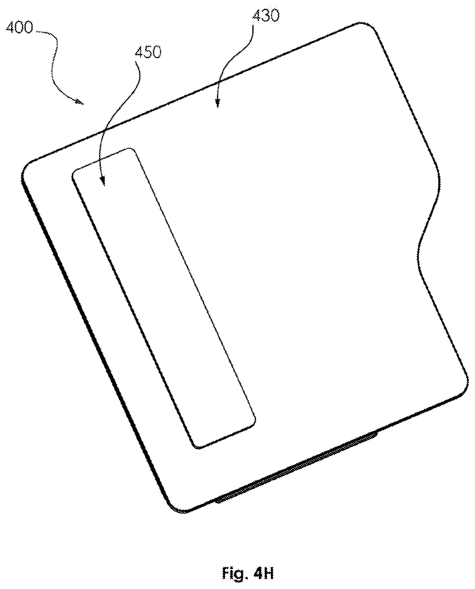
D00018

D00019

D00020

D00021
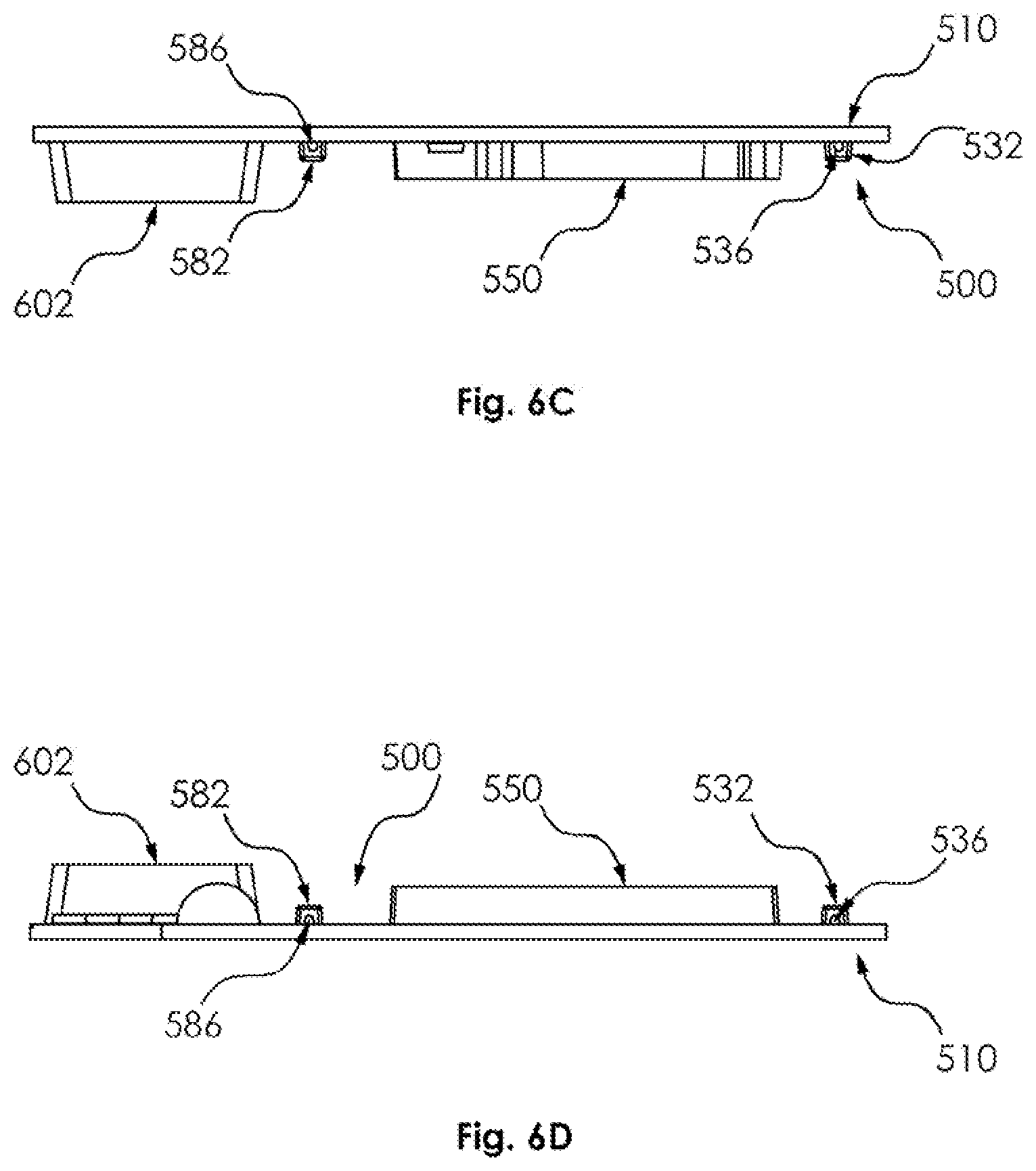
D00022

D00023

D00024

D00025

D00026

D00027

D00028

D00029

D00030

D00031

D00032

D00033

D00034

D00035

D00036

D00037

D00038

D00039
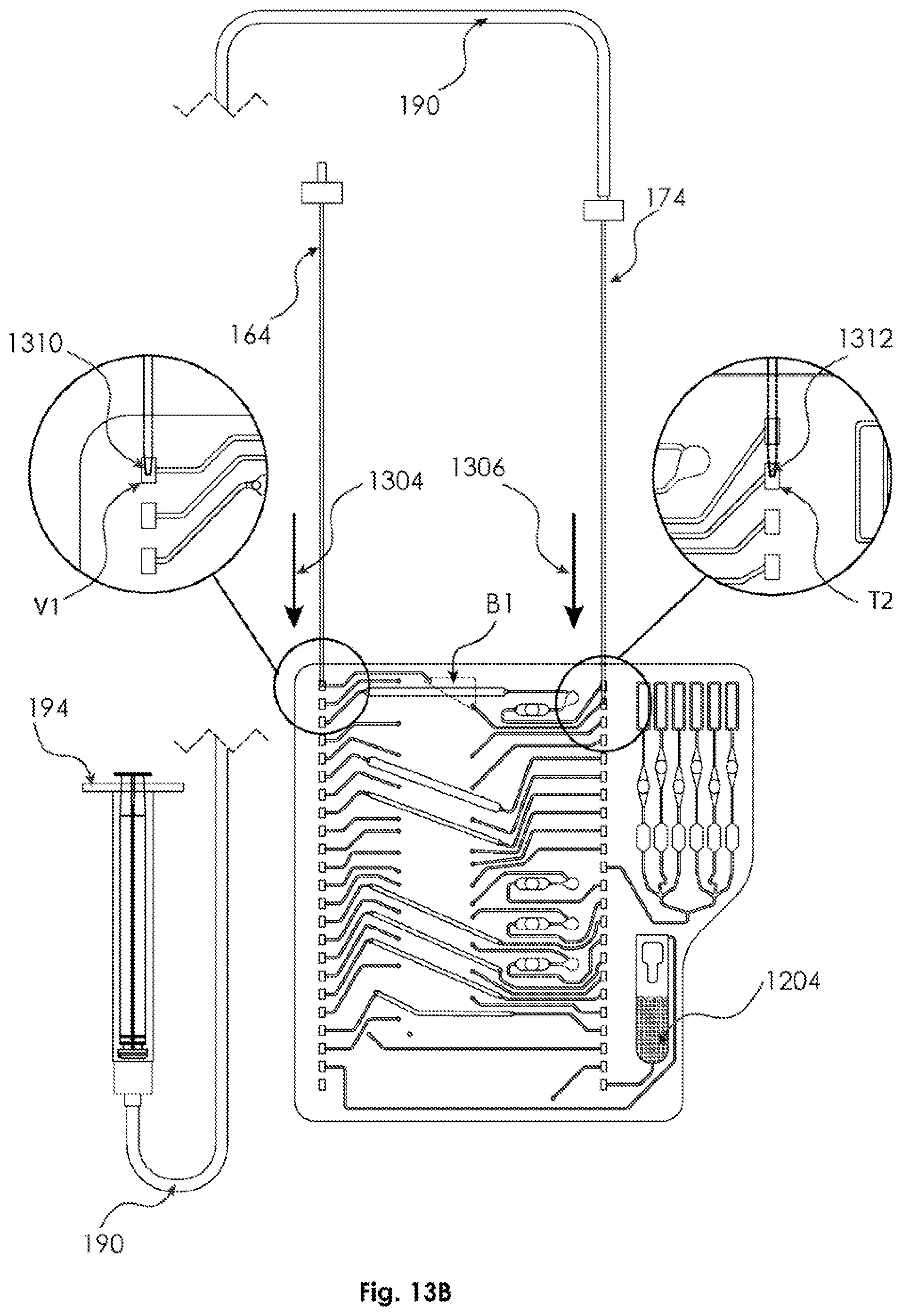
D00040
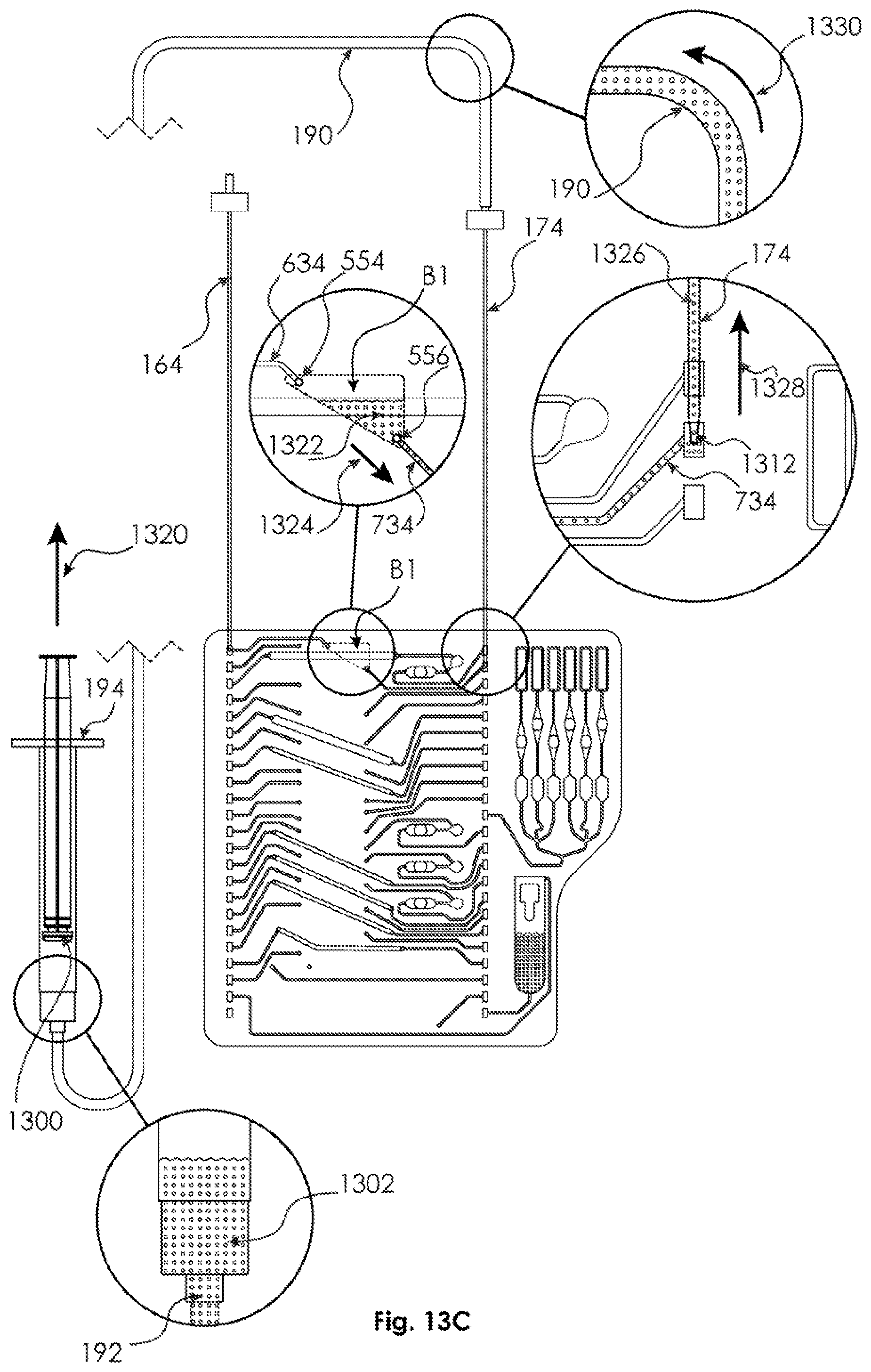
D00041

D00042
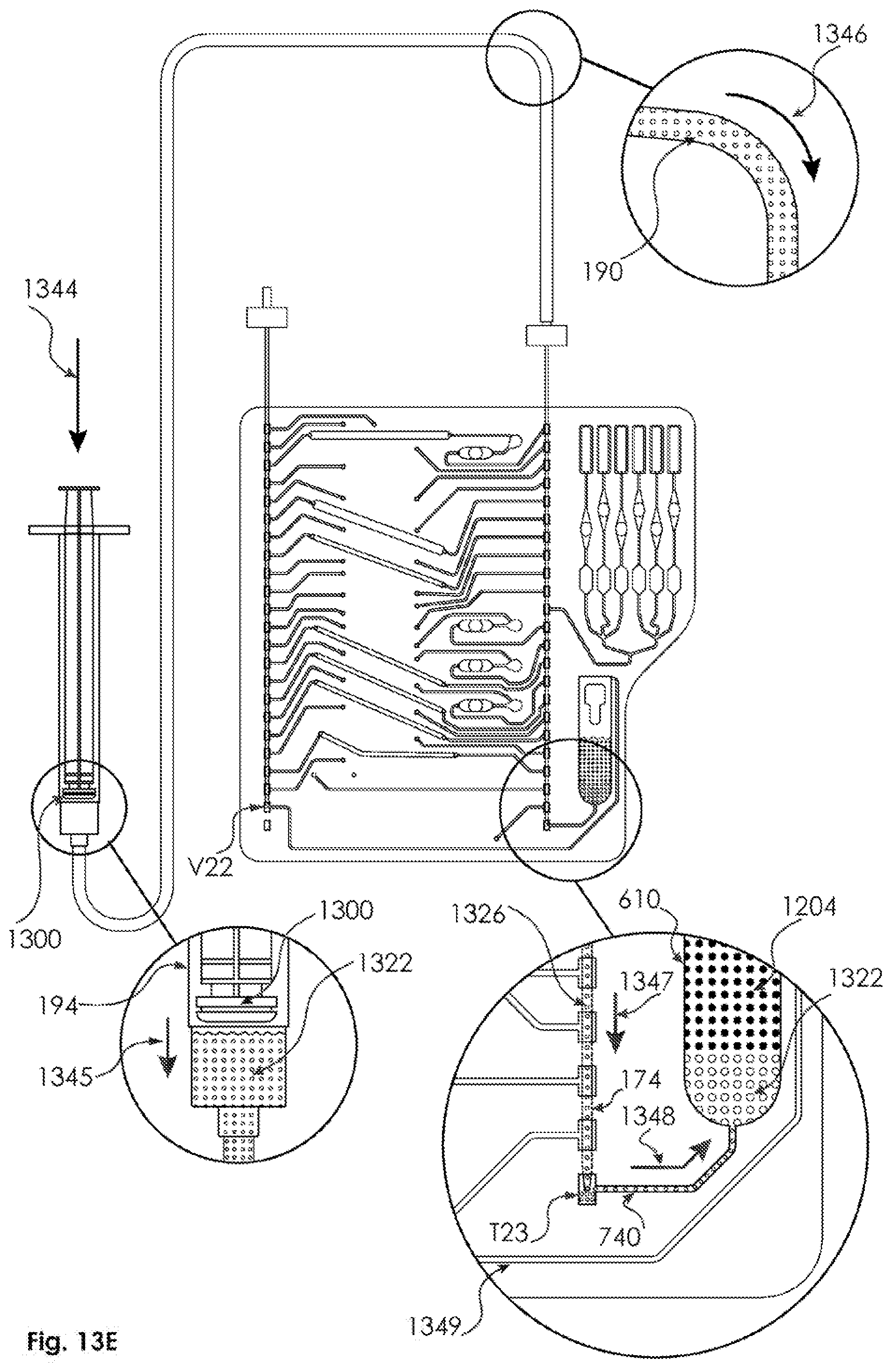
D00043

D00044

D00045

D00046
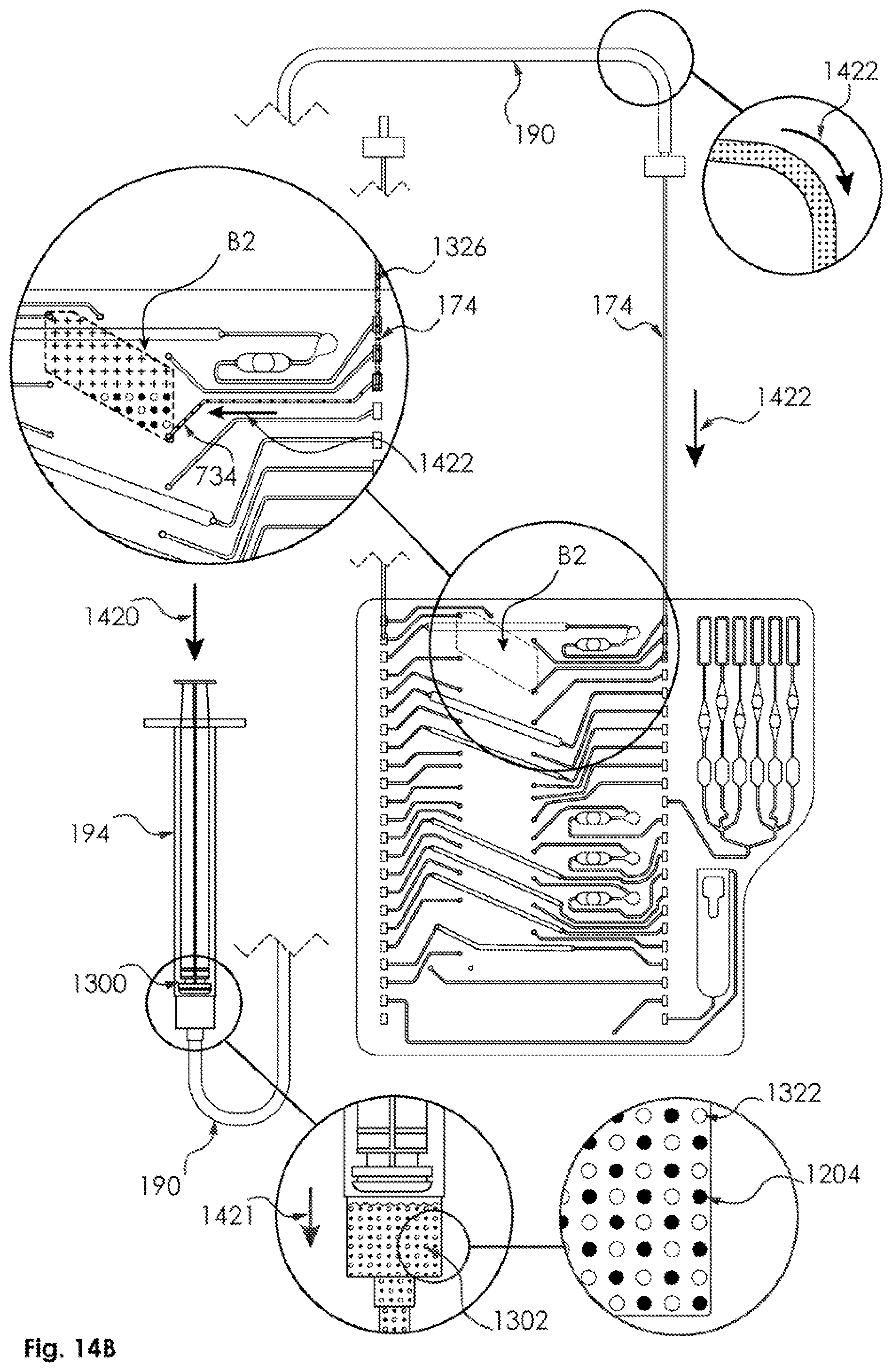
D00047

D00048
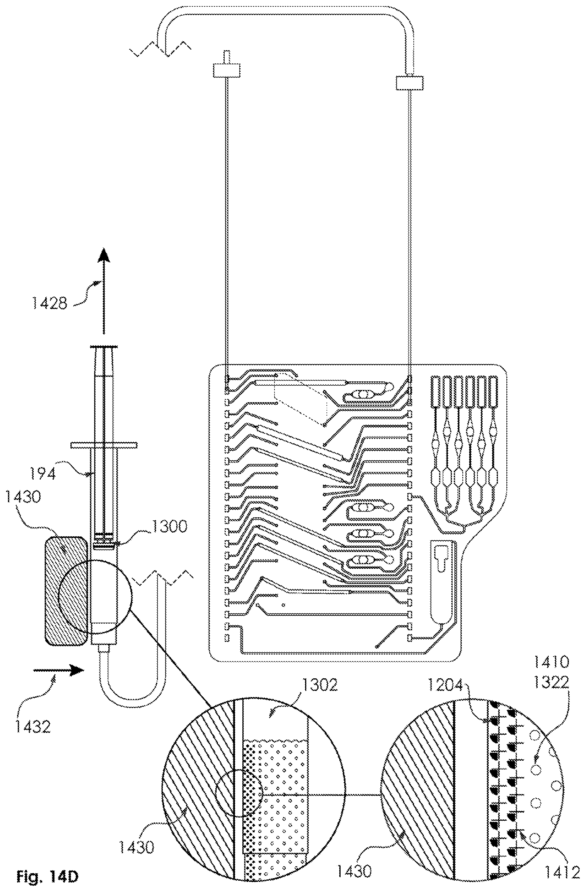
D00049
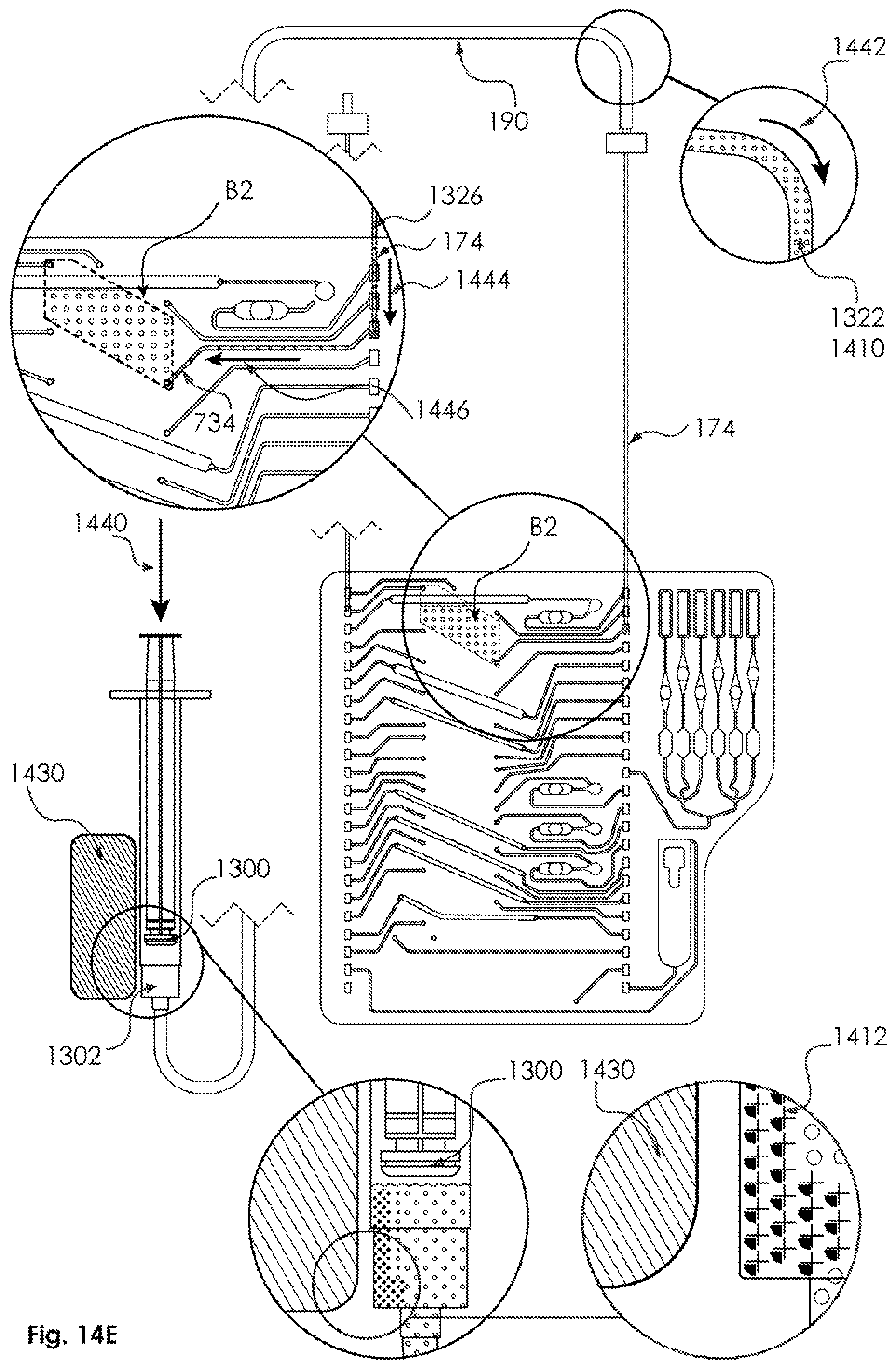
D00050

D00051

D00052

D00053
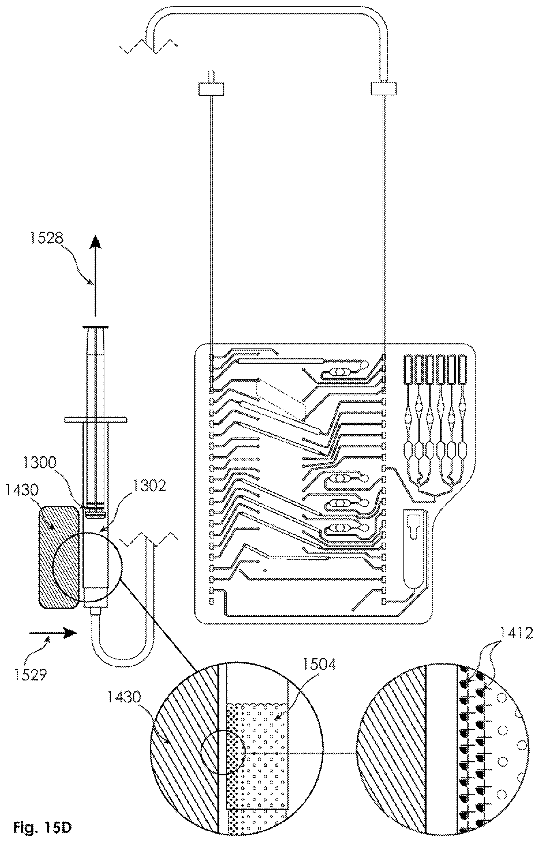
D00054

D00055

D00056

D00057

D00058
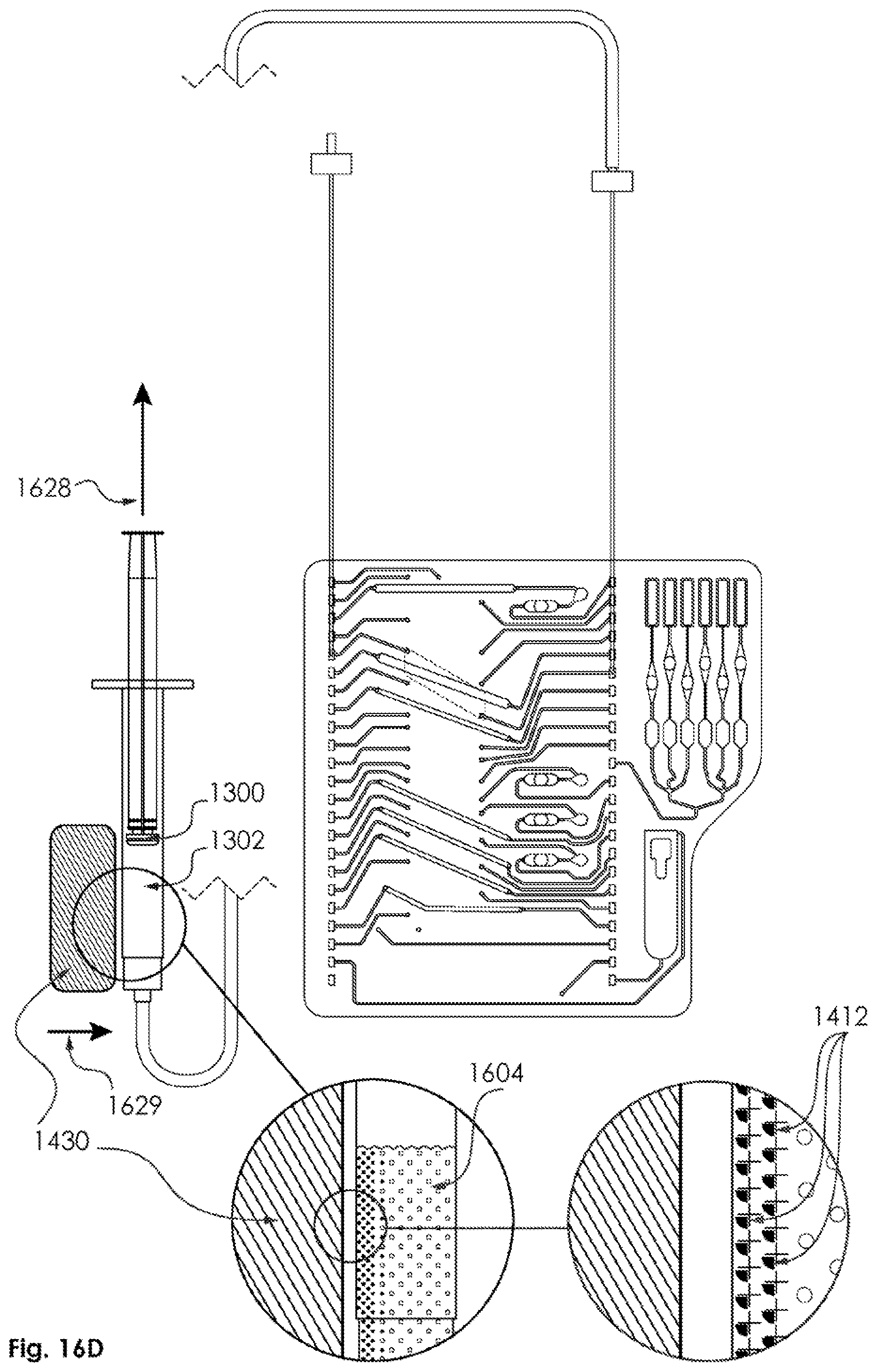
D00059
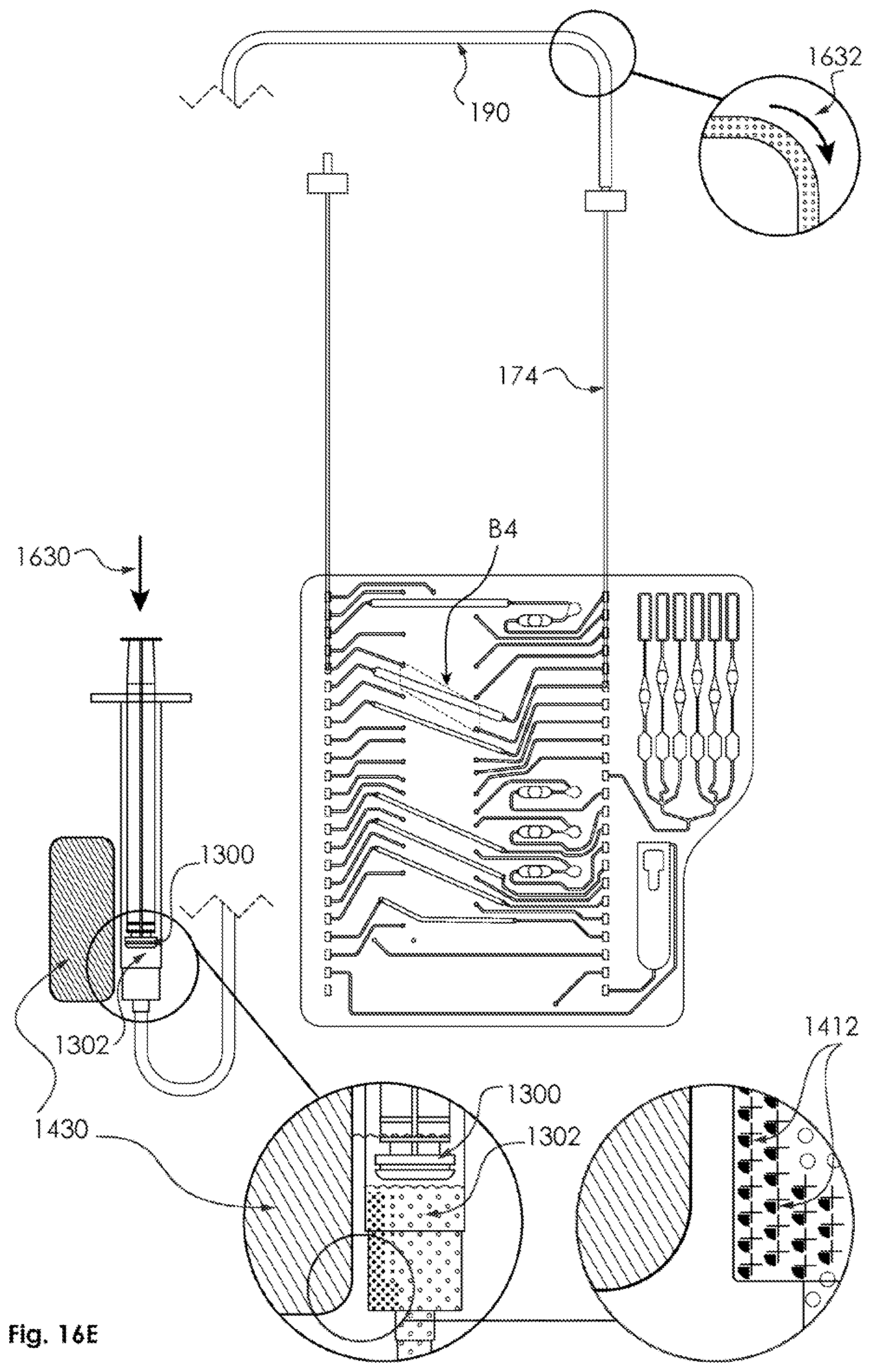
D00060
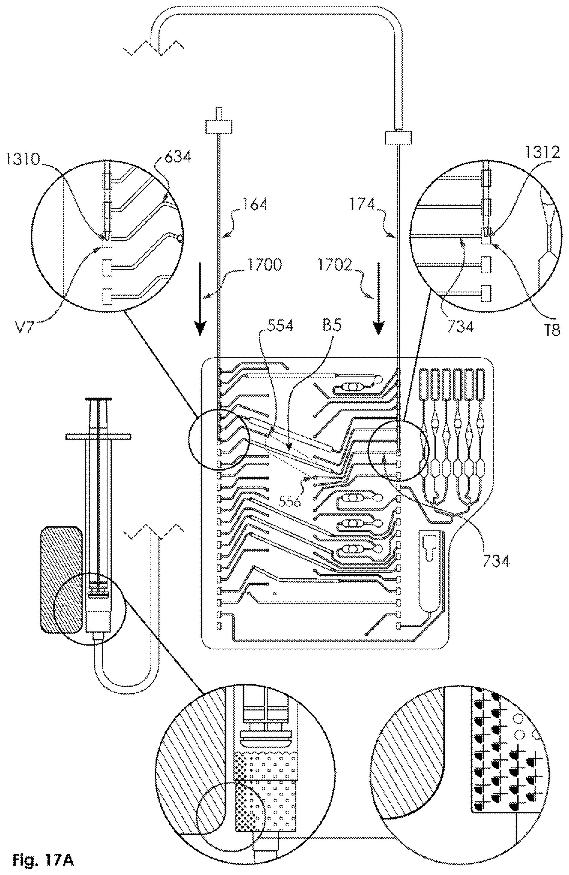
D00061

D00062

D00063

D00064

D00065

D00066

D00067

D00068

D00069

D00070

D00071

D00072

D00073

D00074

D00075

D00076

D00077

D00078

D00079

D00080
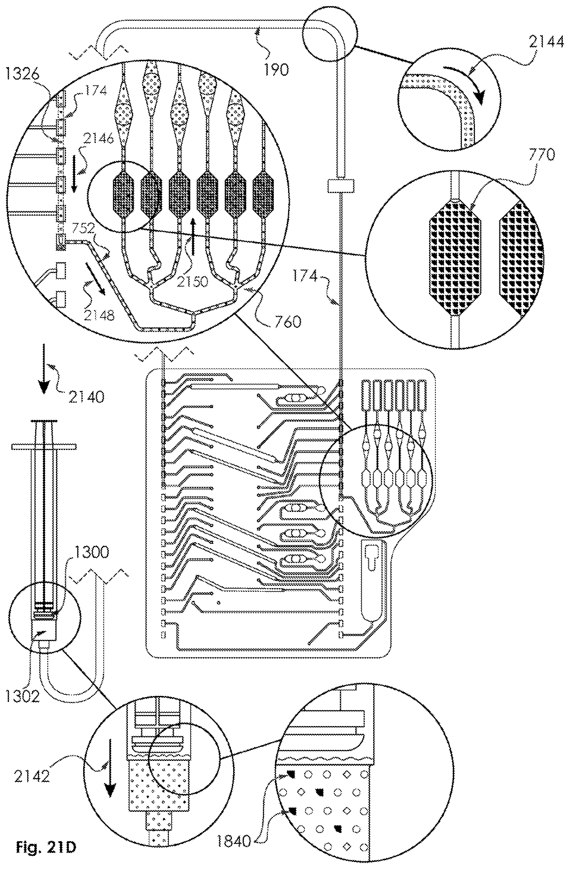
D00081
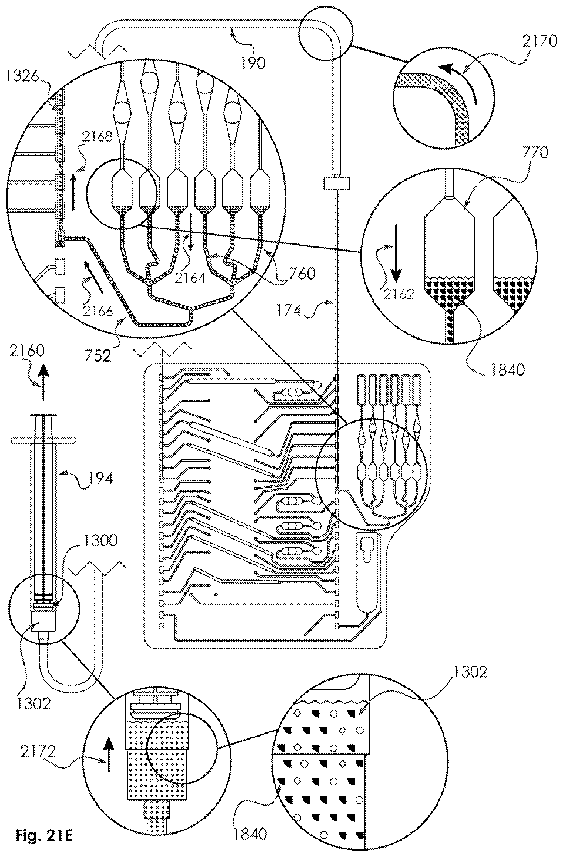
D00082

D00083

D00084

D00085
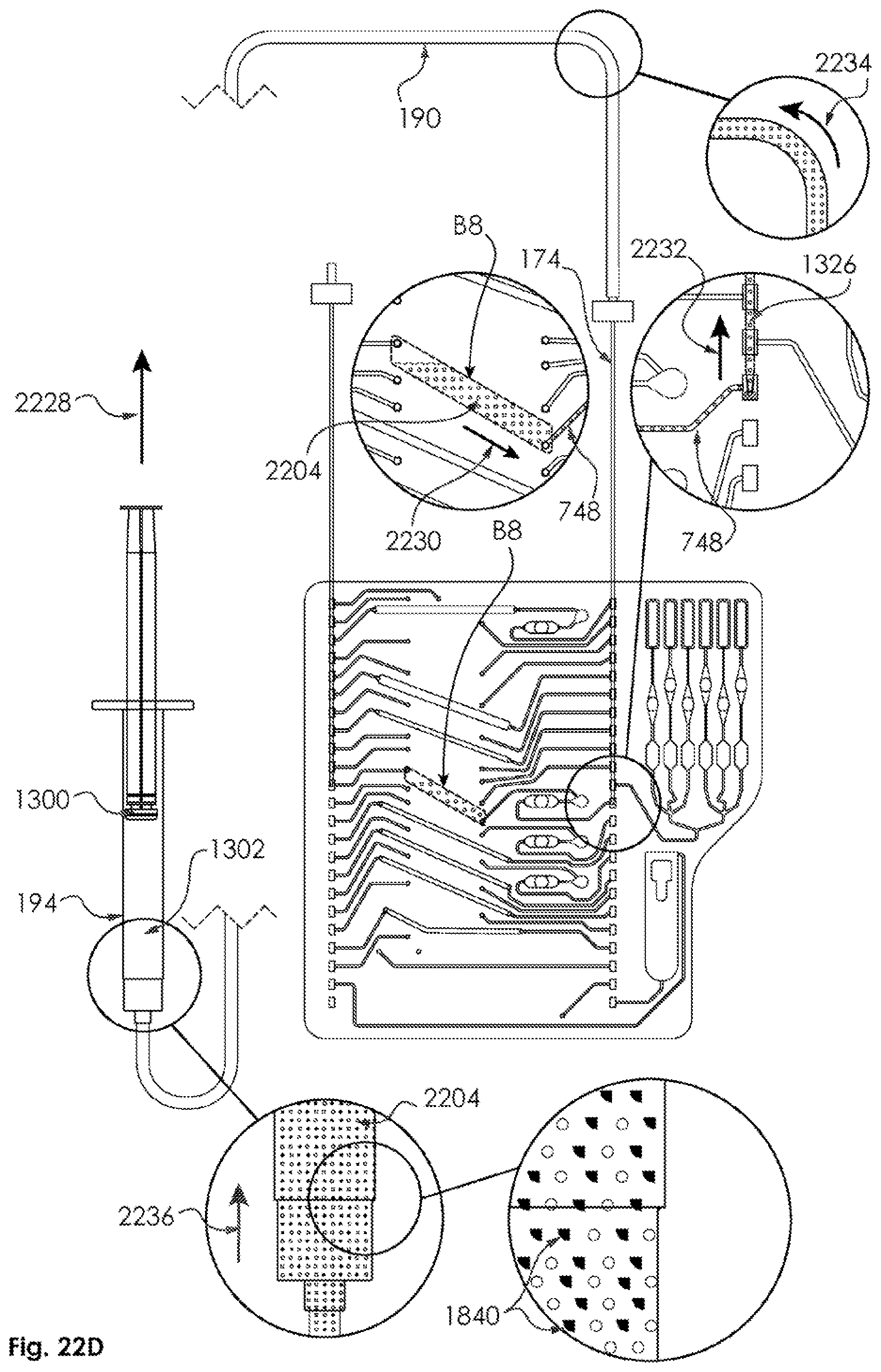
D00086
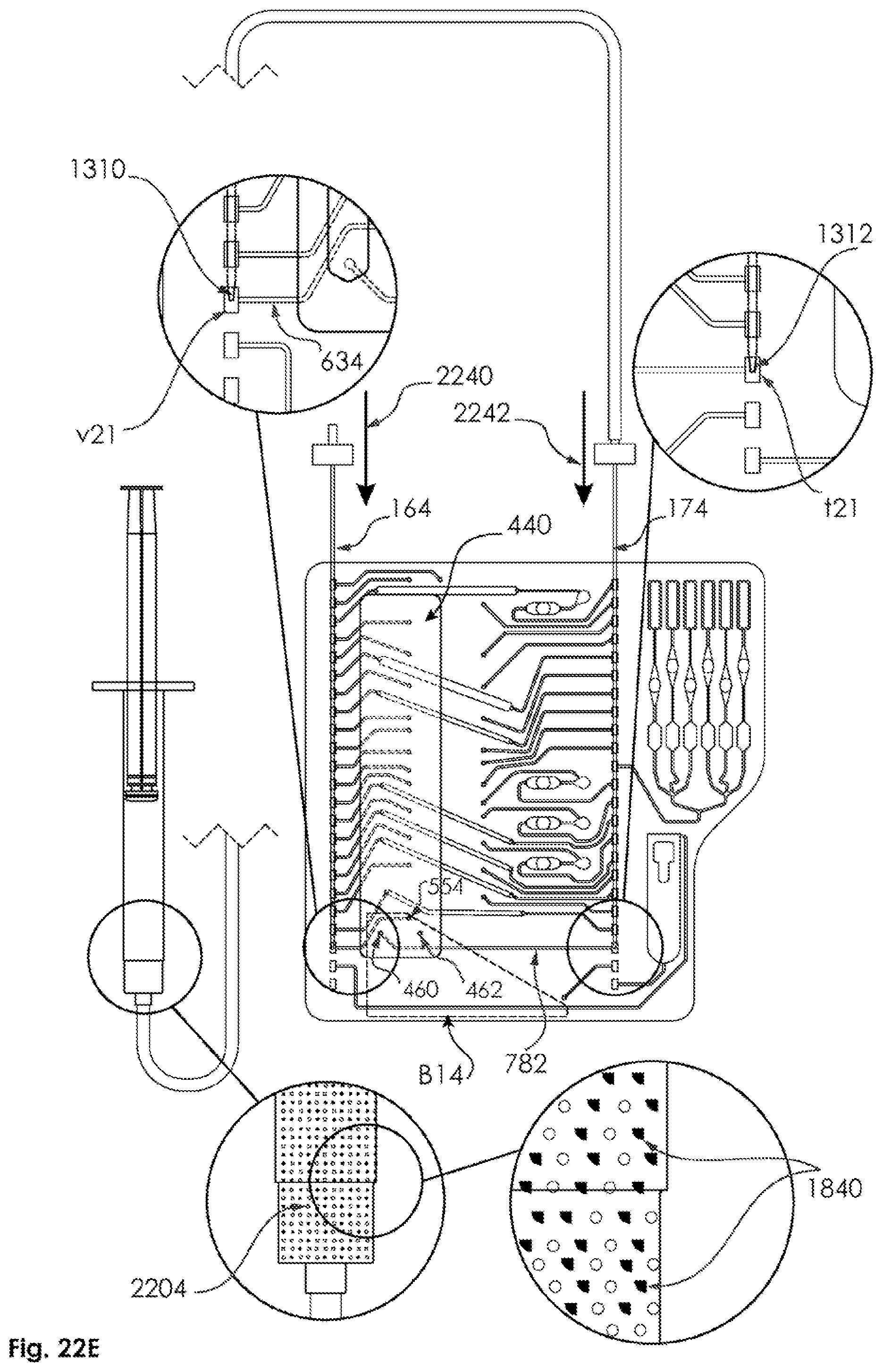
D00087

D00088

D00089

D00090

D00091
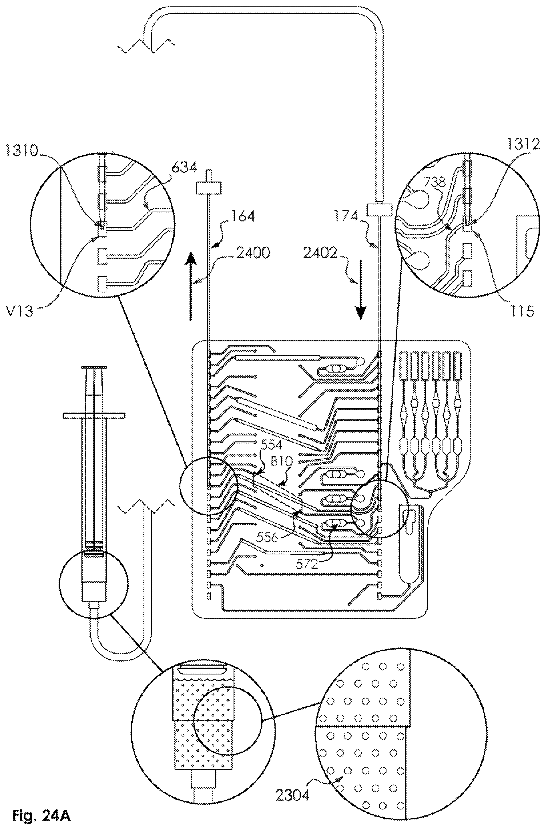
D00092

D00093

D00094

D00095

D00096

D00097

D00098
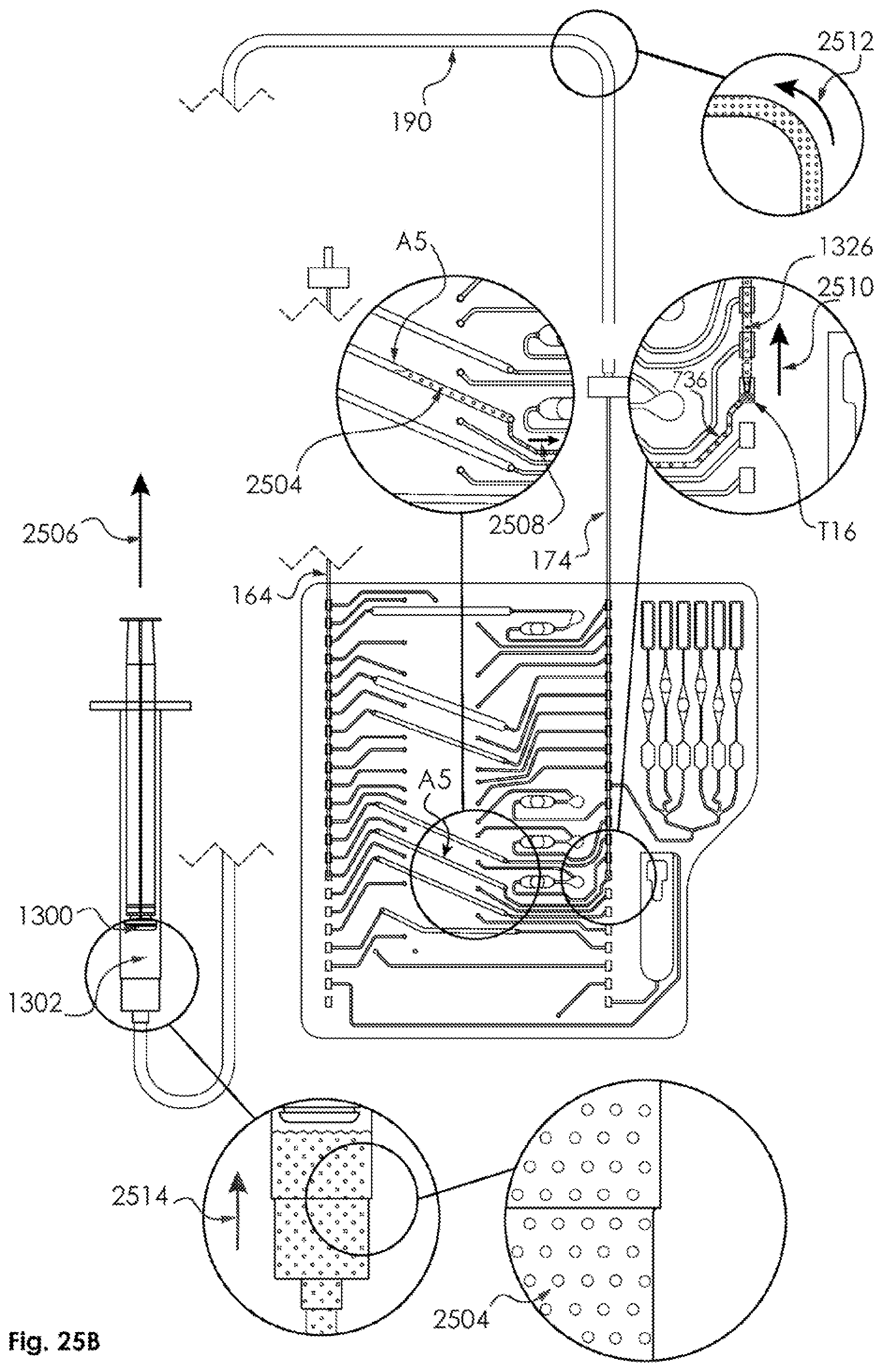
D00099

D00100

D00101

D00102

D00103

D00104

D00105

D00106

D00107

D00108
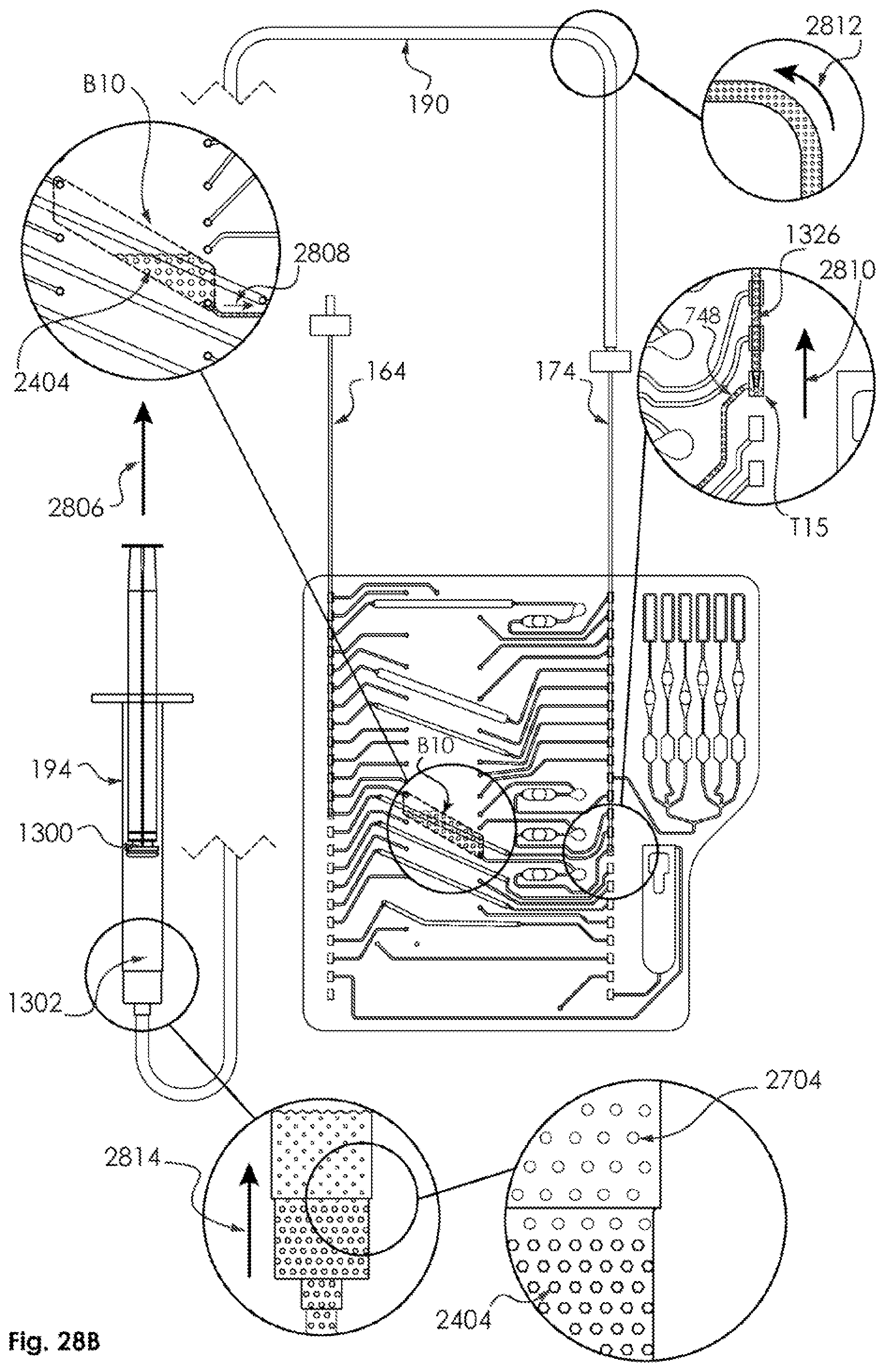
D00109

D00110
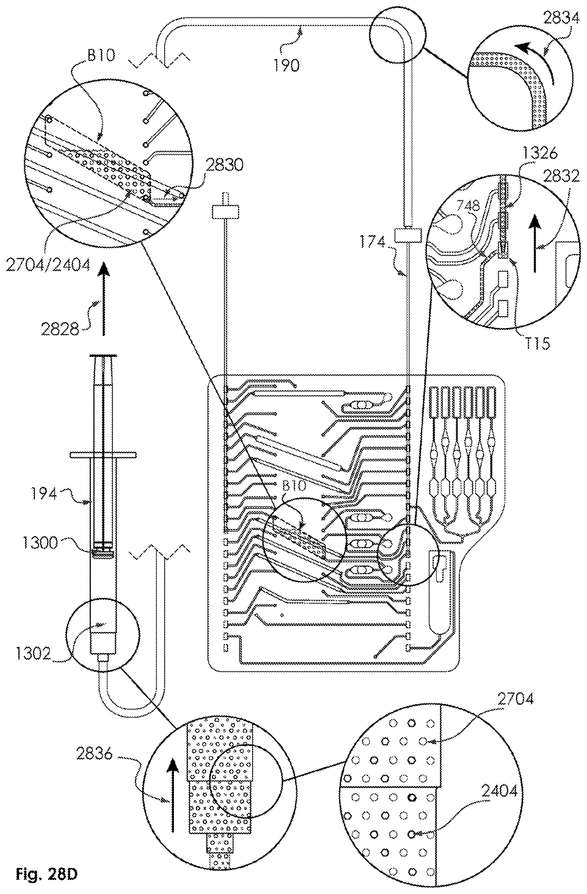
D00111

D00112

D00113

D00114

D00115

D00116

D00117

D00118

D00119

D00120

D00121
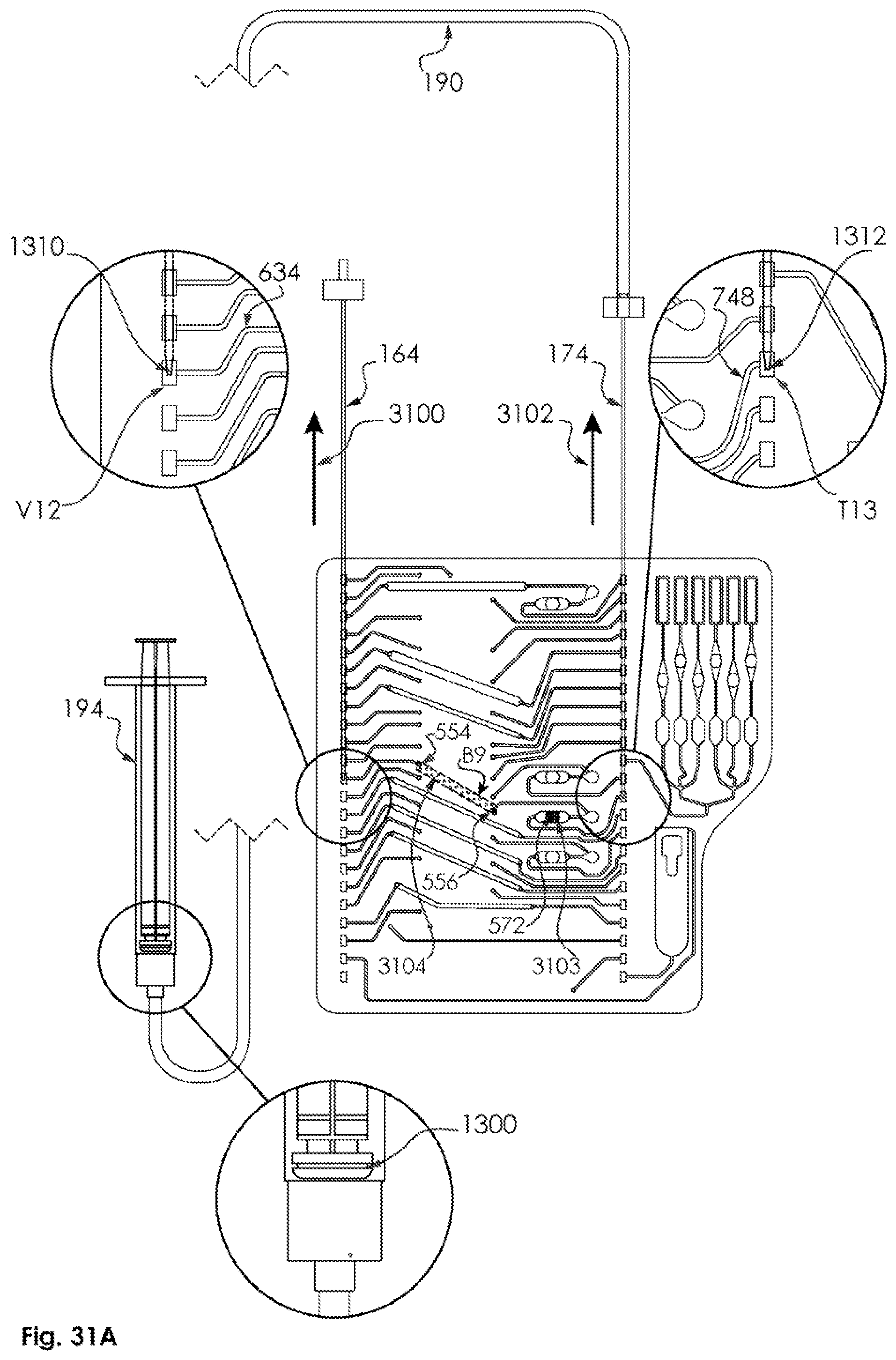
D00122

D00123

D00124

D00125

D00126

D00127

D00128

D00129

D00130

XML
uspto.report is an independent third-party trademark research tool that is not affiliated, endorsed, or sponsored by the United States Patent and Trademark Office (USPTO) or any other governmental organization. The information provided by uspto.report is based on publicly available data at the time of writing and is intended for informational purposes only.
While we strive to provide accurate and up-to-date information, we do not guarantee the accuracy, completeness, reliability, or suitability of the information displayed on this site. The use of this site is at your own risk. Any reliance you place on such information is therefore strictly at your own risk.
All official trademark data, including owner information, should be verified by visiting the official USPTO website at www.uspto.gov. This site is not intended to replace professional legal advice and should not be used as a substitute for consulting with a legal professional who is knowledgeable about trademark law.