System For Capturing And Recycling Carbon Dioxide In Exhaust Gas
CHANG; Won Seok ; et al.
U.S. patent application number 16/977961 was filed with the patent office on 2021-02-25 for system for capturing and recycling carbon dioxide in exhaust gas. This patent application is currently assigned to Korea District Heating Corp.. The applicant listed for this patent is Korea District Heating Corp.. Invention is credited to Won Seok CHANG, Yoon Soo CHOI, Kyung Min KIM, Young Jae LEE, Mun Sei OH, Ji Hye YU.
| Application Number | 20210053012 16/977961 |
| Document ID | / |
| Family ID | 1000005236589 |
| Filed Date | 2021-02-25 |

| United States Patent Application | 20210053012 |
| Kind Code | A1 |
| CHANG; Won Seok ; et al. | February 25, 2021 |
SYSTEM FOR CAPTURING AND RECYCLING CARBON DIOXIDE IN EXHAUST GAS
Abstract
The present invention provides a system for capturing and recycling carbon dioxide in an exhaust gas, which includes a CO.sub.2 capture unit into which an exhaust gas containing CO.sub.2 is input, and which captures the CO.sub.2 as a high concentration enriched gas and separates a first treatment gas; a mineralization process unit which mineralizes the CO.sub.2 after receiving the high concentration enriched gas captured in the CO.sub.2 capture unit and discharges a second treatment gas; a mixing tank which receives the first treatment gas and the second treatment gas and mixes them so that the contained CO.sub.2 has a predetermined concentration; a photo-culture process unit which receives the resulting third treatment gas from the mixing tank to perform a photo-culture process using microalgae; and a control unit which controls the flow rates and the CO.sub.2 contents of the gases supplied and discharged to/from the CO.sub.2 capture unit, the mineralization process unit, the mixing tank and the photo-culture process unit.
| Inventors: | CHANG; Won Seok; (Gyeonggi-do, KR) ; CHOI; Yoon Soo; (Gyeonggi-do, KR) ; OH; Mun Sei; (Seoul, KR) ; KIM; Kyung Min; (Gyeonggi-do, KR) ; YU; Ji Hye; (Incheon, KR) ; LEE; Young Jae; (Daejeon, KR) | ||||||||||
| Applicant: |
|
||||||||||
|---|---|---|---|---|---|---|---|---|---|---|---|
| Assignee: | Korea District Heating
Corp. Gyeonggi-do KR |
||||||||||
| Family ID: | 1000005236589 | ||||||||||
| Appl. No.: | 16/977961 | ||||||||||
| Filed: | November 7, 2018 | ||||||||||
| PCT Filed: | November 7, 2018 | ||||||||||
| PCT NO: | PCT/KR2018/013429 | ||||||||||
| 371 Date: | September 3, 2020 |
| Current U.S. Class: | 1/1 |
| Current CPC Class: | C12M 21/02 20130101; B01D 2255/802 20130101; C12M 43/04 20130101; B01D 2257/504 20130101; B01D 53/62 20130101; B01D 53/75 20130101; C12M 21/04 20130101; C01F 5/24 20130101; B01D 53/84 20130101; B01D 53/229 20130101; C01F 11/18 20130101 |
| International Class: | B01D 53/75 20060101 B01D053/75; B01D 53/22 20060101 B01D053/22; B01D 53/84 20060101 B01D053/84; B01D 53/62 20060101 B01D053/62; C01F 11/18 20060101 C01F011/18; C01F 5/24 20060101 C01F005/24; C12M 1/00 20060101 C12M001/00; C12M 1/107 20060101 C12M001/107 |
Foreign Application Data
| Date | Code | Application Number |
|---|---|---|
| Mar 6, 2018 | KR | 10-2018-0026373 |
Claims
1. A system for capturing and recycling carbon dioxide in an exhaust gas, comprising: a CO.sub.2 capture unit into which an exhaust gas containing CO.sub.2 is input, and which captures the CO.sub.2 at a high concentration as an enriched gas and separates a first treatment gas; a mineralization process unit which mineralizes the CO.sub.2 after receiving the high concentration enriched gas captured in the CO.sub.2 capture unit and discharges a second treatment gas; a mixing tank which receives the first treatment gas and the second treatment gas and mixes them so that the contained CO.sub.2 has a predetermined concentration; a photo-culture process unit which receives the resulting third treatment gas from the mixing tank to perform a photo-culture process using microalgae; and a control unit which controls the flow rates and the CO.sub.2 contents of the gases supplied and discharged to/from the CO.sub.2 capture unit, the mineralization process unit, the mixing tank and the photo-culture process unit.
2. The system of claim 1, wherein the control unit controls a CO.sub.2 concentration in the third treatment gas supplied from the mixing tank to 3 to 7%.
3. The system of claim 2, wherein the control unit controls a CO.sub.2 concentration in the mixing tank by adjusting an inflow amount of the first treatment gas.
4. The system of claim 1, wherein the enriched gas is supplied in a liquefied state.
5. A system for capturing and recycling carbon dioxide in an exhaust gas, comprising: an exhaust gas inlet into which an exhaust gas is input and which distributes the gas; a photo-culture process unit which receives the exhaust gas from the exhaust gas inlet to perform a photo-culture process using microalgae and discharge a fourth treatment gas; a mixing tank which receives the exhaust gas from the exhaust gas inlet and the fourth treatment gas and mixes them; a CO.sub.2 capture unit which receives the resulting fifth treatment gas from the mixing tank and captures CO.sub.2 contained in the fifth treatment gas at a high concentration as an enriched gas; a mineralization process unit which receives the enriched gas captured in the CO.sub.2 capture unit to mineralize the CO.sub.2, and discharges a sixth treatment gas; and a control unit which controls the flow rates and the CO.sub.2 contents of the gases supplied and discharged to/from the exhaust gas inlet, the photo-culture process unit, the mixing tank, the CO.sub.2 capture unit and the mineralization process unit, wherein the sixth treatment gas is input into the mixing tank.
6. The system of claim 5, wherein the control unit controls an amount of the exhaust gas supplied to the photo-culture process unit through the exhaust gas inlet by considering the CO.sub.2 treatment efficiency of the photo-culture process unit.
7. The system of claim 5, wherein the control unit controls the CO.sub.2 concentration of the mixed gas in the mixing tank to 8 to 10%.
8. The system of claim 5, wherein the enriched gas is supplied in a liquefied state.
Description
TECHNICAL FIELD
[0001] Embodiments relate to a system for capturing and recycling carbon dioxide in an exhaust gas. More particularly, embodiments relate to a system for capturing and recycling carbon dioxide in an exhaust gas, which is able to capture and recycle carbon dioxide in one system by considering the efficiency of each process to maximize the recycling efficiency of carbon dioxide.
BACKGROUND ART
[0002] With industrial development, the problem of global warming has emerged due to the increase in atmospheric carbon dioxide concentration, and the biggest cause of the increase in carbon dioxide concentration is the use of fossil fuels such as coal, oil and liquefied natural gas, which are used in the energy industry.
[0003] From the beginning of the 19.sup.th century when industrialization began, green gas concentrations such as carbon dioxide (CO.sub.2), methane (CH.sub.4), nitrogen dioxide, and halocarbons have increased in the atmosphere, and have rapidly increased from the mid-20.sup.th century.
[0004] As global warming is accelerating due to the increase in greenhouse gases, emission and disposal of these gases are more strictly regulated. Since the United Nations Framework Convention on Climate Change (UNFCCC) held in Rio de Janeiro in June 1992, international interest in global warming is gradually increasing, and an international consensus on greenhouse gas reduction was made, such that developed countries agreed in 2010 to reduce global greenhouse gas emissions by 5.2%, compared to 1990. Particularly, the treatment of CO.sub.2 accounting for approximately 80% of greenhouse gases causing global warming has become a more important issue.
[0005] Various technologies such as CO.sub.2 separation membrane capture technology, CO.sub.2 mineralization technology, and photo-culture technology using microalgae are emerging to treat the emitted CO.sub.2 component.
[0006] However, each technology has an advantage of treating CO.sub.2, but also has various problems such as system installation costs, CO.sub.2 throughput, and a low CO.sub.2 reduction rate per unit area.
DISCLOSURE
Technical Problem
[0007] Embodiments aim to treat carbon dioxide (CO.sub.2) capture and recycle in one linked system by considering the efficiency of each process to maximize CO.sub.2 recycling efficiency.
[0008] The problems to be solved in the present invention are not limited to the above-described problem, and other problems that are not mentioned herein will be clearly understood by those of ordinary skill in the art.
Technical Solution
[0009] One aspect of the present invention may provide a system for capturing and recycling CO.sub.2, which includes: a CO.sub.2 capture unit into which an exhaust gas containing CO.sub.2 is input, and which captures the CO.sub.2 at a high concentration as an enriched gas and separates a first treatment gas; a mineralization process unit which mineralizes the CO.sub.2 after receiving the high concentration enriched gas captured in the CO.sub.2 capture unit and discharges a second treatment gas; a mixing tank which receives the first treatment gas and the second treatment gas and mixes them so that the contained CO.sub.2 has a predetermined concentration; a photo-culture process unit which receives the resulting third treatment gas from the mixing tank to perform a photo-culture process using microalgae; and a control unit which controls the flow rates and the CO.sub.2 contents of the gases supplied and discharged to/from the CO.sub.2 capture unit, the mineralization process unit, the mixing tank and the photo-culture process unit. Preferably, the control unit may control a CO.sub.2 concentration in the third treatment gas supplied from the mixing tank to 3 to 7%.
[0010] Preferably, the control unit may control a CO.sub.2 concentration in the mixing tank by adjusting an inflow amount of the first treatment gas.
[0011] Preferably, the enriched gas may be supplied in a liquefied state.
[0012] In addition, in still another embodiment of the present invention, the present invention provides a system for capturing and recycling carbon dioxide in an exhaust gas, which includes: an exhaust gas inlet into which an exhaust gas is input and which distributes the gas; a photo-culture process unit which receives the exhaust gas from the exhaust gas inlet to perform a photo-culture process using microalgae and discharge a fourth treatment gas; a mixing tank which receives the exhaust gas from the exhaust gas inlet and the fourth treatment gas and mixes them; a CO.sub.2 capture unit which receives the resulting fifth treatment gas from the mixing tank and captures CO.sub.2 contained in the fifth treatment gas at a high concentration as an enriched gas; a mineralization process unit which receives the enriched gas captured in the CO.sub.2 capture unit to mineralize the CO.sub.2, and discharges a sixth treatment gas; and a control unit which controls the flow rates and the CO.sub.2 contents of the gases supplied and discharged to/from the exhaust gas inlet, the photo-culture process unit, the mixing tank, the CO.sub.2 capture unit and the mineralization process unit, wherein the sixth treatment gas is input into the mixing tank.
[0013] The control unit may control an amount of the exhaust gas supplied to the photo-culture process unit through the exhaust gas inlet by considering the CO.sub.2 treatment efficiency of the photo-culture process unit.
[0014] The control unit preferably controls the CO.sub.2 concentration of the mixed gas in the mixing tank to 8 to 10%.
[0015] The enriched gas is preferably supplied in a liquefied state.
Advantageous Effects
[0016] According to an embodiment, CO.sub.2 recycling efficiency can be enhanced.
[0017] In addition, the present invention has an effect of compensating for problems of CO.sub.2 separation membrane capture technology, CO.sub.2 mineralization technology and photo-culture technology using microalgae.
[0018] Various and beneficial advantages and effects of the present invention are not limited to those described above, and will be more easily understood during the description of specific embodiments of the present invention.
DESCRIPTION OF DRAWINGS
[0019] FIG. 1 is a block diagram of a system for capturing and recycling carbon dioxide in an exhaust gas according to an embodiment of the present invention.
[0020] FIG. 2 is a diagram showing an operation when a membrane separation process is used in a CO.sub.2 capture unit, which is a constituent of FIG. 1.
[0021] FIG. 3 is a schematic diagram of a first embodiment exhibiting an actual operation of the system of FIG. 1.
[0022] FIG. 4 is a schematic diagram of a second embodiment exhibiting an actual operation of the system of FIG. 1.
MODES OF THE INVENTION
[0023] The present invention may have various modifications and various examples, and thus specific examples are illustrated in the drawings and described in detail in the detailed description. However, it should be understood that the present invention is not limited to specific embodiments, and includes all modifications, equivalents or alternatives within the idea and technical scope of the present invention.
[0024] The ordinal numbers, for example, "first" and "second," may be used to describe various components, but the components should not be limited by these terms. The terms are used only to distinguish one component from another component. For example, without departing from the scope of rights of the embodiments, a second component may be referred to as a first component, and similarly, the first component may be referred to as a second component. The term "and/or" encompasses a combination of a plurality of related items described herein or any one of the plurality of related items described herein.
[0025] The terms used in the specification are used only to describe specific examples, not to limit the present invention. Singular expressions include plural expressions unless clearly indicated otherwise in the context. In the specification, it should be understood that the term "include" or "have" is intended to indicate the presence of a characteristic, number, step, action, component or part described in the specification, or a combination thereof, but does not preclude the possibility of the presence or addition of one or more other characteristics, numbers, steps, actions, components, parts or a combination thereof.
[0026] In the description of examples, when one element is described to be formed "on or under" another element, the "on or under" includes both cases in which two elements are brought into direct contact with each other or one or more other elements are indirectly disposed between the two elements. In addition, the expression "on or under" may also mean upward and downward based on one element.
[0027] Hereinafter, embodiments will be described in detail with reference to the accompanying drawings. However, the same reference numbers will be assigned to the same or corresponding elements regardless of the figure number, and the overlapping descriptions thereof will be omitted.
[0028] FIGS. 1 to 4 clearly show major characteristic parts to conceptually and clearly understand the present invention. As a result, various modifications in the diagrams are expected, and the scope of the present invention is not necessarily limited by the specific forms shown in the drawings.
[0029] FIG. 1 is a block diagram of a system for capturing and recycling carbon dioxide in an exhaust gas according to an embodiment of the present invention.
[0030] In one embodiment of the present invention, the system for capturing and recycling carbon dioxide in an exhaust gas may include a CO.sub.2 capture unit 100, a mineralization process unit 200, a photo-culture process unit 300 and a control unit 400.
[0031] The CO.sub.2 capture unit 100, which constitutes the present invention, may use separation membrane capture technology, and may be effectively used in CO.sub.2 capture in a power plant located on a small site in an expensive urban area. However, in the case of the CO.sub.2 capture unit 100 using the separation membrane capture technology, it is difficult to secure land for storing the captured CO.sub.2, and there is a problem of decreased stability.
[0032] The mineralization process unit 200 has advantages of mass-processing CO.sub.2 at high speed and semi-permanently treating CO.sub.2 by technology for enrichment and mineralization of CO.sub.2. However, to maximize a CO.sub.2 reduction rate, a high concentration CO.sub.2 supply source is needed.
[0033] In addition, a photo-culture process unit 300 has an advantage of producing higher value-added useful materials such as astaxanthin, .beta.-carotene, omega 3 and CGF through biological conversion of CO.sub.2 by technology of converting CO.sub.2 to biomass using microalgae. However, the photo-culture process using microalgae has a problem of a low CO.sub.2 reduction rate per unit area due to limitations in photosynthesis efficiency.
[0034] The system for capturing and recycling carbon dioxide in an exhaust gas according to an embodiment of the present invention is characterized by a structure that minimizes disadvantages of each constituent and emphasizes advantages thereof.
[0035] The CO.sub.2 capture unit 100 may separate CO.sub.2 from an exhaust gas and produce a high concentration of CO.sub.2.
[0036] In one embodiment, the CO.sub.2 capture unit 100 may use a separation membrane process.
[0037] The results of comparing conventional carbon capture and storage (CCS) technology with a separation membrane process are shown below.
TABLE-US-00001 TABLE 1 Processing Construction Operation Capture Land Classification time costs cost unit costs area CCS process 2~3 min 1.1 billion (won) 1.5 million/yr $80/tCO.sub.2 500~800 m.sup.2 Separation 15~20 min 900 million (won) 0.8 million/yr $40/tCo.sub.2 80~100 m.sup.2 membrane process
[0038] When CO.sub.2 is captured using a separation membrane capturing process, it can be seen that there are benefits in terms of processing time and processing cost, and confirmed that there is also a difference in land area for installing equipment.
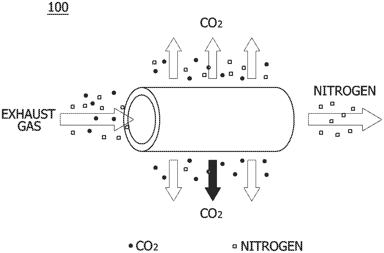
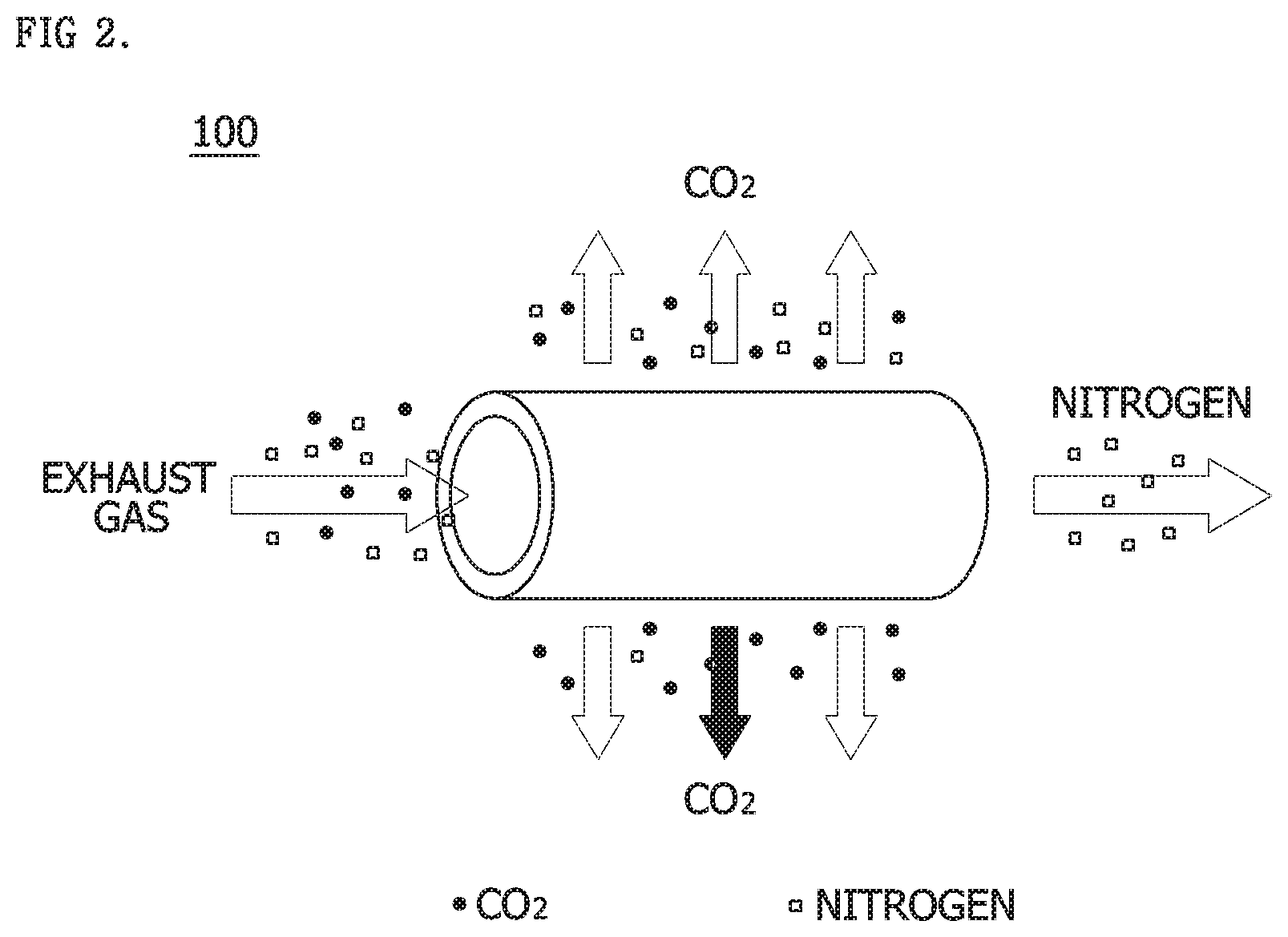
[0039] In the CO.sub.2 capture unit 100, when an exhaust gas enters a hollow fiber module formed of any one of various materials and flows through, various gas components (N.sub.2, O.sub.2, and CO.sub.2) may be captured at a high speed due to a difference in permeation rate.
[0040] FIG. 2 is a diagram showing an operation when a membrane separation process is used in a CO.sub.2 capture unit, which is a constituent of FIG. 1, and Table 2 is a table showing relative permeation rates of gases.
TABLE-US-00002 TABLE 2 H.sub.2O H.sub.2 H.sub.0 CO.sub.2 H.sub.2S O.sub.2 Ar CO N.sub.2 CH.sub.4 Fast <-------- Relative permeation rate of gas --------> Slow
[0041] Referring to both of FIG. 2 and Table 2, when the exhaust gas is supplied to the separation membrane, CO.sub.2 having a relatively high permeation speed is first discharged, and a slow nitrogen gas is later captured. The CO.sub.2 capture unit 100 using the membrane separation process may rapidly capture CO.sub.2 using such a principle.
[0042] In the mineralization process unit 200, a technique of reacting the captured CO.sub.2 with a natural mineral or inorganic industrial waste discharged in industry to synthesize a novel mineral.
[0043] In one embodiment, the mineralization process unit 200 may produce CaCO.sub.3, MgCO.sub.3 and a carbonate through mineralization of CO.sub.2 in the exhaust gas with Ca and
[0044] Mg components in construction by-products (slag and waste concrete), thereby permanently solidifying CO.sub.2.
[0045] The produced carbonate is stable and thus not soluble in water, since CO.sub.2 emission to the atmosphere is not possible, there is no harm to the environment, and CO.sub.2 is permanently stored to solve the CO.sub.2 emission issue.
[0046] In the photo-culture process unit 300, a CO.sub.2 fixation process may be performed using microalgae. Microalgae, which are phytoplankton, uses sunlight as an energy source, uses photosynthesis for fixing CO.sub.2 and thus grows.
[0047] The CO.sub.2 fixation using the microalgae may use solar energy as a main energy source as in the case in which a plant photosynthesizes CO.sub.2, and therefore energy consumption required to fix CO.sub.2 is very small.
[0048] Microalgae have a higher growth rate than plants, has a biomass productivity per unit area that is 20 to 100-fold higher than the first-generation biofuels such as soybean, corn and rapeseed, is able to be mass-cultured in salt water or wasteland, and is able to utilize various water resources such as sewage and seawater waste. Particularly, there is an advantage that a combustion exhaust gas discharged from a carbon emission source such as a thermal power plant can be directly utilized for cell culture.
[0049] The microalgae process can convert CO.sub.2 to various higher value-added materials such as biodiesel, a biopolymer, a medicine, health food and a natural pigment, and has an advantage that it is possible to develop an eco-friendly process with a low cost and economic feasibility due to no additional energy input by using solar light.
[0050] The microalgae that can be used for photo-culture may include Neochloris sp., Chlorella sp., Chlorococcum sp., Spirulina sp., Haematococcus sp., Neospongiococcum sp., Scenedesmus sp., Dunaliella sp. and thaustochytrids, but the present invention is not limited thereto. Generally, any microalgae having an ability to convert CO.sub.2 to biomass can be used without limitation.
[0051] The control unit 400 may control the flow rates and CO.sub.2 content of the gases supplied to the CO.sub.2 capture unit 100, the mineralization process unit 200 and the photo-culture process unit 300, and control operation of the entire system to enhance the efficiency of the entire process.
[0052] FIG. 3 is a schematic diagram of a first embodiment exhibiting an actual operation of the system of FIG. 1.
[0053] Referring to FIG. 3, the system for capturing and recycling carbon dioxide in an exhaust gas may include a CO.sub.2 capture unit 100 into which an exhaust gas containing CO.sub.2 is input, and which captures the CO.sub.2 at a high concentration as an enriched gas (G) and separates a first treatment gas (G1), a mineralization process unit 200 which mineralizes the CO.sub.2 after receiving the high concentration enriched gas G captured in the CO.sub.2 capture unit 100 and discharges a second treatment gas (G2), a mixing tank 500 which receives the first treatment gas (G1) and the second treatment gas (G2) and mixes them so that the contained CO.sub.2 has a predetermined concentration, a photo-culture process unit 300 which receives the resulting third treatment gas (G3) mixed in a state of enabling use by microalgae from the mixing tank 500 to perform a photo-culture process using microalgae, and a control unit 400 which controls the flow rates and the CO.sub.2 contents of the gases supplied and discharged to/from the CO.sub.2 capture unit 100, the mineralization process unit 200, the mixing tank 500 and the photo-culture process unit 300.
[0054] The CO.sub.2 capture unit 100 captures a high concentration of CO.sub.2 from the inflowing exhaust gas using a separation membrane process. Subsequently, the enriched gas (G) is supplied to the mineralization process unit 200, and the first treatment gas (G1) is introduced into the mixing tank 500. The enriched gas (G) may be supplied to the mineralization process unit 200 in the form of a liquefied carbonic acid gas (L-CO.sub.2).
[0055] The mineralization process unit 200 may produce various types of minerals such as a high calcium material and an aggregate using the high concentration enriched gas (G). The mineralization process unit 200 preferably has a CO.sub.2 treatment efficiency of 70 to 80%. The mineralization process unit 200 may supply the second treatment gas (G2) left after mineral production to the mixing tank 500.
[0056] The mixing tank 500 receives and mixes the first treatment gas (G1) and the second treatment gas (G2). Here, the control unit 400 may control a CO.sub.2 concentration in the third treatment gas (G3) supplied to the photo-culture process unit 300 from the mixing tank 500 to maximize the efficiency of the photo-culture process unit 300. In one embodiment, the CO.sub.2 concentration of the third treatment gas (G3) may be controlled to 3 to 7%.
[0057] Here, the control unit 400 may control CO.sub.2 in the mixing tank 500 by introducing the high concentration second treatment gas (G2) as it is into the mixing tank 500 and adjusting the inflow amount of the first treatment gas (G1). The control unit 400 may discharge a low concentration of the first treatment gas (G1) left after determination of the amount of the first treatment gas (G1) flowing into the mixing tank 500 according to a required concentration to the atmosphere.
[0058] The photo-culture process unit 300 receives the third treatment gas (G3) adjusted at an optimal proportion to perform a photo-culture process using microalgae, and after the process, the gas may be discharged into the atmosphere.
[0059] In an embodiment, when the inflowing exhaust gas having a CO.sub.2 concentration of 8% and a flow rate of 400 m.sup.3/hr is supplied, and the CO.sub.2 treatment efficiency of the CO.sub.2 capture unit 100 is 90%, the enriched gas (G) having a CO.sub.2 concentration of 90% may be supplied to the mineralization process unit 200 at a flow rate of 40 m.sup.3/hr. Here, the first treatment gas (G1) having a CO.sub.2 concentration of 1% may be introduced into the mixing tank 500 at a flow rate of 360 m.sup.3/hr.
[0060] When the CO.sub.2 treatment efficiency of a mineralization apparatus used in the mineralization process unit 200 is 80%, minerals may be produced from the enriched gas (G) having a CO.sub.2 concentration of 90%, and the second treatment gas (G2) having a CO.sub.2 concentration of 18% may be supplied to the mixing tank 500 at a flow rate of 40 m.sup.3/hr.
[0061] When the optimal CO.sub.2 concentration of the third treatment gas (G3) supplied to the photo-culture process unit 300 is 5%, the control unit 400 adjusts the concentration of the third treatment gas (G3) supplied from the mixing tank 500. In this case, the second treatment gas (G2) having a high CO.sub.2 content flow into the mixing tank 500 as it is, and the concentration of the mixing tank 500 may be adjusted by adjusting an inflow amount of the first treatment gas (G1). When the second treatment gas (G2) has a CO.sub.2 concentration of 18%, and is supplied at a flow rate of 40 m.sup.3/hr, the control unit 400 may adjust the concentration of the third treatment gas (G3) to 5% by adjusting the first treatment gas (G1) having a CO.sub.2 concentration of 1%, which has been supplied at a flow rate of 360 m.sup.3/hr, to be discharged at a flow rate of 240 m.sup.3/hr into the atmosphere and supplied to the mixing tank 500 at a flow rate of 120 m.sup.3/hr.
[0062] When the photo-culture process unit 300 has a CO.sub.2 treatment efficiency of 30%, a gas having a CO.sub.2 concentration of 3.5% is discharged into the atmosphere at a flow rate of 160 m.sup.3/hr.
[0063] In the entire process, when the first treatment gas (G1) discharged into the atmosphere is combined with the gas discharged from the photo-culture process unit 300, the total discharged gas may be discharged into the atmosphere at a flow rate of 400 m.sup.3/hr and a CO.sub.2 concentration of 2%.
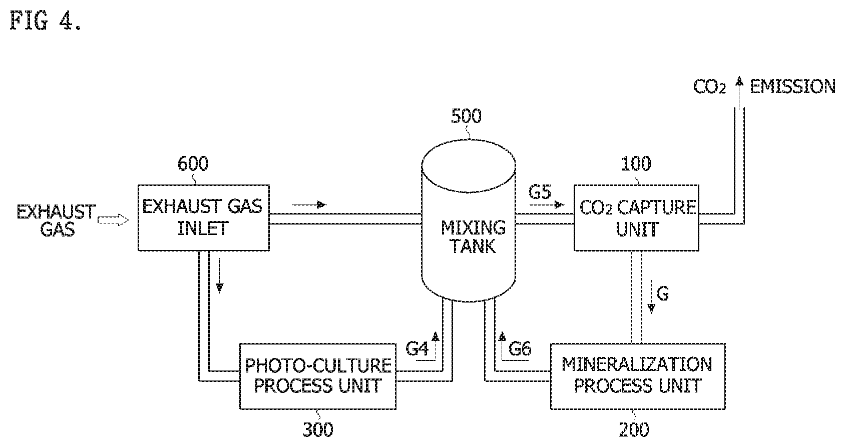
[0064] FIG. 4 is a schematic diagram of a second embodiment exhibiting an actual operation of the system of FIG. 1.
[0065] Referring to FIG. 4, a system for capturing and recycling carbon dioxide in an exhaust gas according to the second embodiment of the present invention may include an exhaust gas inlet 600 into which an exhaust gas is input and which distributes the gas, a photo-culture process unit 300 which receives the exhaust gas from the exhaust gas inlet 600 to perform a photo-culture process using microalgae and discharge a fourth treatment gas (G4), a mixing tank 500 which receives and mixes the exhaust gas from the exhaust gas inlet 600 and the fourth treatment gas (G4), a CO.sub.2 capture unit 100 which receives the resulting fifth treatment gas (G5) from the mixing tank 500 and captures CO.sub.2 contained in the fifth treatment gas (G5) at a high concentration as an enriched gas (G), a mineralization process unit 200 which receives the enriched gas (G) captured in the CO.sub.2 capture unit 100 to mineralize the CO.sub.2, and discharges a sixth treatment gas (G6), and a control unit 400 which controls the flow rates and the CO.sub.2 contents of the gases supplied and discharged to/from the exhaust gas inlet 600, the photo-culture process unit 300, the mixing tank 500, the CO.sub.2 capture unit 100 and the mineralization process unit 200, wherein the sixth treatment gas (G6) is input into the mixing tank 500.
[0066] The exhaust gas inlet 600 may distribute an exhaust gas input from an industrial facility to the photo-culture process unit 300 and the mixing tank 500. Here, the control unit 400 may control an amount of the exhaust gas input to the photo-culture process unit 300 in consideration of the concentration of the mixed gas supplied to the CO.sub.2 capture unit 100 from the mixing tank 500 by considering the CO.sub.2 treatment efficiency of the photo-culture process unit 300. Here, the control unit 400 may adjust the amount of the exhaust gas supplied to the photo-culture process unit 300 by also considering the concentration of the sixth treatment gas (G6) supplied to the mixing tank 500 from the mineralization process unit 200.
[0067] The photo-culture process unit 300 may produce biomass by performing a photo-culture process using microalgae after the exhaust gas is received, and the processed fourth treatment gas (G4) may be input to the mixing tank 500.
[0068] The mixing tank 500 mixes the exhaust gas which is supplied from the exhaust gas inlet 600, the fourth treatment gas (G4), and the sixth treatment gas (G6) supplied from the mineralization process unit 200, and the mixed gas may be supplied to the CO.sub.2 capture unit 100. The CO.sub.2 concentration in the mixed gas may be controlled to 8 to 10% by the control unit 400.
[0069] The CO.sub.2 capture unit 100 captures a high concentration of CO.sub.2 from the mixed gas introduced from the mixing tank 500 using a separation membrane process. Afterward, the enriched gas (G) may be supplied to the mineralization process unit 200, and the processed gas may be discharged into the atmosphere. In one embodiment, the enriched gas (G) may be supplied in a liquefied state.
[0070] The mineralization process unit 200 may receive the enriched gas (G) from the CO.sub.2 capture unit 100 to produce various types of minerals such as a high calcium material and an aggregate. The mineralization process unit 200 preferably has CO.sub.2 treatment efficiency of 70 to 80%. The mineralization process unit 200 may supply the sixth treatment gas (G6) left after the mineral production to the mixing tank 500. A cycling procedure is created such that the mineralization process unit 200 processes the enriched gas (G) supplied from CO.sub.2 capture unit 100 and inputs the sixth treatment gas (G6) to the mixing tank 500, and the mixing tank 500 recombines the sixth treatment gas (G6) to be supplied to the CO.sub.2 capture unit 100.
[0071] In one embodiment, when the exhaust gas having a CO.sub.2 concentration of 8% is supplied to the exhaust gas inlet 600 at a flow rate of 400 m.sup.3/hr, the control unit 400 may supply the gas to the photo-culture process unit 300 having a CO.sub.2 treatment efficiency of 30% at a flow rate of 100 m.sup.3/hr, and the remainder of the gas may be supplied to the mixing tank 500 at a flow rate of 300 m.sup.3/hr.
[0072] The photo-culture process unit 300 produces biomass using microalgae, and supplies the fourth treatment gas (G4) having a CO.sub.2 concentration of 5.5% and a flow rate of 100 m.sup.3/hr to the mixing tank 500.
[0073] The mixing tank 500 may mix a gas supplied from the exhaust gas inlet 600, the fourth treatment gas (G4), and the sixth treatment gas (G6) having a CO.sub.2 concentration of 18% supplied to the mineralization process unit 200 at a flow rate of 40 m.sup.3/hr, and supply the mixed gas having a CO.sub.2 concentration of 8 to 10% to the CO.sub.2 capture unit 100 at a flow rate of 400 m.sup.3/hr.
[0074] The CO.sub.2 capture unit 100 having a CO.sub.2 treatment efficiency of 90% may supply the enriched gas (G) having a CO.sub.2 concentration of 90% to the mineralization reaction unit at a flow rate of 40 m.sup.3/hr, and the processed gas having a CO.sub.2 concentration of 1% may be discharged into the atmosphere at a flow rate of 360 to 400 m.sup.3/hr.
[0075] In the first embodiment shown in FIG. 3, although the concentration of CO.sub.2 finally discharged into the atmosphere is high as 2%, the entire process is sequentially carried out so that the energy consumption is lowered.
[0076] However, in the second embodiment shown in FIG. 4, although the concentration of CO.sub.2 finally discharged into the atmosphere is low as 1%, to construct a cycling structure of the mineralization reaction unit, the energy consumption increases as compared to the first embodiment.
[0077] As above, the embodiments of the present invention have been described in detail with reference to the accompanying drawings.
[0078] The above description only exemplifies the technical spirit of the present invention, and it will be understood by those of ordinary skill in the art that the present invention can be modified, altered and substituted in various forms without departing from the essential features of the present invention. Therefore, the embodiments disclosed in the present invention and the accompanying drawings are not intended to limit the technical spirit of the present invention, but to explain the scope of the technical spirit of the present invention. The scope of the present invention is construed with reference to the following claims, and all technical spirit within the equivalent range thereto will be construed as being included in the scope of rights of the present invention.
EXPLANATION OF REFERENCE NUMERALS IN THE DRAWINGS
[0079] 100: CO.sub.2 capture unit, 200: mineralization process unit, 300: photo-culture process unit, 400: control unit, 500: mixing tank, 600: exhaust gas inlet
* * * * *
D00000
D00001
D00002
D00003
D00004
XML
uspto.report is an independent third-party trademark research tool that is not affiliated, endorsed, or sponsored by the United States Patent and Trademark Office (USPTO) or any other governmental organization. The information provided by uspto.report is based on publicly available data at the time of writing and is intended for informational purposes only.
While we strive to provide accurate and up-to-date information, we do not guarantee the accuracy, completeness, reliability, or suitability of the information displayed on this site. The use of this site is at your own risk. Any reliance you place on such information is therefore strictly at your own risk.
All official trademark data, including owner information, should be verified by visiting the official USPTO website at www.uspto.gov. This site is not intended to replace professional legal advice and should not be used as a substitute for consulting with a legal professional who is knowledgeable about trademark law.