Midline Catheter Placement Device
Isaacson; Shawn Ray ; et al.
U.S. patent application number 16/996769 was filed with the patent office on 2021-02-25 for midline catheter placement device. The applicant listed for this patent is Becton, Dickinson and Company. Invention is credited to Weston Finch Harding, Shawn Ray Isaacson, Charles D. Shermer, Daniel M. Stipe.
| Application Number | 20210052858 16/996769 |
| Document ID | / |
| Family ID | 1000005049684 |
| Filed Date | 2021-02-25 |


View All Diagrams
| United States Patent Application | 20210052858 |
| Kind Code | A1 |
| Isaacson; Shawn Ray ; et al. | February 25, 2021 |
Midline Catheter Placement Device
Abstract
A catheter insertion device is provided for positioning and inserting a catheter, particularly a midline catheter into a patient. The insertion device includes an actuator assembly movable with respect to a housing for deploying the catheter over a needle. A step-wise movement of the actuator advances a catheter assembly, including the catheter, in stages over the introducer needle. An indexing finger of the catheter assembly engages the actuator body during distal advancement of the actuator, and deflects as the actuator is moved proximally. The device further includes a lockout device such as a button, collar, slider, or tab, which allows movement of the catheter relative to the needle but prevents advancement of the catheter to the first stage of the step-wise movement.
| Inventors: | Isaacson; Shawn Ray; (Layton, UT) ; Harding; Weston Finch; (Lehi, UT) ; Shermer; Charles D.; (Raleigh, NC) ; Stipe; Daniel M.; (Raleigh, NC) | ||||||||||
| Applicant: |
|
||||||||||
|---|---|---|---|---|---|---|---|---|---|---|---|
| Family ID: | 1000005049684 | ||||||||||
| Appl. No.: | 16/996769 | ||||||||||
| Filed: | August 18, 2020 |
Related U.S. Patent Documents
| Application Number | Filing Date | Patent Number | ||
|---|---|---|---|---|
| 62888946 | Aug 19, 2019 | |||
| Current U.S. Class: | 1/1 |
| Current CPC Class: | A61M 25/0606 20130101; A61M 25/0097 20130101 |
| International Class: | A61M 25/06 20060101 A61M025/06; A61M 25/00 20060101 A61M025/00 |
Claims
1. A catheter placement device, comprising: a housing; a needle extending from a distal end of the housing; a catheter assembly disposed coaxially over the needle, including a catheter supported by a catheter hub, and a safety assembly including a first indexing finger; and an actuator assembly configured to transition longitudinally between a first position and a second position, the actuator assembly comprising: an actuator button extending through an elongate opening in the housing; and an actuator body including a plurality of actuator abutments, wherein the first indexing finger engages a first actuator abutment of the plurality of actuator abutments and the actuator assembly distally advances the catheter assembly in a stepwise manner as the actuator assembly moves between the first position and the second position.
2. The catheter placement device according to claim 1, wherein the first indexing finger is integrally molded with the safety assembly to form a single structure, the first indexing finger configured to flexibly deform as the actuator body moves from the second position to the first position.
3. The catheter placement device according to claim 1, wherein the first indexing finger is supported by a collar and is formed as a separate structure from the safety assembly, the collar being coupled to the safety assembly, and the first indexing finger configured to flexibly deform as the actuator body moves from the second position to the first position.
4. The catheter placement device according to claim 1, wherein the housing includes a plurality of housing tabs that engage the safety assembly to prevent proximal movement thereof.
5. The catheter placement device according to claim 1, wherein the housing includes a plurality of housing abutments that engage a second indexing finger extending from the safety assembly to prevent proximal movement thereof.
6. The catheter placement device according to claim 1, wherein the actuator body includes a top wall, a first side wall, and a second side wall that define an inverse channel through which the catheter assembly moves along a longitudinal axis.
7. The catheter placement device according to claim 6, wherein one of the first side wall or the second side wall includes a plurality of notches that define the plurality of actuator abutments.
8. The catheter placement device according to claim 6, wherein one of the first side wall or the second side wall includes a plurality of apertures that define the plurality of actuator abutments.
9. The catheter placement device according to claim 1, wherein the housing includes a first door and a second door disposed at a distal end thereof and configured to pivot through a horizontal plane between an open position and a closed position.
10. The catheter placement device according to claim 9, wherein the housing includes a first housing half and a second housing half joined along a longitudinally vertical plane, the first door hingedly coupled to the first housing half and the second door hingedly coupled to the second housing half.
11. The catheter placement device according to claim 1, wherein the housing includes a first hinged door disposed at a distal end thereof and configured to pivot through a vertical plane.
12. The catheter placement device according to claim 11, wherein the housing includes a first housing half and a second housing half j oined along a longitudinally horizontal plane, the first door hingedly coupled to the first housing half.
13. The catheter placement device according to claim 1, further comprising a lockout device that transitions between a locked position and an unlocked position, the locked position allowing a movement of the catheter relative to the needle and restricting distal advancement of the catheter assembly in the stepwise manner.
14. The catheter placement device according to claim 13, wherein the movement of the catheter relative to the needle is restricted to less than a longitudinal distance between the first actuator abutment and a second actuator abutment, adjacent to the first actuator abutment.
15. The catheter placement device according to claim 13, wherein the movement of the catheter relative to the needle is restricted to less than half a longitudinal distance between the first actuator abutment and a second actuator abutment, adjacent to the first actuator abutment.
16. The catheter placement device according to claim 13, wherein the movement of the catheter relative to the needle is restricted to a distance of between 1 mm to 3 mm.
17. The catheter placement device according to claim 13, wherein the lockout device includes a lockout button including an engagement arm having a first aperture defining a first diameter, and a second aperture defining a second diameter, the second diameter being larger than the first diameter, the first aperture communicating with the second aperture to define a keyhole shape that receives an anchor portion of the safety assembly therethrough.
18. The catheter placement device according to claim 17, wherein the lockout button transitions between the locked position and an unlocked position, the anchor portion is disposed within the first aperture in the locked position and the second aperture in the unlocked position.
19. The catheter placement device according to claim 18, wherein the anchor portion includes a flange that extends radially from a proximal end of the anchor portion, the flange defining a diameter that is larger than the first diameter and smaller than the second diameter, the flange abuts against the engagement arm when the lockout button is in the locked position.
20. The catheter placement device according to claim 13, wherein the lockout device includes a lockout collar slidably engaged with an outer surface of the housing and transitions longitudinally between the locked position and the unlocked position.
21. The catheter placement device according to claim 20, wherein the lockout collar encircles a longitudinal axis of the housing, the lockout collar covering a portion of the elongate opening in the locked position to restrict movement of the actuator assembly.
22. The catheter placement device according to claim 20, wherein the lockout collar is disposed between the actuator button and a first protrusion in the locked position, and between the first protrusion and a second protrusion in the unlocked position.
23. The catheter placement device according to claim 13, wherein the lockout device includes a lockout slider disposed on the actuator button and slides perpendicular to a longitudinal axis to engage a notch, when in the locked position.
24. The catheter placement device according to claim 23, wherein a longitudinal width of the slider is less than a longitudinal width of the notch to allow movement of the actuator button in the locked position and restrict distal advancement of the catheter assembly in the stepwise manner.
25. The catheter placement device according to claim 23, wherein the lockout slider in the unlocked position aligns with the actuator button to disengage the notch and allow the actuator assembly to move between the first position and the second position.
26. The catheter placement device according to claim 13, wherein the lockout device includes a lockout tab interposed between the actuator assembly and the housing in the locked position, which restricts movement of the actuator assembly.
27. The catheter placement device according to claim 23, wherein the lockout tab extends through a slot in the housing, the tab defining a longitudinal width that is less than a longitudinal length of the slot.
28. A method of inserting a catheter, comprising: providing a catheter insertion device, comprising: a housing; a needle extending from a distal end of the housing; an actuator assembly including an actuator button and an actuator body; a catheter assembly disposed coaxially over the needle, comprising: a catheter supported by a catheter hub; and a safety assembly; and a lockout device transitionable between a locked position and an unlocked position, the locked position permitting movement of the catheter relative to the needle and inhibiting advancement of the catheter in a stepwise manner; actuating the actuator button with the lockout device in the locked position to move the catheter relative to the needle; transitioning the lockout device from the locked position to the unlocked position; inserting the needle into a patient to access a vasculature thereof; and actuating the actuator button from a first position to a second position to advance the catheter in the stepwise manner relative to the needle.
29. The method according to claim 28, wherein the actuator body includes a plurality of actuator abutments, and the safety assembly includes an indexing finger, the indexing finger engaging an actuator abutment of the plurality of actuator abutments as the actuator button moves from the first position to the second position, and the indexing finger deflecting as the actuator button moves from the second position to the first position.
30. A method of advancing a catheter over a needle, comprising: providing a catheter placement device, comprising: a housing including a plurality of housing tabs and a needle extending from a distal end thereof; a catheter assembly including a catheter disposed coaxially over the needle and engaging a first housing tab of the plurality of housing tabs; an actuator assembly configured to move between a first position and a second position to advance the catheter assembly from the first housing tab to a second housing tab adjacent to the first housing tab; and a lockout device transitionable between a locked position and an unlocked position, the locked position restricting movement of the catheter assembly between the first housing tab and the second housing tab, the unlocked position permitting movement of the catheter assembly between the first housing tab and the second housing tab; actuating the actuator button with the lockout device in the locked position to move the catheter relative to the needle while preventing the catheter assembly from advancing from the first housing tab to the second housing tab; transitioning the lockout device from the locked position to the unlocked position; inserting the needle into a patient to access a vasculature thereof; and actuating the actuator button from the first position to the second position to advance the catheter assembly from the first housing tab to the second housing tab.
31. The method according to claim 30, wherein the lockout device is one of a lockout button, a lockout collar, a lockout slider and a lockout tab.
32. The method according to claim 30, wherein the housing includes a first hinged door and a second hinged door, each disposed at the distal end of the housing and configured to pivot to an open position to release the catheter hub.
Description
PRIORITY
[0001] This application claims the benefit of priority to U.S. Provisional Application No. 62/888,946, filed Aug. 19, 2019, which is incorporated by reference in its entirety into this application.
BACKGROUND
[0002] Midline catheters are generally used for parenteral nutrition, intravenous ("IV") fluid replacement and the administration of analgesics and antibiotics. Midline catheters are inserted at the bedside using sterile techniques and can remain in place for several weeks. The insertion (venipuncture) can be performed above and below the antecubital fossa in the cephalic, basilic, or brachial veins. The catheter tip is advanced 3 inches to 8 inches with the tip terminating below the axilla and proximal central veins.
[0003] The potential advantages of a midline catheter are the reduced frequency of repeated venipunctures for labs/restarts, decreased incidence of catheter related infections, extended implant/indwell duration, improved clinical outcomes, patient satisfaction and associated cost savings. Placing the catheter tip in the larger diameter veins in the upper arm compared to the smaller veins provide improved drug delivery therapy and hemodilution. Midline catheters can be used for infusing contrast media at higher flow rates that are typically done by central venous ("CV") catheters such as peripherally inserted central venous catheter ("PICC") applications.
[0004] Prior midline catheter devices typically include an integral guidewire. The guidewire is advanced through the lumen of the needle and into the vein after the needle accesses the vein. Often an ultrasonic probe or imaging device is used to locate the needle in the desired location. The catheter is then advanced over the guidewire into the vein. The needle and guidewire are then detached and separated from the catheter which remains in place in the vein.
[0005] These prior devices generally require the guidewire to be fully deployed by moving a sliding member into a locked/detent position. To advance the catheter, the user must put down the ultrasonic probe and use both hands to advance the catheter and complete the final steps of the procedure. This results in a loss of the visualization of the vein and the location of the catheter relative to the vein.
[0006] Catheter placement and advancement is dependent on holding the device in a stationary position with one hand while manipulating the catheter advancing mechanism in the other hand without the use of the ultrasonic imaging to assist in proper placement of the catheter. Once the catheter is fully advanced, the user must re-position the ultrasonic probe to re-establish the image and confirm proper placement of the catheter. The operation requires a series of sequential steps with specialized training. The additional exchange of hand positions from the ultrasonic probe to the device and back to the probe adds complexity to the procedure and risks the success of the proper placement of the catheter.
[0007] What is needed, therefore is a catheter placement device that streamlines the steps involved in catheter placement, as well as being operated with a single hand, while still providing the same functionality of current catheter placement devices.
SUMMARY
[0008] Briefly summarized, embodiments disclosed herein are directed to extended dwell peripheral IV catheter ("PIVC") devices that provide a longer length "mini-midline" catheter. The catheter would be placed similarly to a PIVC, without the need for a guidewire and would only require one-handed operation. Placement would be carried out under ultrasound imaging guidance and can access deeper vessels or facilitate difficult venous access ("DVA") procedures. The catheter would be able to successfully extend the dwell time for patients requiring medium/long term IV therapy, for example between 5 and 30 days.
[0009] Disclosed herein is a catheter placement device including, a housing, a needle extending from a distal end of the housing, a catheter assembly disposed coaxially over the needle, including a catheter supported by a catheter hub, and a safety assembly including a first indexing finger, and an actuator assembly configured to transition longitudinally between a first position and a second position, the actuator assembly including, an actuator button extending through an elongate opening in the housing, and an actuator body including a plurality of actuator abutments, wherein the first indexing finger engages a first actuator abutment of the plurality of actuator abutments and the actuator assembly distally advances the catheter assembly in a stepwise manner as the actuator assembly moves between the first position and the second position.
[0010] In some embodiments, the first indexing finger is integrally molded with the safety assembly to form a single structure, the first indexing finger configured to flexibly deform as the actuator body moves from the second position to the first position. The first indexing finger is supported by a collar and is formed as a separate structure from the safety assembly, the collar being coupled to the safety assembly, and the first indexing finger configured to flexibly deform as the actuator body moves from the second position to the first position. The housing includes a plurality of housing tabs that engage the safety assembly to prevent proximal movement thereof. The housing includes a plurality of housing abutments that engage a second indexing finger extending from the safety assembly to prevent proximal movement thereof.
[0011] In some embodiments, the actuator body includes a top wall, a first side wall, and a second side wall that define an inverse channel through which the catheter assembly moves along a longitudinal axis. One of the first side wall or the second side wall includes a plurality of notches that define the plurality of actuator abutments. One of the first side wall or the second side wall includes a plurality of apertures that define the plurality of actuator abutments. The housing includes a first door and a second door disposed at a distal end thereof and configured to pivot through a horizontal plane between an open position and a closed position. The housing includes a first housing half and a second housing half joined along a longitudinally vertical plane, the first door hingedly coupled to the first housing half and the second door hingedly coupled to the second housing half.
[0012] In some embodiments, the housing includes a first hinged door disposed at a distal end thereof and configured to pivot through a vertical plane. The housing includes a first housing half and a second housing half joined along a longitudinally horizontal plane, the first door hingedly coupled to the first housing half. In some embodiments, the catheter placement device further includes a lockout device that transitions between a locked position and an unlocked position, the locked position allowing a movement of the catheter relative to the needle and restricting distal advancement of the catheter assembly in the stepwise manner. The movement of the catheter relative to the needle is restricted to less than a longitudinal distance between the first actuator abutment and a second actuator abutment, adjacent to the first actuator abutment. The movement of the catheter relative to the needle is restricted to less than half a longitudinal distance between the first actuator abutment and a second actuator abutment, adjacent to the first actuator abutment. The movement of the catheter relative to the needle is restricted to a distance of between 1 mm to 3 mm.
[0013] In some embodiments, the lockout device includes a lockout button including an engagement arm having a first aperture defining a first diameter, and a second aperture defining a second diameter, the second diameter being larger than the first diameter, the first aperture communicating with the second aperture to define a keyhole shape that receives an anchor portion of the safety assembly therethrough. The lockout button transitions between the locked position and an unlocked position, the anchor portion is disposed within the first aperture in the locked position and the second aperture in the unlocked position. The anchor portion includes a flange that extends radially from a proximal end of the anchor portion, the flange defining a diameter that is larger than the first diameter and smaller than the second diameter, the flange abuts against the engagement arm when the lockout button is in the locked position.
[0014] In some embodiments, the lockout device includes a lockout collar slidably engaged with an outer surface of the housing and transitions longitudinally between the locked position and the unlocked position. The lockout collar encircles a longitudinal axis of the housing, the lockout collar covering a portion of the elongate opening in the locked position to restrict movement of the actuator assembly. The lockout collar is disposed between the actuator button and a first protrusion in the locked position, and between the first protrusion and a second protrusion in the unlocked position. The lockout device includes a lockout slider disposed on the actuator button and slides perpendicular to a longitudinal axis to engage a notch, when in the locked position. A longitudinal width of the slider is less than a longitudinal width of the notch to allow movement of the actuator button in the locked position and restrict distal advancement of the catheter assembly in the stepwise manner.
[0015] In some embodiments, the lockout slider in the unlocked position aligns with the actuator button to disengage the notch and allow the actuator assembly to move between the first position and the second position. The lockout device includes a lockout tab interposed between the actuator assembly and the housing in the locked position, which restricts movement of the actuator assembly. The lockout tab extends through a slot in the housing, the tab defining a longitudinal width that is less than a longitudinal length of the slot.
[0016] Also disclosed is a method of inserting a catheter including, providing a catheter insertion device having a housing, a needle extending from a distal end of the housing, an actuator assembly including an actuator button and an actuator body, a catheter assembly disposed coaxially over the needle having, a catheter supported by a catheter hub and a safety assembly, and a lockout device transitionable between a locked position and an unlocked position, the locked position permitting movement of the catheter relative to the needle and inhibiting advancement of the catheter in a stepwise manner, actuating the actuator button with the lockout device in the locked position to move the catheter relative to the needle, transitioning the lockout device from the locked position to the unlocked position, inserting the needle into a patient to access a vasculature thereof, and actuating the actuator button from a first position to a second position to advance the catheter in the stepwise manner relative to the needle.
[0017] In some embodiments, the actuator body includes a plurality of actuator abutments, and the safety assembly includes an indexing finger, the indexing finger engaging an actuator abutment of the plurality of actuator abutments as the actuator button moves from the first position to the second position, and the indexing finger deflecting as the actuator button moves from the second position to the first position.
[0018] Also disclosed is a method of advancing a catheter over a needle including, providing a catheter placement device having, a housing including a plurality of housing tabs and a needle extending from a distal end thereof, a catheter assembly including a catheter disposed coaxially over the needle and engaging a first housing tab of the plurality of housing tabs, an actuator assembly configured to move between a first position and a second position to advance the catheter assembly from the first housing tab to a second housing tab adjacent to the first housing tab, and a lockout device transitionable between a locked position and an unlocked position, the locked position restricting movement of the catheter assembly between the first housing tab and the second housing tab, the unlocked position permitting movement of the catheter assembly between the first housing tab and the second housing tab, actuating the actuator button with the lockout device in the locked position to move the catheter relative to the needle while preventing the catheter assembly from advancing from the first housing tab to the second housing tab, transitioning the lockout device from the locked position to the unlocked position, inserting the needle into a patient to access a vasculature thereof, and actuating the actuator button from the first position to the second position to advance the catheter assembly from the first housing tab to the second housing tab.
[0019] In some embodiments, the lockout device is one of a lockout button, a lockout collar, a lockout slider and a lockout tab. The housing includes a first hinged door and a second hinged door, each disposed at the distal end of the housing and configured to pivot to an open position to release the catheter hub.
DRAWINGS
[0020] A more particular description of the present disclosure will be rendered by reference to specific embodiments thereof that are illustrated in the appended drawings. It is appreciated that these drawings depict only typical embodiments of the invention and are therefore not to be considered limiting of its scope. Example embodiments of the invention will be described and explained with additional specificity and detail through the use of the accompanying drawings in which:
[0021] FIG. 1 shows a perspective view of a catheter insertion device showing the actuator in a starting position, in accordance with embodiments disclosed herein.
[0022] FIG. 2 shows a perspective view of the catheter insertion device of FIG. 1 showing the actuator in the forward actuated position, in accordance with embodiments disclosed herein.
[0023] FIG. 3 shows a cutaway side view of the catheter insertion device of FIG. 1 showing the catheter and hub in the starting position, and with the introducer needle extending from the distal end of the catheter insertion device, in accordance with embodiments disclosed herein.
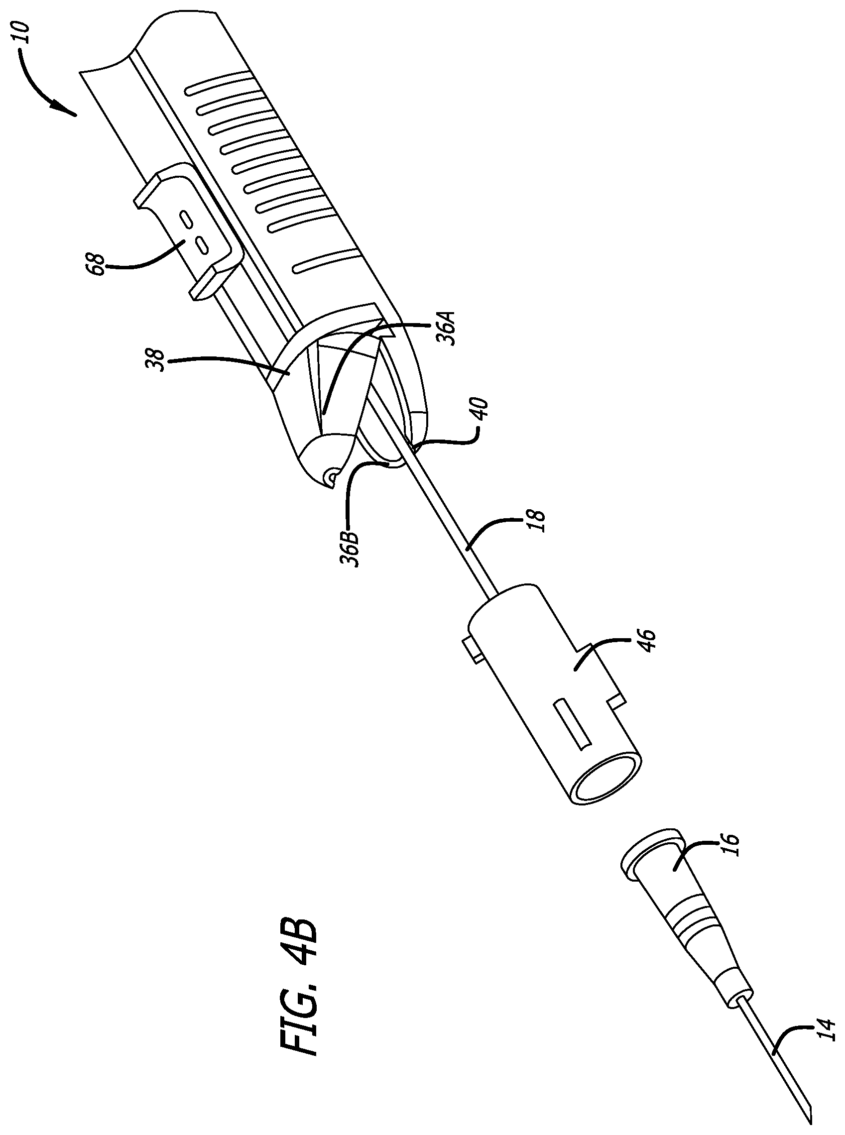
[0024] FIGS. 4A-4B show perspective exploded views of the catheter hub and safety assembly separated from the housing of a catheter insertion device, in accordance with embodiments disclosed herein.
[0025] FIG. 5A shows a cutaway side view of a catheter insertion device showing the catheter and hub in the starting position, and with the introducer needle extending from the distal end of the catheter insertion device, in accordance with embodiments disclosed herein.
[0026] FIGS. 5B-5E show various views of a catheter hub and safety assembly, in accordance with embodiments disclosed herein.
[0027] FIG. 6A shows a perspective cutaway view of a proximal portion of a catheter insertion device, in accordance with embodiments disclosed herein.
[0028] FIG. 6B shows a close up view of the catheter insertion device of FIG. 6A, in accordance with embodiments disclosed herein.
[0029] FIGS. 6C-6D show cutaway side views of the catheter insertion device of FIG. 6A, in accordance with embodiments disclosed herein.
[0030] FIG. 7A shows a perspective cutaway view of a catheter insertion device including a lockout device, in accordance with embodiments disclosed herein.
[0031] FIG. 7B shows a proximal end view of the lockout device of FIG. 7A, in accordance with embodiments disclosed herein.
[0032] FIGS. 8A-8D show various views of a catheter insertion device including a lockout device, in accordance with embodiments disclosed herein.
[0033] FIGS. 9A-9C show various views of a catheter insertion device including a lockout device, in accordance with embodiments disclosed herein.
[0034] FIGS. 10A-10D show various views of a catheter insertion device including a lockout device, in accordance with embodiments disclosed herein.
DESCRIPTION
[0035] Reference will now be made to figures wherein like structures will be provided with like reference designations. It is understood that the drawings are diagrammatic and schematic representations of exemplary embodiments of the present invention, and are neither limiting nor necessarily drawn to scale.
[0036] Regarding terms used herein, it should also be understood the terms are for the purpose of describing some particular embodiments, and the terms do not limit the scope of the concepts provided herein. Ordinal numbers (e.g., first, second, third, etc.) are generally used to distinguish or identify different features or steps in a group of features or steps, and do not supply a serial or numerical limitation. For example, "first," "second," and "third" features or steps need not necessarily appear in that order, and the particular embodiments including such features or steps need not necessarily be limited to the three features or steps. Labels such as "left," "right," "top," "bottom," "front," "back," and the like are used for convenience and are not intended to imply, for example, any particular fixed location, orientation, or direction. Instead, such labels are used to reflect, for example, relative location, orientation, or directions. Singular forms of "a," "an," and "the" include plural references unless the context clearly dictates otherwise.
[0037] For clarity it is to be understood that the word "proximal" refers to a direction relatively closer to a user using the device to be described herein, while the word "distal" refers to a direction relatively further from the user. For example, with respect to "proximal," a "proximal portion" or a "proximal end portion" of, for example, a catheter disclosed herein includes a portion of the catheter intended to be near a user when the catheter is used on a patient. Likewise, a "proximal length" of, for example, the catheter includes a length of the catheter intended to be near the user when the catheter is used on the patient. A "proximal end" of, for example, the catheter includes an end of the catheter intended to be near the user when the catheter is used on the patient. The proximal portion, the proximal end portion, or the proximal length of the catheter can include the proximal end of the catheter; however, the proximal portion, the proximal end portion, or the proximal length of the catheter need not include the proximal end of the catheter. That is, unless context suggests otherwise, the proximal portion, the proximal end portion, or the proximal length of the catheter is not a terminal portion or terminal length of the catheter.
[0038] With respect to "distal," a "distal portion" or a "distal end portion" of, for example, a catheter disclosed herein includes a portion of the catheter intended to be near or in a patient when the catheter is used on the patient. Likewise, a "distal length" of, for example, the catheter includes a length of the catheter intended to be near or in the patient when the catheter is used on the patient. A "distal end" of, for example, the catheter includes an end of the catheter intended to be near or in the patient when the catheter is used on the patient. The distal portion, the distal end portion, or the distal length of the catheter can include the distal end of the catheter; however, the distal portion, the distal end portion, or the distal length of the catheter need not include the distal end of the catheter. That is, unless context suggests otherwise, the distal portion, the distal end portion, or the distal length of the catheter is not a terminal portion or terminal length of the catheter. Also, the words "including," "has," and "having," as used herein, including the claims, shall have the same meaning as the word "comprising."
[0039] The terms "needle" and "cannula" can be used herein interchangeably to refer to a member having a sharpened or beveled end for insertion into an injection site on a subject. In one embodiment, the needle can be a thin hollow tubular member.
[0040] As used herein, and as shown in FIG. 4A, the longitudinal axis extends parallel to an axial length of the catheter, a lateral axis extends normal to the longitudinal axis, and a transverse axis extends normal to both the longitudinal and lateral axes. As used herein, the "axial" means along or parallel to the longitudinal axis of the needle and the "radial" direction is a direction perpendicular to the axial direction. The forward direction is the direction toward the distal end of the device. The backward direction is the direction toward the proximal end of the device. Unless defined otherwise, all technical and scientific terms used herein have the same meaning as commonly understood by those of ordinary skill in the art.
[0041] Embodiments disclosed herein are directed to a catheter placement device, also termed "catheter insertion device," with a streamlined operation and the ability to be placed with a single hand, allowing a user to also operate an ultrasound probe, or the like, to maintain visualization.
[0042] In reference to FIGS. 1-3, the catheter insertion device 10 generally includes a main body or housing 12, a catheter assembly, including a catheter 14 having a catheter hub 16 and a safety assembly 46, an introducer needle 18, and an actuator assembly 20. The actuator assembly 20 forms a shuttling or indexing assembly and mechanism to index and advance the catheter 14 over the end of the needle 18 in a stepwise manner by cycling through a plurality of stages. Each stage consisting of moving the actuator assembly 20 from a first position to a second position and back to the first position to advance the catheter assembly a given distance in a distal direction.
[0043] The housing 12 of the insertion device 10 has a longitudinal dimension with a distal end 22 and a proximal end 24. In an embodiment, the housing 12 can be formed from two housing halves that are joined together by a suitable attachment mechanism. For example, a first housing half and a second housing half can be aligned by one or more pins (not shown) protruding from a first housing half, which can correspond with one or more recesses 13 on a second housing half (FIG. 3). However, other configurations of pins and recesses, or similar attachment mechanisms including clips, lugs, notches, protrusions, combinations thereof, or the like are also contemplated. The housing 12 has a dimension for supporting the introducer needle 18 and catheter 14 during use and to enable the user to manipulate the device in positioning the catheter. Also shown in FIG. 3, the introducer needle 18 is hollow and has a proximal end fixed within an interior cavity 50 of the housing 12 by a post 54 or other support. The needle 18 extends from a distal end of the housing 12 through the opening 40 to a point that is distal of the distal end 22 of the housing 12.
[0044] The housing 12 can define an interior cavity 50 forming a longitudinal passage. In an embodiment, the housing 12 has curved side walls 26, a flat top wall 28 and a flat bottom wall 30. The flat bottom wall 30 is generally provided to allow the device to be placed on a flat surface in a stable position with reduced risk of falling off the surface. It will be appreciated that the shape of the device 10 can vary without limitation depending on the particular use to provide comfortable and convenient use by the operator.
[0045] In an embodiment, an elongated opening 32 is formed in the top wall 28 for receiving a portion of the actuator assembly 20 therethrough. The housing 12 can further include a tip portion ("tip") 34 having converging sides that defines the distal end 22 of the housing 12. As shown in FIG. 4A, two hinged doors 36 of tip 34 are hingedly connected to the walls 26 by a respective hinge 38. The hinged doors 36 can transition between a closed position (FIG. 1) and an open position (FIG. 4A) to access the interior cavity 50 of the housing 12 and allow removal of the catheter 14, catheter hub 16, safety assembly 46, or combinations thereof, from the housing 12. An outlet opening 40 in tip 34 enables the catheter 14 and introducer needle 18 to extend from the distal end of the housing 12 when the hinged doors 36 are in the closed configuration. The converging surfaces of tip 34 enable the device to be positioned at a low angle with respect to the skin of the patient to assist in inserting the catheter 14 and introducer needle 18 into the patient with reduced risk of kinking or folding of the catheter 14.
[0046] Further details of the catheter insertion device 10 can be found in International Patent Publication WO 2018/170349, which is incorporated by reference in its entirety into this application.
[0047] As shown in FIGS. 3-4B, in an embodiment, the actuator assembly 20 that forms the shuttling or indexing assembly, advances a catheter assembly, which includes the catheter 14, catheter hub 16, safety assembly 46, or combinations thereof, in a distal direction and in a stepwise manner through a series of stages. Each stage comprising of a back and a forward movement of the actuator assembly 20. A forward movement of the actuator assembly 20 causes an actuator tab 76 to engage a portion of the catheter assembly and urge the catheter assembly in a distal direction. At the completion of each forward stroke, the button 68 is pulled back and an adjacent tab 76 of the actuator body 66 is readied for the next forward stroke, by engaging the portion of the catheter assembly. As shown in FIG. 3, the housing can include a plurality of flexible tabs ("housing tabs") 60. Each tab of the housing tabs 60 can be configured to deflect to allow the catheter assembly, or portion thereof, to pass distally. Once the catheter assembly has advanced distally of a deflected tab 60, the tab 60 can return to the undeflected configuration. With each backward stroke, a housing tab 60 can engage the body 47 of the needle safety assembly 46 to prevent proximal movement of the catheter assembly. As shown, the starting position of the device 10 can be a retracted position (FIG. 1). However it will be appreciated that the starting position may also be an extended position (FIG. 2), the actuator assembly 20 can then be cycled through the backward and forward movement of each stage to advance the catheter assembly forward to a distal end of the housing 12.
[0048] Once the safety assembly body 47 and catheter hub 16 are advanced to a forward position, proximate a distal end 22 of housing 12, the hinged doors 36 are pivoted to the open position as shown in FIG. 4A to release catheter hub 16 and safety assembly 46, from the housing 12. In an embodiment, the doors 36 can transition to the open position by rotating through a longitudinally horizontal plane, as shown in FIG. 4A. The catheter hub 16 is advanced to contact cam surfaces 81 on the inner surface of the doors 36 to transition the doors 36 to the open position. The housing 12 can then be withdrawn proximally from catheter hub 16 to withdraw introducer needle 18 from catheter 14. The safety assembly body 47 slides over the distal end 56 of the introducer needle 18 to enclose the sharp tip and prevent an accidental needle stick injuries. The catheter hub 16 is released and separated from safety assembly 46 when the body 47 of safety assembly 46 is actuated by the withdrawing of introducer needle 18. Housing 12, with the attached introducer needle 18 and safety assembly body 47 can then be discarded. Optionally a seal forms a valve that closes a proximal end of the catheter hub 16 to control blood backflow and to allow attachment of an extension set or other devices.
[0049] As shown in FIG. 4B, in an embodiment, a first hinged door 36A can be hingedly coupled with a top wall 28 and a second hinged door 36B can be hingedly coupled with a bottom wall 30. As such, one of the first hinged door 36A or second hinged door 36B transitions to the open position by rotating through a longitudinally vertical plane, as shown in FIG. 4B. In an embodiment, a first door 36A can be hingedly coupled to the housing 12 and a second door 36B can be coupled to the housing 12 in a fixed relationship relative to the housing 12, e.g. attached thereto by adhesive, bonding, welding, etc. Advantageously, the second door 36 configured as such can provide a supporting structure for the needle 18 at the outlet opening 40 of tip 34. In an embodiment, the second door 36B is formed as integrally molded with the housing 12 to form a single structure. In an embodiment, the first door 36A can be coupled in a fixed relationship relative to the housing 12 and the second door 36B can be hinged coupled to the housing 12.
[0050] Advantageously, the hinging mechanisms of the doors 36 can simplify fabrication and/or assembly of the catheter insertion device 10 by following the bi-lateral symmetry of the device construction. For example, as shown in FIG. 4A, where the housing 12 is formed from two housing halves that are joined together along a longitudinally vertical plane, the hinged doors 36 can be coupled with the side walls 26. Similarly, as shown in FIG. 4B, where the housing 12 is formed by joining two halves along a longitudinally horizontal plane, the hinged doors 36 can be coupled with the top and bottom walls 28, 30 to facilitate fabrication and assembly.
[0051] As shown in FIGS. 5A-5E, in an embodiment, the housing 12 includes a plurality of rigid abutments ("housing abutments") 260. Further, the actuator body 66 includes a plurality of rigid abutments ("actuator abutments") 276. As shown in FIGS. 5B-5E, the catheter assembly can include one or more indexing fingers 264. The indexing finger 264 can extend from a side wall of the safety assembly body 47 and can be angled towards a proximal end. The indexing finger 264 can be configured to elastically deflect inward towards a central axis, and can be biased to an outward position as shown in FIGS. 5B-5E.
[0052] In an embodiment, the safety assembly body 47 includes a first indexing finger 264A extending from a first side of the body 47 and a second indexing finger 264B extending from a second side of the body 47. In an embodiment, the first and second sides are opposite each other, although other configurations are contemplated. The first indexing finger 264A extends towards the actuator abutments 276 of the actuator body 66, and the second indexing finger 264B extends toward the housing abutments 260 of the housing 12.
[0053] In use, the button 68 of the actuator assembly 20 is initially in the retracted position as shown in FIG. 5A, and the user can slide the button 68 forward to a second, extended position. An abutment 276 disposed toward the proximal end of the actuator body 66 engages the first indexing finger 264A disposed on an upper surface of the safety body 47 and slides the catheter assembly forward a distance corresponding to the distance of travel of the actuator button 68. The housing abutments 260 on the bottom wall 30 of the housing 12 are positioned to complement the spacing and location of the actuator abutments 276.
[0054] The forward movement of the safety body 47 toward the distal end 22 of the housing 12 causes the second indexing finger 264B to deflect until a proximal end thereof travels distally of a housing abutment 260. The indexing finger 264B, which is biased outwardly, then engages the housing abutment 260 to retain the body 47 in the advanced position and prevent the body 47 from sliding back toward the proximal end 24 of the housing 12. The advancing movement of the body 47 advances the catheter forward over the fixed introducer needle 18.
[0055] The button 68 can then slide backward toward the retracted position where the first indexing finger 264A deflects and slides over an adjacent actuator abutment 276 to engage a distally facing contact point thereon. Thus completing a stage cycle that advances the catheter assembly by a step of the stepwise advancement. The button 68 can then slide forward again to repeat the cycle where the first indexing finger 264A and the second indexing finger 264B can engage consecutive actuator abutments 276 and housing abutments 260 to advance the catheter 14 in a stepwise manner.
[0056] In an embodiment, the button 68 can slide between the retracted position and the extended position by manual manipulation by the user. In an embodiment, the catheter insertion device 10 can include a one or more biasing members, e.g. a spring, to transition the button 68 and actuator assembly between the retracted position and the extending position. For example, from the extended position to the retracted position, or from the retracted position to the extended position. Advantageously, the biasing member can facilitate one-handed use of the catheter insertion device 10 by automatically resetting the actuator assembly to one of the retracted or extended positions, ready for manual manipulation of the actuator assembly 20 in a subsequent step.
[0057] In an embodiment, as shown in FIGS. 5B-5C, the indexing fingers 264 are integrally molded with the safety body 47 to form a single structure. In an embodiment, as shown in FIGS. 5C-5D, the indexing fingers 264 are formed as a separate structure from that of the safety body 47 and coupled thereto. In an embodiment, the indexing finger 264 can be formed from the same material as the safety body 47 or from a different material. Exemplary materials include plastic, polymers, metals, alloys, or any suitably resilient material. As shown in FIGS. 5C-D, the indexing fingers 264 extend from a collar 266. The collar 266 can extend at least partially around a portion of the safety assembly body 47. In an embodiment, the collar 266 extends from a first side to a second side of the safety assembly body 47. In an embodiment the collar 266 encircles the safety assembly body 47 to surround the longitudinal axis of the body 47. In an embodiment, the safety body 47 includes one or more recesses configured to retain a portion of the collar 266, indexing finger 264, or combinations thereof, to further secure the collar 266/indexing fingers 264 thereto.
[0058] Advantageously, the catheter insertion device 10 including rigid actuator abutments 276, housing abutments 260, and flexible indexing fingers 264 requires less moving parts. This simplifies manufacture and assembly of the catheter insertion device 10 as well as providing a more robust operation of the catheter insertion device 10. Further, by forming the indexing fingers as part of the safety body 47, the manufacture and assembly of the catheter insertion device 10 is further simplified. In the alternative that the indexing fingers are formed as a separate structure, and optionally of a separate material, the amount of spring forces or resistance to deflection, can be more accurately defined or modified. This allows the catheter insertion device 10 to balance the actuator button 68 and catheter advancement forces.
[0059] As shown in FIGS. 6A-6D, in an embodiment, the catheter insertion device 10 can include a combination of flexible housing tabs 60 and rigid actuator abutments 276. Other combinations are also contemplated for example rigid housing abutments 260 and flexible actuator tabs 76. As described herein, the catheter insertion device 10 includes a housing 12 and an actuator assembly 20 that includes a button 68 coupled to an actuator body 66. The actuator body 66 extends proximally, substantially to a proximal end of the housing 12, and includes a top wall 228, a first side wall 226A, and a second side wall 226B. The top wall 228 extends below the top wall 28 of the housing 12 and above the catheter assembly, which includes the catheter 14, catheter hub 16, and safety assembly 46. The first side wall 226A, and the second side wall 226B extend from the top wall 228, inside of the side walls 26 of the housing 12, and outside of the catheter assembly. The top wall 228, first side wall 226A, and second side wall 226B can create an inverse channel within which the catheter assembly can travel along a longitudinal axis. Optionally, the actuator body 66 can include a rounded or chamfered portion to fit snuggly within the interior cavity 50 of the housing 12.
[0060] In an embodiment, one of the first side wall 226A and the second side wall 226B can include a plurality of notches 274 extending upwards from a lower edge of the side wall to define an abutment surface 276 on a distally facing surface of the notch 274. As shown, the notches 274 define a substantially rectangular shape when viewed from a side profile, however it will be appreciated that notches 274 can also define other shapes, such as triangular or semi-circular, and still remain within the scope of the present invention. In an embodiment, the side walls 226A, 226B can include a plurality of apertures disposed therein to define the distally facing abutment surfaces 276.
[0061] FIG. 6B shows a close up view of the proximal end of the catheter insertion device 10 shown in FIG. 6A. As shown, the safety assembly body 47 includes a collar 266 that supports the first indexing finger 264A and the second indexing finger 264B. In an embodiment, the indexing fingers 264A, 264B can also be formed as a single piece with the safety body 47, as described herein. The collar 266 engages a portion of the safety body 47 and supports the indexing fingers 264A, 264B in an outwardly biased position. The first indexing finger 264A extends from a first side portion of the safety body 47, and the second indexing finger 264B extends from a second side portion of the safety body 47, opposite the first side portion. The indexing fingers 264A, 264B are aligned with the plurality of notches 274 so that a proximal tip of the indexing fingers 264 engage a distally facing abutment surface 276. The housing 12 further includes a plurality of housing tabs 60 that engage a lower portion of the safety body 47 to prevent proximal movement thereof, as described herein.
[0062] In use, the catheter insertion device 10 includes an actuator button 68 disposed in the retracted, starting position, for example, as shown in FIG. 5A. A user can manipulate the actuator button 68 to move the actuator assembly 20 in a distal direction from the starting position, to an extended position (FIG. 6C). As shown in FIG. 6C, a proximal abutment surface 276, of the first side wall 226A engages the first indexing fingers 264A, and a proximal abutment surface 276, e.g. a first abutment surface 276a, of the second side wall 226B engages the second indexing finger 264B. Advancing the actuator assembly 20 to the extended position distally advances the catheter assembly. The catheter assembly is advanced distally of a proximal tab 60. The tab 60 deflects downwards to allow the catheter assembly to pass, before returning to the undeflected position to engage surface 64 on the safety assembly 46. This prevents proximal movement of the catheter assembly.
[0063] As shown in FIG. 6D, the actuator assembly 20 is then moved proximally, from the extended position to the retracted, starting position. As the actuator body 66 moves proximally, the first indexing finger 264A and the second indexing finger 264B deflect to allow a portion of the side walls 226A, 226B to pass until an adjacent notch 274 aligns with the indexing fingers 264A, 264B allowing the indexing fingers to engage an adjacent abutment surface 276, e.g. a second abutment surface 276b. The cycle then repeats to advance the catheter assembly distally in a stepwise manner.
[0064] Advantageously, embodiments including the actuator body 66 defining an inverse channel require relatively less moving parts to facilitate manufacture and assembly. Further, the actuator body 66 provides a channel within which the catheter assembly can travel. The device 10 also provides dual contact points between the actuator assembly 20 and the safety assembly 46 that are disposed evenly about a central axis. These features provide an even application of force and prevents the catheter assembly, or portions thereof, from pivoting relative to the longitudinal axis during distal advancement. This prevents the indexing mechanism from jamming and provides a more robust operation.
[0065] In an embodiment, the catheter insertion device 10 can include a lockout device. As described in more detail herein, the lockout device can include one of a button, collar, slider or tab. In general, the lockout device can selectively restrict the stepwise advancement mechanism to inhibit the catheter insertion device 10 from advancing beyond an initial stage, while still allowing some movement of the catheter 14 relative to the needle 18. This allows a user to break any adhesion between the catheter 14 and the needle 18 that may have occurred during manufacture, prior to deployment of the catheter 14. The user can then selectively unlock the lockout device to allow the catheter insertion device 10 to cycle through a first stage. Breaking the adhesion ensures a smooth, uniform advancement through each stage of the stepwise advancement.
[0066] As shown in FIGS. 7A-7B, in an embodiment, the catheter insertion device 10 includes a lockout button 240 that includes an actuator surface 242 coupled with an engagement arm 244, and can transition between a locked position (e.g. FIG. 7A) and an unlocked position. The engagement surface 244 includes a first, substantially circular aperture 246 defining a first diameter (x) and a second, substantially circular aperture 248 defining a second diameter (y). As shown in FIG. 7B, the first aperture 246 and second aperture 248 can communicate to define a "keyhole" shaped aperture. As shown in FIG. 7A, the safety assembly body 47 includes a cylindrical anchor portion 250, extending proximally therefrom, and defining a substantially circular cross-section. The cross-section of the anchor 250 defines a diameter that is the same or less than the diameter (x) of the first aperture 246. The anchor 250 also includes a flange 252 extending radially from a proximal end of the anchor portion 250. The flange 252 defines a diameter that is larger than the diameter (x) of the first aperture 246 but smaller than the diameter (y) of the second aperture 248.
[0067] As shown in FIG. 7A, the lockout button 240 is deployed in the locked position where the anchor 250 is disposed within the first aperture 246 and the flange 252 abuts against the engagement arm 244. In this position the longitudinal movement of the safety assembly 46, as well as catheter 14 and catheter hub 16, are restricted.
[0068] In an embodiment, the longitudinal movement of the safety assembly 46 is restricted to a distance that is less than the longitudinal distance between adjacent housing abutments 260, adjacent actuator abutments 276, adjacent housing tabs 60, or adjacent actuator tabs 76. In an embodiment, the longitudinal movement of the safety assembly 46 is restricted to a distance that is substantially half the longitudinal distance between adjacent housing abutments 260, adjacent actuator abutments 276, adjacent housing tabs 60, or adjacent actuator tabs 76. In an embodiment, the longitudinal movement of the safety assembly 46 is restricted to a longitudinal distance of between 1 mm to 3 mm, however greater or lesser distances are also contemplated.
[0069] With the lockout button 240 in the locked position a user is able to move the actuator assembly 20 so as to move the catheter 14 relative to the needle 18, but is not able to move the catheter assembly 20 beyond a first step of the stepwise advancement, i.e. not as far as the next tab 60, or abutment 260. This movement breaks loose any adhesion between the catheter 14 and the needle 18 that may have formed during manufacture, assembly, transport or storage. When the user is ready to advance the catheter, the lockout button 240 can be transitioned to the unlocked position, where the anchor 250 is disposed within the second aperture 248 and the flange 252 can pass through the aperture 248. This allows the actuator assembly 20 to advance the catheter assembly in a stepwise manner, as described herein. It will be appreciated that the configuration and location of the lockout button 240 and apertures 246, 248 can vary from that shown in FIGS. 7A-7B without departing from the spirit of the invention. For example, the orientation of the apertures 246, 248 can be reversed so that the unlocked position of the lockout button 240 is an extended position and a locked position is a retracted position. Similarly, the location of the button 240 can extend from a lower, upper, or side surface of the housing 12.
[0070] Advantageously, the lockout button 240 allows the user to break loose any adhesion between the catheter 14 and the needle 18 that may have formed during assembly, transport or storage. This loosens the movement between the catheter 14 and the needle 18 prior to use and ensures a smooth, uniform and controlled action when the catheter 14 is deployed.
[0071] As shown in FIGS. 8A-8D, in an embodiment, the catheter insertion device 10 includes a lockout collar 280 that restricts movement of the actuator button 68, the actuator assembly, and the catheter assembly engaged therewith. The lockout collar 280 is disposed on an outer surface of the housing 12 and encircles the housing 12 about the longitudinal axis. In an embodiment, the collar 280 encircles a portion of the housing 12 such that it can be detached from the catheter insertion device 10 by sliding the collar 280 perpendicular to the longitudinal axis. The housing 12 includes one or more protrusions, for example a first protrusion 282 and a second protrusion 284, extending from an outer surface thereof. The lockout collar 280 can slide relative to the first protrusion 282 and a second protrusion 284 to transition between a locked position and an unlocked position.
[0072] As shown in FIGS. 8A-8B, the lockout collar 280 can be disposed in a locked position where the collar 280 is disposed between the first protrusion 282 and the actuator button 68 so as to cover at least a portion of the opening 32. In the locked position, the longitudinal movement of the actuator assembly 20, and the catheter assembly engaged therewith, is restricted.
[0073] In an embodiment, the longitudinal movement of the actuator assembly 20 is restricted to a distance that is less than the length of the opening 32. In an embodiment, the longitudinal movement of the actuator assembly 20 is restricted to a distance that is substantially half of the length of the opening 32. In an embodiment, the longitudinal movement of the actuator assembly 20 is restricted to a distance that is less than the longitudinal distance between adjacent housing abutments 260, adjacent actuator abutments 276, adjacent housing tabs 60, or adjacent actuator tabs 76. In an embodiment, the longitudinal movement of the actuator assembly 20 is restricted to a distance that is substantially half of the longitudinal distance between adjacent housing abutments 260, adjacent actuator abutments 276, adjacent housing tabs 60, or adjacent actuator tabs 76. In an embodiment, the longitudinal movement of the actuator assembly 20 is restricted to a distance of between about 1 mm to about 3 mm, however greater or lesser distances are also contemplated.
[0074] With the lockout collar 280 in the locked position, a user is able to move the actuator assembly 20 so as to move the catheter 14 relative to the needle 18, but is not able to move the catheter assembly beyond a first step of the stepwise advancement, i.e. not as far as the next housing tab 60, or housing abutment 260. This movement breaks loose any adhesion between the catheter 14 and the needle 18 that may have formed during assembly, transport or storage. When the user is ready to advance the catheter 14, the lockout collar 280 can be removed, or slid to the unlocked position, i.e. between the first protrusion 282 and the second protrusion 284 where the collar 280 does not cover the opening 32. This allows the actuator assembly 20 to advance the catheter assembly in a stepwise manner, as described herein.
[0075] In an embodiment, the first protrusion 282 is disposed at one of a distal end or a proximal end of the opening 32 and configured to restrict movement of the collar 280 relative to the housing along a longitudinal axis to maintain the lockout collar 280 in the locked position. When ready for use, the user can slide the lockout collar 280 over the first protrusion 282 to the "unlocked" position. In an embodiment, the collar 280 further includes a skive 286 on an inner surface of the collar 280 to facilitate moving the lockout collar 280 over the first protrusion 282.
[0076] The second protrusion 284 can be positioned a distance from the first protrusion 282 so that the lockout collar 280 can be received therebetween. In an embodiment, the first protrusion 282 and the second protrusion 284 protrude a similar height from the outer surface of the housing 12. Optionally, the lockout collar 280 can be slid past the second protrusion 284 and be removed from the catheter insertion device 10. In an embodiment, the second protrusion 284 protrudes further from the outer surface of the housing 12 than the first protrusion 282, and prevents the lockout collar 280 from being removed from the catheter insertion device 10. Optionally, the lockout collar 280 includes a contrasting color, tactile features, gripping features, alphanumeric symbols, icons, or combinations thereof, to distinguish the lockout collar 280 from that of the housing 12 and notify the user that the catheter insertion device 10 is in the locked or unlocked position.
[0077] As shown in FIGS. 8A-8D, the lockout collar 280, first protrusion 282, and second protrusion 284 are disposed between the actuator button 68 and a proximal end of the catheter insertion device 10 such that the collar 280 is slid in a proximal direction to the "unlocked" position. It will be appreciated, however, that the orientation of the actuator button 68, lockout collar 280, first protrusion 282, and second protrusion 284 can be disposed in other configurations without departing from the spirit of the invention. For example, the collar 280 can be slid in a distal direction to move from the locked position to the unlocked position and optionally be removed from the catheter insertion device 10.
[0078] As shown in FIGS. 9A-9C, in an embodiment, the catheter insertion device 10 can include a lockout slider 270 that can transition between a locked position, to restrict the movement of the actuator button 68 (FIG. 9A), and an unlocked position to allow the actuator assembly to move along the elongate opening 32 (FIG. 9C). In an embodiment, the lockout slider 270 can be slid perpendicular to the longitudinal axis, i.e. the direction of travel of the actuator assembly 20, to engage notch 268. However, it will be appreciated that other orientations of slider 270 and notch 268 are also contemplated.
[0079] A longitudinal width of the slider 270 can define a first width (a). A longitudinal width of the notch 268 can define a second width (b). In an embodiment, the width of the slide (a) is less than a width of the notch (b). The notch 268 can engage the slider 270 to restrict the movement of the actuator assembly 20. As shown in FIG. 9A, the lockout slider 270 is deployed in the locked position where the slider 270 engages notch 268. In this position the longitudinal movement of the safety actuator assembly 20 and the catheter assembly engaged therewith, are restricted.
[0080] In an embodiment, the longitudinal movement of the actuator assembly 20 is restricted to a distance that is less than the length of the opening 32. In an embodiment, the longitudinal movement of the actuator assembly 20 is restricted to a distance that is substantially half of the length of the opening 32. In an embodiment, the longitudinal movement of the actuator assembly 20 is restricted to a distance that is less than the longitudinal distance between adjacent housing abutments 260, adjacent actuator abutments 276, adjacent housing tabs 60, or adjacent actuator tabs 76. In an embodiment, the longitudinal movement of the actuator assembly 20 is restricted to a distance that is substantially half of the longitudinal distance between adjacent housing abutments 260, adjacent actuator abutments 276, adjacent housing tabs 60, or adjacent actuator tabs 76. In an embodiment, the longitudinal movement of the actuator assembly 20 is restricted to a distance of between about 1 mm to about 3 mm, however greater or lesser distances are also contemplated.
[0081] With the lockout slider 270 in the locked position a user is able to move the actuator assembly 20 so as to move the catheter 14 relative to the needle 18, but is not able to move the catheter assembly beyond a first step of the stepwise advancement, i.e. not as far as the next housing tab 60, or housing abutment 260. This movement breaks loose any adhesion between the catheter 14 and the needle 18 that may have formed during assembly, transport or storage. When the user is ready to advance the catheter, the lockout slider 270 can be moved to the unlocked position, where the actuator assembly 20 can advance the catheter assembly in a stepwise manner, as described herein.
[0082] FIGS. 10A-10D show an embodiment of the catheter insertion device 10 including a lockout tab 290. FIG. 10A shows a plan view of the catheter insertion device 10 and FIG. 10B shows a cutaway side view of the catheter insertion device 10 with the lockout tab 290 in the "locked" position, i.e. disposed within guide slot 77 of housing 12. To note, a proximal end 74 of the actuator body 66 includes a guide pin 75 that is received within slot 77 to stabilize the proximal end 74 of the actuator body 66. Further details of which can be found in WO 2018/170349, which is incorporated by reference in its entirety herein.
[0083] FIG. 10C shows a cutaway plan view of the catheter insertion device 10 and FIG. 10D shows a cutaway side view of the catheter insertion device 10 with the lockout tab 290 in the "unlocked" position, i.e. removed from slot 77. In an embodiment, the catheter insertion device 10 includes a first slot 77A disposed on a first of the housing 12 and a second slot 77B disposed on a second side of the housing 12, opposite the first side. In an embodiment, the lockout tab 290 can be disposed through either of the first slot 77A or the second slot 77B. In an embodiment, the lockout tab 290 can be disposed through both of the first and second slots 77A, 77B.
[0084] As shown in FIG. 10B, in the "locked" position, the lockout tab 290 is disposed between a proximal end of the actuator assembly 20 and an inner surface of the housing 12, i.e. between the guide pin 75 and a proximal edge of the slot 77, to restrict movement of the actuator assembly 20, and catheter 14. The longitudinal width (t) of the lockout tab 290 can be less than the longitudinal length of the slots 77A, 77B, and can be modified to vary the amount of restriction imposed on the actuator assembly 20.
[0085] In an embodiment, the longitudinal movement of the actuator assembly 20 is restricted to a distance that is less than the longitudinal length of the first slot 77A or the second slot 77B. In an embodiment, the longitudinal movement of the actuator assembly 20 is restricted to a distance that is substantially half of the longitudinal length of the first slot 77A or the second slot 77B. In an embodiment, the longitudinal movement of the actuator assembly 20 is restricted to a distance that is less than the longitudinal distance between adjacent housing abutments 260, adjacent actuator abutments 276, adjacent housing tabs 60, or adjacent actuator tabs 76. In an embodiment, the longitudinal movement of the actuator assembly 20 is restricted to a distance that is substantially half of the longitudinal distance between adjacent housing abutments 260, adjacent actuator abutments 276, adjacent housing tabs 60, or adjacent actuator tabs 76. In an embodiment, the longitudinal movement of the actuator assembly 20 is restricted to a distance of between about 1 mm to about 3 mm, however greater or lesser distances are also contemplated.
[0086] With the lockout button 240 in the locked position a user is able to move the actuator assembly 20 so as to move the catheter 14 relative to the needle 18, but is not able to move the catheter assembly beyond a first step of the stepwise advancement, i.e. not as far as the next tab 60, or abutment 260. This movement breaks loose any adhesion between the catheter 14 and the needle 18 that may have formed during manufacture, assembly, transport or storage. When the user is ready to advance the catheter, the lockout tab 290 can be removed. This allows the actuator assembly 20 to advance the catheter assembly in a stepwise manner, as described herein. Optionally, the lockout device, e.g. the lockout tab 290, can include a contrasting color, tactile features, gripping features, alphanumeric symbols, icons, or combinations thereof, to distinguish the lockout tab 290 from that of the housing 12 and notify the user that the catheter insertion device 10 is in the locked or unlocked position.
[0087] While some particular embodiments have been disclosed herein, and while the particular embodiments have been disclosed in some detail, it is not the intention for the particular embodiments to limit the scope of the concepts provided herein. Additional adaptations and/or modifications can appear to those of ordinary skill in the art, and, in broader aspects, these adaptations and/or modifications are encompassed as well. Accordingly, departures may be made from the particular embodiments disclosed herein without departing from the scope of the concepts provided herein.
* * * * *
D00000
D00001
D00002
D00003
D00004
D00005
D00006
D00007
D00008
D00009
D00010
D00011
D00012

D00013

D00014

XML
uspto.report is an independent third-party trademark research tool that is not affiliated, endorsed, or sponsored by the United States Patent and Trademark Office (USPTO) or any other governmental organization. The information provided by uspto.report is based on publicly available data at the time of writing and is intended for informational purposes only.
While we strive to provide accurate and up-to-date information, we do not guarantee the accuracy, completeness, reliability, or suitability of the information displayed on this site. The use of this site is at your own risk. Any reliance you place on such information is therefore strictly at your own risk.
All official trademark data, including owner information, should be verified by visiting the official USPTO website at www.uspto.gov. This site is not intended to replace professional legal advice and should not be used as a substitute for consulting with a legal professional who is knowledgeable about trademark law.