Multiple Suture Threader And Methods Of Use
PHISITKUL; Phinit ; et al.
U.S. patent application number 17/094566 was filed with the patent office on 2021-02-25 for multiple suture threader and methods of use. This patent application is currently assigned to Crossroads Extremity Systems, LLC. The applicant listed for this patent is Crossroads Extremity Systems, LLC. Invention is credited to T. Wade FALLIN, Phinit PHISITKUL, Justin TABER.
| Application Number | 20210052267 17/094566 |
| Document ID | / |
| Family ID | 1000005207429 |
| Filed Date | 2021-02-25 |
| United States Patent Application | 20210052267 |
| Kind Code | A1 |
| PHISITKUL; Phinit ; et al. | February 25, 2021 |
MULTIPLE SUTURE THREADER AND METHODS OF USE
Abstract
The disclosure provides apparatus and methods of use pertaining to a multiple suture threader. Embodiments of the multiple suture threader include a handle that is coupled with a first collapsible loop and a second collapsible loop that is axially offset from the first collapsible loop. In use, one or more sutures are doubled over each of the first and the second collapsible loops such that when the axially spaced loops are passed through a narrow axial passage of a surgical implant, a surgical instrument, or a bodily passage such as a bone tunnel, a twenty-five to fifty percent reduction in suture traffic, or in the maximum number of suture thicknesses that simultaneously pass through the narrow passage, is achieved. Other embodiments are disclosed.
| Inventors: | PHISITKUL; Phinit; (Dakota Dunes, SD) ; TABER; Justin; (Honolulu, HI) ; FALLIN; T. Wade; (Hyde Park, UT) | ||||||||||
| Applicant: |
|
||||||||||
|---|---|---|---|---|---|---|---|---|---|---|---|
| Assignee: | Crossroads Extremity Systems,
LLC Memphis TN |
||||||||||
| Family ID: | 1000005207429 | ||||||||||
| Appl. No.: | 17/094566 | ||||||||||
| Filed: | November 10, 2020 |
Related U.S. Patent Documents
| Application Number | Filing Date | Patent Number | ||
|---|---|---|---|---|
| 15641618 | Jul 5, 2017 | 10842480 | ||
| 17094566 | ||||
| 62458975 | Feb 14, 2017 | |||
| 62456217 | Feb 8, 2017 | |||
| 62425560 | Nov 22, 2016 | |||
| 62358231 | Jul 5, 2016 | |||
| Current U.S. Class: | 1/1 |
| Current CPC Class: | A61B 17/06166 20130101; A61B 17/1604 20130101; A61B 17/848 20130101; A61B 90/06 20160201; A61B 2017/0464 20130101; A61B 17/8869 20130101; A61B 17/80 20130101; A61B 2017/044 20130101; A61B 2017/0453 20130101; A61B 2017/045 20130101; A61B 2017/0445 20130101; A61B 17/0485 20130101; A61B 2017/0403 20130101; A61B 2017/0441 20130101; A61B 2017/0414 20130101; A61B 17/885 20130101; A61B 17/0401 20130101; A61B 2017/0409 20130101; A61B 2017/00526 20130101; A61B 2017/0404 20130101; A61B 2017/00867 20130101; A61B 2090/061 20160201 |
| International Class: | A61B 17/04 20060101 A61B017/04; A61B 17/06 20060101 A61B017/06; A61B 17/16 20060101 A61B017/16; A61B 90/00 20060101 A61B090/00; A61B 17/88 20060101 A61B017/88 |
Claims
1. A suture threader for passing at least first and second sutures, each having first and second opposing ends, through a passage having a proximal opening and a distal opening in a manner that reduces suture traffic through the passage, the suture threader comprising: a handle; a first collapsible loop suspended from the handle at a first distal offset, the first collapsible loop configured to receive the first end of the first suture doubled over the first collapsible loop; and a second collapsible loop suspended from the handle at a second distal offset from the first collapsible loop, the second collapsible loop configured to receive the first end of the second suture doubled over the second collapsible loop, wherein when the first and the second collapsible loops are passed through the passage to draw the first and the second sutures through the passage such that the first ends of the first and the second sutures are located proximal to the proximal opening of the passage and the second ends of the first and the second sutures are located distal to the distal opening of the passage, a total number of suture thicknesses to pass simultaneously through the passage is limited to three.
2. The suture threader of claim 1, wherein the first collapsible loop is formed from a first filament attached to the handle, and the second collapsible loop is formed from a second filament attached to the handle.
3. The suture threader of claim 2, wherein the first and the second filaments forming the first and the second collapsible loops may be formed of a flexible wire or a polymer strand.
4. The suture threader of claim 1, wherein the first and the second collapsible loops are formed from a common filament suspended from the handle.
5. The suture threader of claim 4, wherein the common filament forming the first and the second collapsible loops is formed of a flexible wire or a polymer strand.
6. The suture threader of claim 4, wherein a distal base of the first collapsible loop is formed via one of crossing the common filament over itself, laser welding, adhesive bonding, diffusion bonding, crimping, ultrasonic welding, radio frequency welding, and melt bonding.
7. The suture threader of claim 1, further comprising a third collapsible loop suspended from the handle at a third distal offset from the second collapsible loop, the third collapsible loop configured to receive a third suture having opposing first and second ends, the first end of the third suture doubled over the third collapsible loop, wherein when the first, the second, and the third collapsible loops are passed through the passage to draw the first, the second, and the third sutures through the passage such that the first ends of the first, the second, and the third sutures are located proximal to the proximal opening of the passage and the second ends of the first, the second, and the third sutures are located distal to the distal opening of the passage, the total number of suture thicknesses to pass simultaneously through the passage is limited to four.
8. The suture threader of claim 1, wherein: the first collapsible loop is further configured to receive a third suture having opposing first and second ends, the first end of the third suture doubled over the first collapsible loop; and the second collapsible is further configured to receive a fourth suture having opposing first and second ends, the first end of the fourth suture doubled over the second collapsible loop, wherein when the first and the second collapsible loops are passed through the passage to draw the first, the second, the third, and the fourth sutures through the passage such that the first ends of the first, the second, the third, and the fourth sutures are located proximal to the proximal opening of the passage and the second ends of the first, the second, the third, and the fourth sutures are located distal to the distal opening of the passage, a total number of suture thicknesses to pass simultaneously through the passage is limited to six.
9. The suture threader of claim 1, wherein the passage forms a pathway through a cannula of a surgical instrument, a sheath of a surgical implant, a bodily lumen, or a bone tunnel.
10. A method of threading multiple sutures through an axial passage, comprising: providing a suture threader having a proximal end and a distal end, a first collapsible loop located at a first distal offset from the proximal end, and a second collapsible loop located at a second distal offset from the first collapsible loop; passing the first and the second collapsible loops of the suture threader through the axial passage such that the axial passage is positioned along the first distal offset; threading one or more first threads through the first collapsible loop such that a first end of each of the one or more of the first threads is doubled over the first collapsible loop; threading one or more second threads through the second collapsible loop such that a first end of each of the one or more of the second threads is doubled over the second collapsible loop; pulling the first collapsible loop through the axial passage until each of the first ends of the one or more of the first sutures exits a proximal end of the axial passage; and pulling the second collapsible loop through the axial passage until each of the first ends of the one or more of the second sutures exits the proximal end of the axial passage, wherein a maximum number of suture thicknesses to simultaneously pass through the axial passage equals one thickness for each of the one or more of the first threads plus two thicknesses for each of the one or more of the second threads.
11. The method of claim 10, wherein the suture threader further includes a handle attached at the proximal end of the threader.
12. The method of claim 11, wherein the first flexible loop is suspended from the handle via a first filament and the second flexible loop is suspended from the handle via a second filament.
13. The method of claim 11, wherein the first and the second flexible loops are suspended from the handle via a common filament.
14. The method of claim 13, wherein a distal base of the first collapsible loop is formed via one of crossing the common filament over itself, laser welding, adhesive bonding, diffusion bonding, crimping, ultrasonic welding, radio frequency welding, and melt bonding.
15. The method of claim 10, wherein the first and the second collapsible loops are formed of flexible wire or polymer strand.
16. A method of reducing suture traffic through an axial passage using a suture threader having a handle located at a proximal end of the suture threader, a first collapsible loop located at a first distal offset from the handle, and a second collapsible loop located at a second distal offset from the first collapsible loop, the method comprising: passing the first and the second collapsible loops of the suture threader through the axial passage such that the handle is located proximal to the axial passage and the first and the second collapsible loops are located distal to the axial passage; providing at least a first suture and a second suture, each of the first and the second sutures having first and second opposing ends; doubling the first end of the first suture over the first collapsible loop to form first and second thicknesses at the first end of the first suture; doubling the first end of the second suture over the second collapsible loop to form first and second thicknesses at the first end of the second suture; first pulling the first collapsible loop through the axial passage such that when the first end of the first suture passes through the axial passage, the first and the second thicknesses of the first suture are located within the axial passage, and when the first end of the first suture exits the axial passage, the second thickness of the first suture remains within the axial passage; and second pulling the second collapsible loop through the axial passage such that when the first end of the second suture passes through the axial passage, the second thickness of the first suture and the first and the second thicknesses of the second suture are located within the axial passage, and when the first end of the second suture exits the axial passage, the second thickness of the first suture and the second thickness of the second suture remain within the axial passage.
17. The method of claim 16, wherein the first and the second collapsible loops are formed from a common wire suspended from the handle.
18. The method of claim 17, wherein a distal base of the first collapsible loop is formed via one of crossing the common wire over itself, laser welding, adhesive bonding, diffusion bonding, and crimping.
19. The method of claim 16, wherein the first and the second collapsible loops are formed of flexible wire or polymer strand.
20. The method of claim 16, wherein the axial passage forms a pathway through a cannula of a surgical instrument, a sheath of a surgical implant, a bodily lumen, or a bone tunnel.
Description
CROSS-REFERENCE TO RELATED APPLICATIONS
[0001] This application is a continuation of U.S. patent application Ser. No. 15/641,618 filed on Jul. 5, 2017, entitled MULTIPLE SUTURE THREADER AND METHODS OF USE, which claims the benefit under 35 U.S.C. 119(e) of U.S. Provisional Application No. 62/358,231, filed on Jul. 5, 2016, entitled LIGAMENT REINFORCEMENT DEVICES AND METHODS, 62/425,560 filed on Nov. 22, 2016, entitled LIGAMENT REINFORCEMENT DEVICES AND METHODS, 62/456,217, filed on Feb. 8, 2017, entitled PLATE AND LOOP CONSTRUCT, and 62/458,975, filed on Feb. 14, 2017 entitled PELVIC FRACTURE REPAIR, all of which patent applications are hereby incorporated herein by reference.
BACKGROUND
[0002] Suture threaders or suture passers are devices used to pass a suture through material passages such as, for example, bodily tissue passages/lumen of a surgical patient, surgical implants such as fixation or anchor hardware, or cannulas formed within surgical instruments. Oftentimes sutures must be passed or threaded through a narrow passage through a patient's bone tunnel or arterial or intestinal lumen, or through a cannula or sleeve incorporated within a surgical instrument or another piece of surgical hardware. When a loop-style suture threader is employed, the sutures are doubled over the loop, which creates excess bulk that cannot easily be passed through the narrow passage.
SUMMARY
[0003] This Summary is provided to introduce a selection of concepts in a simplified form that are further described below in the Detailed Description. This Summary is not intended to identify key aspects or essential aspects of the claimed subject matter. Moreover, this Summary is not intended for use as an aid in determining the scope of the claimed subject matter.
[0004] One embodiment provides a suture threader for passing at least first and second sutures, each having first and second opposing ends, through a passage having a proximal opening and a distal opening in a manner that reduces suture traffic through the passage. The suture threader includes (1) a handle; (2) a first collapsible loop suspended from the handle at a first distal offset, the first collapsible loop configured to receive the first end of the first suture doubled over the first collapsible loop; and (3) a second collapsible loop suspended from the handle at a second distal offset from the first collapsible loop. The second collapsible loop is configured to receive the first end of the second suture doubled over the second collapsible loop, wherein when the first and the second collapsible loops are passed through the passage to draw the first and the second sutures through the passage such that the first ends of the first and the second sutures are located proximal to the proximal opening of the passage and the second ends of the first and the second sutures are located distal to the distal opening of the passage, a total number of suture thicknesses to pass simultaneously through the passage is limited to three.
[0005] Another embodiment provides a method of threading multiple sutures through an axial passage. The method includes the steps of (1) providing a suture threader having a proximal end and a distal end, a first collapsible loop located at a first distal offset from the proximal end, and a second collapsible loop located at a second distal offset from the first collapsible loop; (2) passing the first and the second collapsible loops of the suture threader through the axial passage such that the axial passage is positioned along the first distal offset; (3) threading one or more first threads through the first collapsible loop such that a first end of each of the one or more of the first threads is doubled over the first collapsible loop; (4) threading one or more second threads through the second collapsible loop such that a first end of each of the one or more of the second threads is doubled over the second collapsible loop; (5) pulling the first collapsible loop through the axial passage until each of the first ends of the one or more of the first sutures exits a proximal end of the axial passage; and (6) pulling the second collapsible loop through the axial passage until each of the first ends of the one or more of the second sutures exits the proximal end of the axial passage, wherein a maximum number of suture thicknesses to simultaneously pass through the axial passage equals one thickness for each of the one or more of the first threads plus two thicknesses for each of the one or more of the second threads.
[0006] Yet another embodiment provides a method of reducing suture traffic through an axial passage using a suture threader having a handle located at a proximal end of the suture threader, a first collapsible loop located at a first distal offset from the handle, and a second collapsible loop located at a second distal offset from the first collapsible loop. The method includes the steps of (1) passing the first and the second collapsible loops of the suture threader through the axial passage such that the handle is located proximal to the axial passage and the first and the second collapsible loops are located distal to the axial passage; (2) providing at least a first suture and a second suture, each of the first and the second sutures having first and second opposing ends; (3) doubling the first end of the first suture over the first collapsible loop to form first and second thicknesses at the first end of the first suture; (4) doubling the first end of the second suture over the second collapsible loop to form first and second thicknesses at the first end of the second suture; (5) first pulling the first collapsible loop through the axial passage such that when the first end of the first suture passes through the axial passage, the first and the second thicknesses of the first suture are located within the axial passage, and when the first end of the first suture exits the axial passage, the second thickness of the first suture remains within the axial passage; and (6) second pulling the second collapsible loop through the axial passage such that when the first end of the second suture passes through the axial passage, the second thickness of the first suture and the first and the second thicknesses of the second suture are located within the axial passage, and when the first end of the second suture exits the axial passage, the second thickness of the first suture and the second thickness of the second suture remain within the axial passage.
[0007] Additional objects, advantages and novel features of the technology will be set forth in part in the description which follows, and in part will become more apparent to those skilled in the art upon examination of the following, or may be learned from practice of the technology.
BRIEF DESCRIPTION OF THE DRAWINGS
[0008] Non-limiting and non-exhaustive embodiments of the present invention, including the preferred embodiment, are described with reference to the following figures, wherein like reference numerals refer to like parts throughout the various views unless otherwise specified. Illustrative embodiments of the invention are illustrated in the drawings, in which:
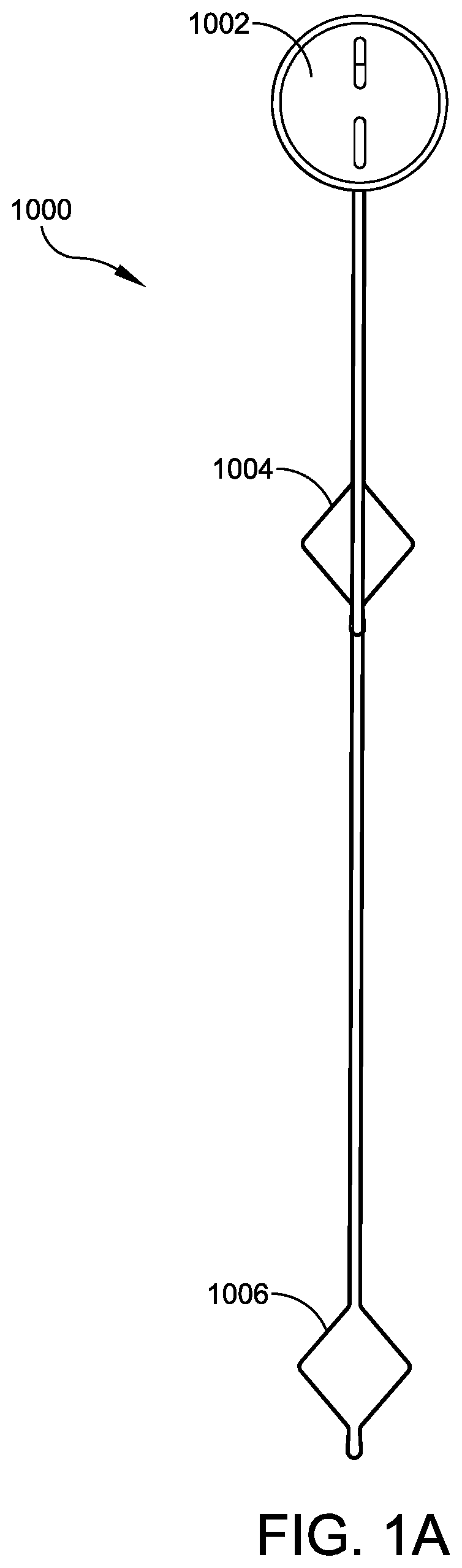
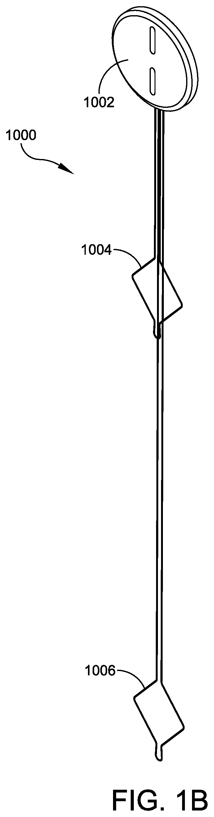
[0009] FIGS. 1A-1B illustrate respective front and perspective views of one embodiment of a multiple suture threader;
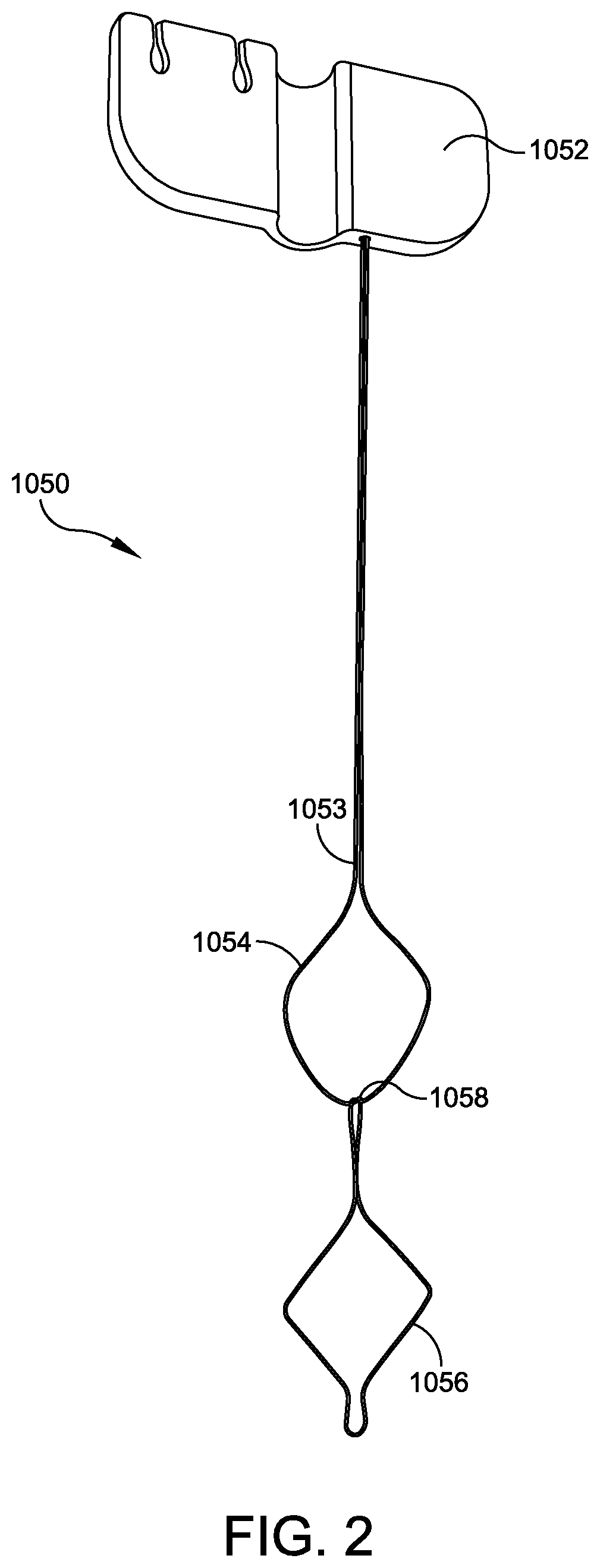
[0010] FIG. 2 illustrates a perspective view another embodiment of a multiple suture threader;
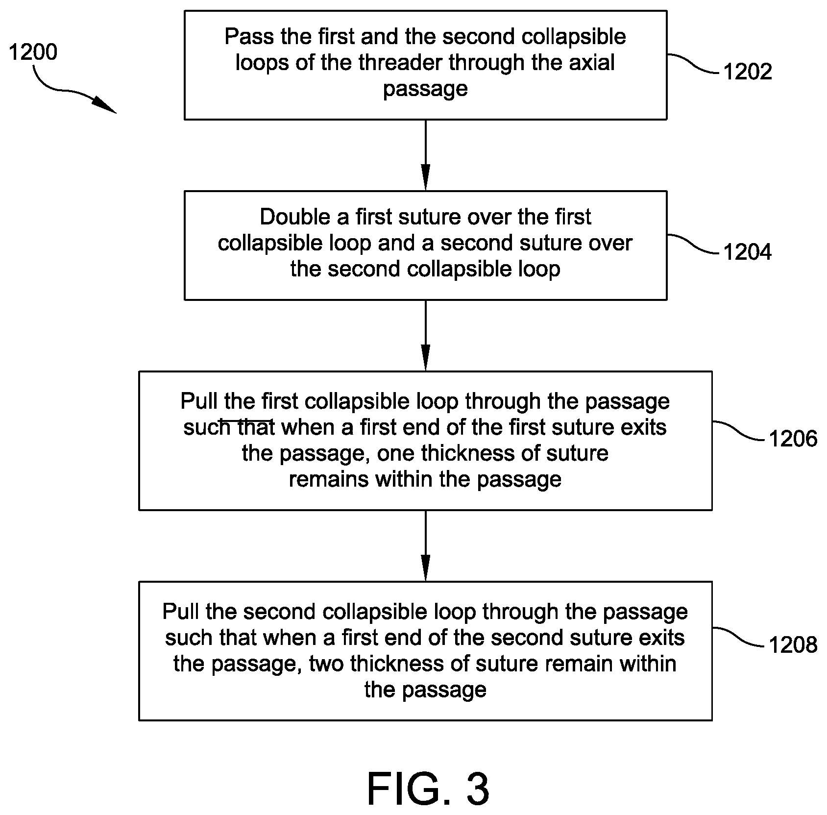
[0011] FIG. 3 provides a flowchart depicting an exemplary process for threading sutures through a narrow passage using the multiple suture threader of FIGS. 1A-1B;
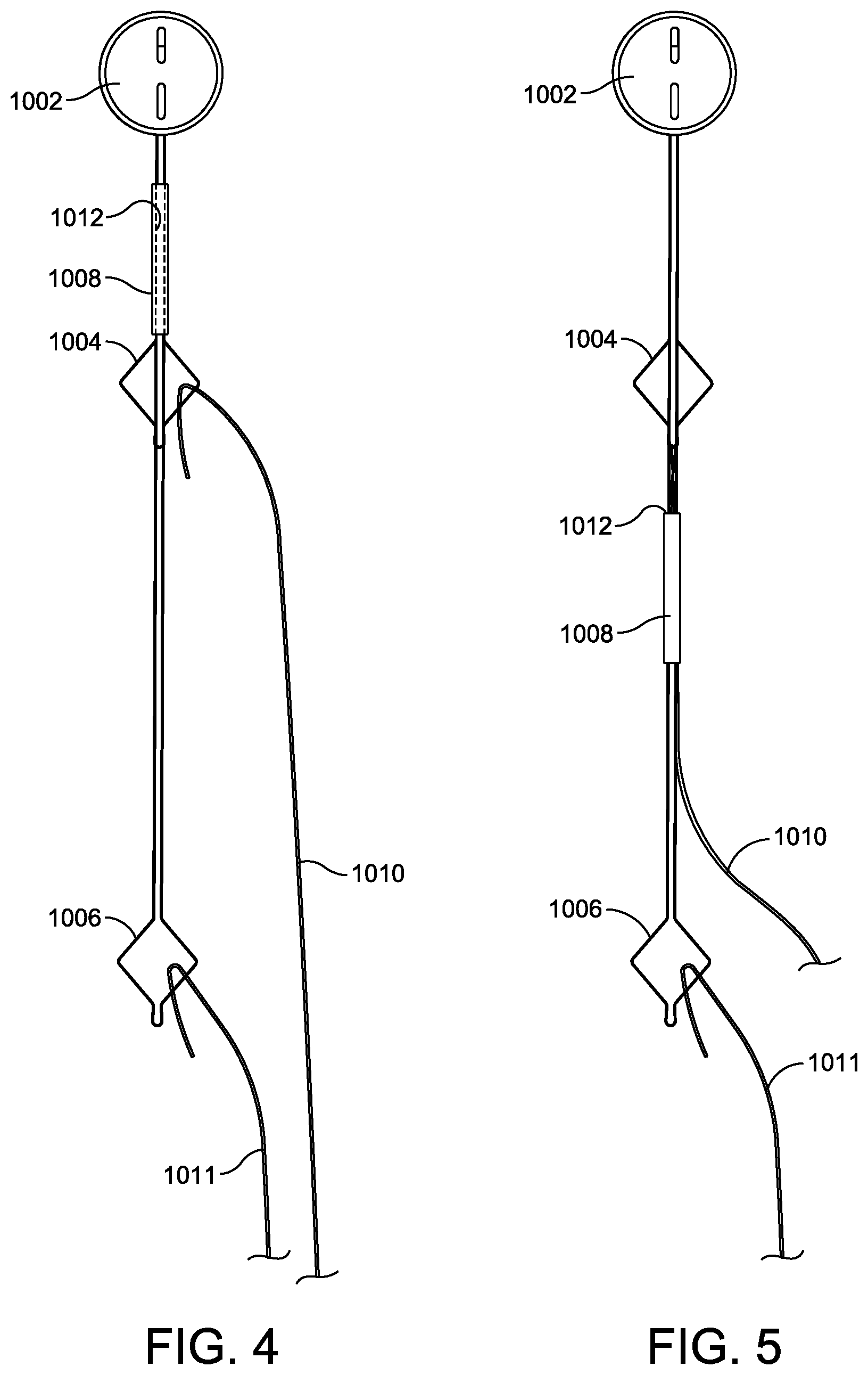
[0012] FIG. 4 illustrates a front view of the multiple suture threader of FIGS. 1A-1B with a first collapsible loop and a second collapsible loop in a starting position relative to the narrow passage;
[0013] FIG. 5 illustrates a front view of the multiple suture threader after the first collapsible loop and a doubled first suture have been passed through the narrow passage;
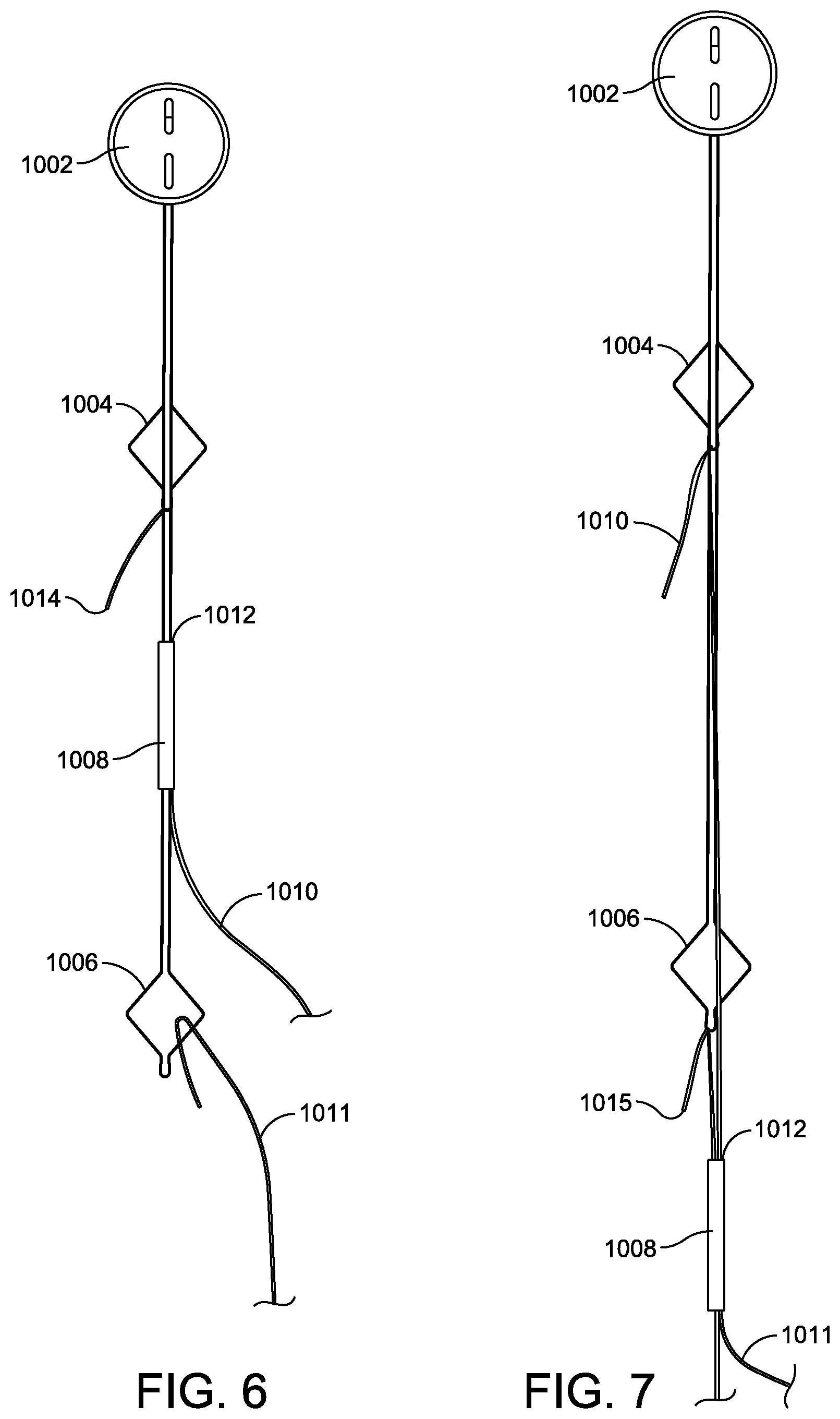
[0014] FIG. 6 illustrates a front view of the multiple suture threader after a first end of the first suture has exited the narrow passage; and
[0015] FIG. 7 illustrates a front view of the multiple suture threader after the second collapsible loop and a first end of the second suture have exited the narrow passage.
DETAILED DESCRIPTION
[0016] Embodiments are described more fully below in sufficient detail to enable those skilled in the art to practice the system and method. However, embodiments may be implemented in many different forms and should not be construed as being limited to the embodiments set forth herein. The following detailed description is, therefore, not to be taken in a limiting sense.
[0017] The technology discussed herein relates to apparatus and corresponding methods of use for threading sutures through narrow passages in a manner that reduces the amount of material passed at any one time through a passage such as, for example, an instrument cannula, a surgical implant sheath or tube, a bodily lumen (e.g., an arterial lumen, an intestinal lumen), a bone tunnel, and so on. This reduction in the amount of pass-through material allows for a reduced passage diameter and, in instances of a passage through an item of medical hardware, a reduced size of the associated device or hardware forming the passage (e.g., reduced size of suture fixation hardware, reduced size of a bone tunnel sheath, etc.).
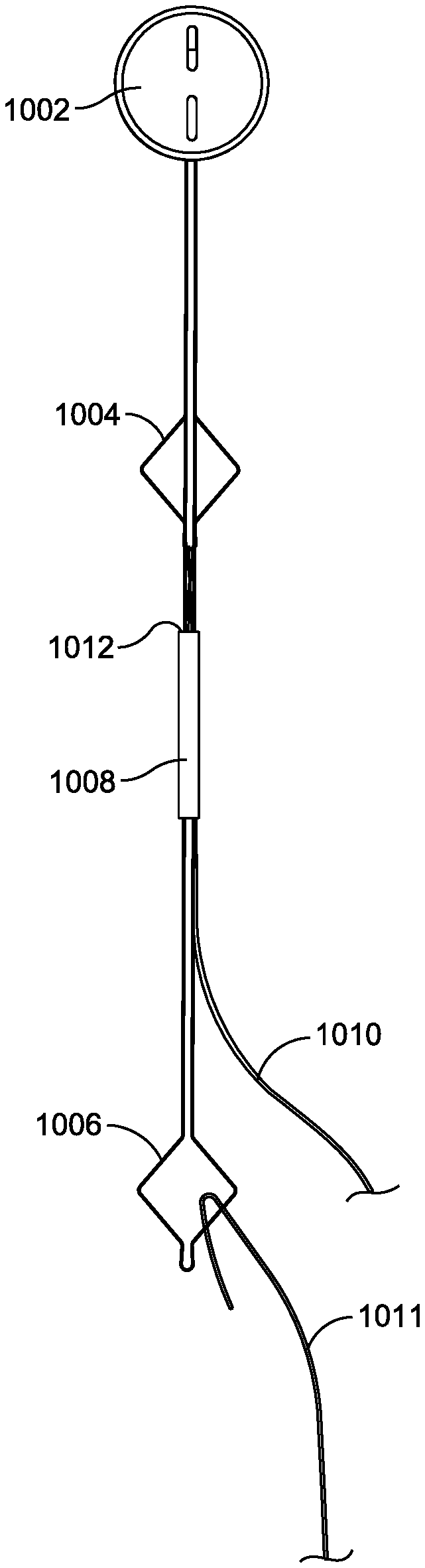
[0018] FIGS. 1A-1B illustrate front and perspective views of one embodiment of a suture threader 1000 for use with any passage through which the threading of suture or another flexible strand is desired in an implant, instrument, tissue, or otherwise. In this embodiment, suture threader 1000 may include a handle 1002, a first collapsible loop 1004 connected to the handle 1002, and a second collapsible loop 1006 independently connected to the handle 1002. The second loop 1006 is spaced or offset distally relative to the first loop 1004. In this embodiment, the two loops 1004, 1006 may be formed of and suspended from the handle by discrete strands or filaments of any appropriate material such as, for example, a flexible wire. In another embodiment, one or both of loop 1002 or loop 1004 may be provided in a non-collapsible configuration, which may include, but is not limited to, a rigid configuration, a flexible configuration, or a semi-flexible configuration. Preferably they are formed from a shape memory material such as nitinol wire. Both of the loops 1004, 1006 are configured to pass through the passage through which suture is to be passed.
[0019] FIG. 2 illustrates an alternative embodiment of a multiple suture threader 1050, which is similar to threader 1000. However, rather than two discreet collapsible loops 1004, 1006 formed of separate strands or wires that are each discretely connected with the handle 1002, threader 1050 includes a single filament 1053 that connects with the handle 1050 and forms both a first proximal collapsible loop 1054 and a second distal collapsible loop 1056. A base 1058 of the first collapsible loop 1054 may be formed by crossing the filament 1053 over itself at the base 1058 before forming the second distal collapsible loop 1056. In other embodiments, the base 1058 of the first collapsible loop 1054 may be formed via other methods such as, for example, laser welding, adhesive bonding, diffusion bonding, and/or crimping.
[0020] In some embodiments, the first and the second collapsible loops 1054, 1056 may be formed of a polymer strand such as a monofilament or a braided suture. In these embodiments, the base 1058 of the first collapsible loop 1054 may be formed via any appropriate method including, for example, adhesive bonding, ultrasonic welding, radio frequency welding, or melt bonding.
[0021] FIG. 3 provides a flowchart detailing an exemplary threading process 1200 using the exemplary threader 1000, while FIGS. 4-7 illustrate the corresponding steps of the threading process 1200. FIGS. 4-7 show the suture threader 1000 in use with a generic sleeve 1008, though it should be understood that embodiments of the threaders 1000, 1050 may be used to thread a suture 1010 or other flexible strand though any passage through which suture threading is desired in an implant, an instrument, human tissue, or otherwise. For example, embodiments of the suture threaders 1000, 1050 may be used with the fixation anchor 1440 disclosed in FIGS. 26-29 of U.S. patent application Ser. No. 15/641,573, entitled "INTRA JOINT STABILIZATION CONSTRUCT"; and co-filed with this application on Jul. 5, 2017 or with any other appropriate fixation hardware, implant, instrument, or human tissue lumen.
[0022] The exemplary threading process 1200 begins, as shown in FIG. 4, with the loops 1004, 1006 being passed through an axial passage 1012 of the sleeve 1008 (FIG. 3, 1202). One or more first sutures 1010 are then doubled over the first loop 1004, and one or more second sutures 1011 are doubled over the second loop 1006 (FIG. 3, 1204). In the example of FIGS. 4-7, a single suture is doubled over each loop 1004, 1006. However, the threader 1000 may be used with one or more sutures 1010, 1011 doubled over each loop in any desired and/or appropriate combination.
[0023] In FIG. 5, the first collapsible loop 1004 has been pulled through the passage 1012 formed within the sleeve 1008 (FIG. 3, 1206). At the position shown in FIG. 5, two thicknesses of the first suture 1010 are being passed through the passage 1012 due to the first suture 1010 being doubled over. At the position shown in FIG. 6, a first end 1014 of the first suture 1010 has exited the passage 1012 so that only one thickness of the first suture 1010 remains within the passage 1012.
[0024] Further pulling of the threader 1000 pulls the second collapsible loop 1006 into the passage 1012 (FIG. 3, 1208). At this point, three suture thicknesses remain within the passage--one thickness of the first suture 1010 and two thicknesses of the second suture 1011. At the position shown in FIG. 7, both the first and the second loops 1004, 1006 have exited the passage 1012, along with a first end 1015 of the second suture 1011. At this point, only two thicknesses of suture--one thickness each of the first suture 1010 and the second suture 1011--remain within the passage 1012.
[0025] By separating the first and the second collapsible loops 1004, 1006 axially, the maximum number of suture thicknesses that must be passed simultaneously to thread a given number of sutures through the passage 1012 is reduced. If the number of sutures doubled over each loop is the same, then the total suture thickness that must be passed is reduced by 25%. For example, as described above, if one suture is doubled over each of the first and the second collapsible loops 1004, 1006, then the maximum number of suture thicknesses that must be passed simultaneously to thread both of the sutures is three, a 25% reduction from the four suture thicknesses that must be passed simultaneously if two sutures are doubled over a traditional single loop threader. In another example, if two sutures are doubled over each of the first and the second loops 1004, 1006, then the maximum number of suture thicknesses that must be passed simultaneously to thread all four sutures is limited to six. With a traditional threader, the maximum number of suture thicknesses that must be passed simultaneously to thread all four sutures is eight, or the total number of sutures doubled over the single loop of the traditional threader (i.e., 4.times.2). In a further example, if three sutures are doubled over each of the first and the second loops 1004, 1006, then the maximum number of suture thicknesses that must be passed simultaneously to thread all six sutures is nine. With a traditional threader, the maximum number of suture thicknesses that must be passed simultaneously to thread all six sutures is twelve, or the total number of sutures doubled over the single loop of the traditional threader (i.e., 6.times.2).
[0026] Notably, any number of threads may be doubled over each of the first and the second loops 1004, 1006, and the numbers may be equal across the two loops or different, as appropriate. Depending on the use and the varying numbers of sutures doubled over each of the first and the loops, embodiments of the multiple suture threaders 1000, 1050 may achieve up to a 50% reduction in suture traffic.
[0027] Further, while the embodiments shown in FIGS. 1-2 and 4-7 features two axially-spaced collapsible loops, other embodiments may feature additional axially spaced loops, as desired for a variety of threading applications.
[0028] Embodiments of the threader disclosed herein are particularly advantageous where sutures need to be passed through a narrow passage. When sutures are threaded using a loop-style suture threader, the sutures are doubled over the loop. With a narrow passage and multiple sutures, the doubled over ends create excess bulk that cannot be easily passed through the passage. The suture threaders 1000, 1050 reduces the suture traffic through the passage, or reduce the number of suture thicknesses that must be passed simultaneously by spacing the doubled over ends axially apart so that only a portion of the doubled over ends is passed through the passage at any one time.
[0029] Although the above embodiments have been described in language that is specific to certain structures, elements, compositions, and methodological steps, it is to be understood that the technology defined in the appended claims is not necessarily limited to the specific structures, elements, compositions and/or steps described. Rather, the specific aspects and steps are described as forms of implementing the claimed technology. Since many embodiments of the technology can be practiced without departing from the spirit and scope of the invention, the invention resides in the claims hereinafter appended.
* * * * *
D00000
D00001
D00002
D00003
D00004
D00005
D00006
XML
uspto.report is an independent third-party trademark research tool that is not affiliated, endorsed, or sponsored by the United States Patent and Trademark Office (USPTO) or any other governmental organization. The information provided by uspto.report is based on publicly available data at the time of writing and is intended for informational purposes only.
While we strive to provide accurate and up-to-date information, we do not guarantee the accuracy, completeness, reliability, or suitability of the information displayed on this site. The use of this site is at your own risk. Any reliance you place on such information is therefore strictly at your own risk.
All official trademark data, including owner information, should be verified by visiting the official USPTO website at www.uspto.gov. This site is not intended to replace professional legal advice and should not be used as a substitute for consulting with a legal professional who is knowledgeable about trademark law.