Selectively Reconfigurable Carrying Case With Perimetrical Zipper
Kim; Brandon ; et al.
U.S. patent application number 17/000683 was filed with the patent office on 2021-02-25 for selectively reconfigurable carrying case with perimetrical zipper. The applicant listed for this patent is Brevite LLC. Invention is credited to Philip de los Reyes, Brandon Kim.
| Application Number | 20210052052 17/000683 |
| Document ID | / |
| Family ID | 1000005061404 |
| Filed Date | 2021-02-25 |


| United States Patent Application | 20210052052 |
| Kind Code | A1 |
| Kim; Brandon ; et al. | February 25, 2021 |
SELECTIVELY RECONFIGURABLE CARRYING CASE WITH PERIMETRICAL ZIPPER
Abstract
Collapsible or otherwise selectively reconfigurable carrying cases, and methods for the manufacture and use thereof, are provided. The carrying cases are constructed of at least two body panels made of puncture-resistant material and are selectively reconfigurable between an expanded configuration and a collapsed configuration by the use of a zipper disposed around all or substantially all of a perimeter or circumference of the at least two body panels. The carrying cases are adapted to receive and securely store and carry fragile items, e.g. cameras and photographic equipment, when in the expanded configuration and to collapse or otherwise significantly reduce in volume when in the collapsed configuration for easy storage and transportation.
| Inventors: | Kim; Brandon; (Hingham, MA) ; de los Reyes; Philip; (Berkeley, CA) | ||||||||||
| Applicant: |
|
||||||||||
|---|---|---|---|---|---|---|---|---|---|---|---|
| Family ID: | 1000005061404 | ||||||||||
| Appl. No.: | 17/000683 | ||||||||||
| Filed: | August 24, 2020 |
Related U.S. Patent Documents
| Application Number | Filing Date | Patent Number | ||
|---|---|---|---|---|
| 62891059 | Aug 23, 2019 | |||
| Current U.S. Class: | 1/1 |
| Current CPC Class: | A45C 7/0063 20130101; A45C 7/0077 20130101; A45F 2200/0533 20130101; A45C 7/009 20130101; A45C 13/103 20130101; A45C 3/001 20130101 |
| International Class: | A45C 7/00 20060101 A45C007/00; A45C 3/00 20060101 A45C003/00; A45C 13/10 20060101 A45C013/10 |
Claims
1. A carrying case, comprising: first and second body panels, each of the first and second body panels comprising a substantially puncture-resistant material; and a zipper, wherein a first set of teeth of the zipper is disposed about substantially all of a perimeter or circumference of the first body panel and a second set of teeth of the zipper is disposed about substantially all of a perimeter or circumference of the second body panel, wherein a user may selectively reconfigure the carrying case between an expanded configuration and a collapsed configuration by selectively fastening or unfastening the zipper, wherein, when the zipper is fully fastened, corresponding edges of the first and second body panels are joined to form a plurality of walls defining an enclosed interior volume such that the carrying case is in the expanded configuration, and wherein, when the zipper is fully unfastened, corresponding edges of the first and second body panels are disjoined and do not define an enclosed interior volume such that the carrying case is in the collapsed configuration.
2. The carrying case of claim 1, wherein the plurality of walls comprises a top wall, a bottom wall, two side walls, and two end walls such that the interior volume defined thereby is substantially in the shape of a rectangular prism.
3. The carrying case of claim 1, wherein the substantially puncture-resistant material is a polymeric material.
4. The carrying case of claim 3, wherein the polymeric material is a nylon.
5. The carrying case of claim 4, wherein the nylon is 210D nylon.
6. The carrying case of claim 1, wherein at least one body panel comprises a multi-layer or composite portion.
7. The carrying case of claim 6, wherein an outer surface of the at least one body panel comprises the substantially puncture-resistant material.
8. The carrying case of claim 6, wherein an inner surface of the at least one body panel comprises a durable cushioning material.
9. The carrying case of claim 6, wherein the multi-layer or composite portion comprises an outer surface layer, an inner surface layer, and at least one intermediate layer.
10. The carrying case of claim 1, adapted to receive and securely carry a camera or other photographic equipment within the interior volume when in the expanded configuration.
11. A collapsible insert for a carrying case, comprising: back and front body panels, each of the back and front body panels comprising a substantially puncture-resistant material; and a zipper, wherein a first set of teeth of the zipper is disposed about substantially all of a perimeter or circumference of the back body panel and a second set of teeth of the zipper is disposed about substantially all of a perimeter or circumference of the front body panel, wherein a user may selectively reconfigure the collapsible insert between an expanded configuration and a collapsed configuration by selectively fastening or unfastening the zipper, wherein, when the zipper is fully fastened, corresponding edges of the back and front body panels are joined to form a plurality of walls defining an enclosed interior volume such that the collapsible insert is in the expanded configuration, and wherein, when the zipper is fully unfastened, corresponding edges of the back and front body panels are disjoined and do not define an enclosed interior volume such that the collapsible insert is in the collapsed configuration.
12. The collapsible insert of claim 11, wherein the plurality of walls comprises a top wall, a bottom wall, a left wall, a right wall, a back wall, and a front wall such that the interior volume defined thereby is substantially in the shape of a trapezoidal prism.
13. The collapsible insert of claim 11, wherein the substantially puncture-resistant material is a polymeric material.
14. The collapsible insert of claim 13, wherein the polymeric material is a nylon.
15. The collapsible insert of claim 14, wherein the nylon is 210D nylon.
16. The collapsible insert of claim 11, wherein at least one body panel comprises a multi-layer or composite portion.
17. The collapsible insert of claim 16, wherein an outer surface of the at least one body panel comprises the substantially puncture-resistant material.
18. The collapsible insert of claim 16, wherein an inner surface of the at least one body panel comprises a durable cushioning material.
19. The collapsible insert of claim 16, wherein the multi-layer or composite portion comprises an outer surface layer, an inner surface layer, and at least one intermediate layer.
20. The collapsible insert of claim 11, adapted to receive and securely carry a camera or other photographic equipment within the interior volume when in the expanded configuration.
Description
CROSS-REFERENCE TO RELATED APPLICATION
[0001] This application claims the benefit of priority of U.S. Provisional Patent Application 62/891,059, filed 23 Aug. 2019, the entirety of which is incorporated herein by reference.
FIELD OF THE INVENTION
[0002] The present disclosure is directed generally toward devices and systems for the secure carrying of items, and particularly toward backpacks, cases, and the like, and inserts and attachments therefor, for the safe and secure carrying of cameras and photographic equipment and other fragile items.
BACKGROUND OF THE INVENTION
[0003] There are many situations in which it may be desirable to carry fragile items, including but not limited to cameras and related photographic equipment, in storage and transport devices that have a minimum of weight or bulk, such as a backpack or similar type of pack or case. Some such situations include, but are not limited to, nature photography and other forms of outdoor photography, where a photographer must often carry their own gear in rugged or remote environments. However, conventional carrying cases generally suffer from an important drawback: there is necessarily a tradeoff between the minimization of weight or bulk of the carrying case and the degree of protection offered to the fragile items. In particular, cases with soft and/or flexible sides frequently do not adequately protect the fragile items inside from impact, vibration, etc., while cases with hard and/or substantially rigid sides frequently are excessively heavy and have a substantially fixed volume, such that the case remains bulky even when the fragile items are not inside.
[0004] Accordingly, there is a need in the art for carrying cases, and inserts and attachments therefor, for cameras, photographic equipment, and other fragile items that are easy to use and protect the fragile items inside from impact, vibration, and other forms of damage, while also minimizing the weight and bulk of the carrying case and/or insert or attachment. In particular, it would be advantageous for a volume of the case, insert, or attachment to be variable and/or reconfigurable, such that the volume can be expanded to provide ample space for carrying the items when necessary and collapsed when the items are not being carried.
SUMMARY OF THE INVENTION
[0005] It is one aspect of the present invention to provide a carrying case, comprising first and second body panels, each of the first and second body panels comprising a substantially puncture-resistant material; and a zipper, wherein a first set of teeth of the zipper is disposed about substantially all of a perimeter or circumference of the first body panel and a second set of teeth of the zipper is disposed about substantially all of a perimeter or circumference of the second body panel, wherein a user may selectively reconfigure the carrying case between an expanded configuration and a collapsed configuration by selectively fastening or unfastening the zipper, wherein, when the zipper is fully fastened, corresponding edges of the first and second body panels are joined to form a plurality of walls defining an enclosed interior volume such that the carrying case is in the expanded configuration, and wherein, when the zipper is fully unfastened, corresponding edges of the first and second body panels are disjoined and do not define an enclosed interior volume such that the carrying case is in the collapsed configuration.
[0006] In embodiments, the plurality of walls may comprise a top wall, a bottom wall, two side walls, and two end walls such that the interior volume defined thereby is substantially in the shape of a rectangular prism.
[0007] In embodiments, the substantially puncture-resistant material may be a polymeric material. The polymeric material may, but need not, be a nylon, which may, but need not, be 210D nylon.
[0008] In embodiments, at least one body panel may comprise a multi-layer or composite portion An outer surface of the at least one body panel may, but need not, comprise the substantially puncture-resistant material. An inner surface of the at least one body panel may, but need not, comprise a durable cushioning material. The multi-layer or composite portion may, but need not, comprise an outer surface layer, an inner surface layer, and at least one intermediate layer.
[0009] In embodiments, the carrying case may be adapted to receive and securely carry a camera or other photographic equipment within the interior volume when in the expanded configuration.
[0010] It is another aspect of the present invention to provide a collapsible insert for a carrying case, comprising back and front body panels, each of the back and front body panels comprising a substantially puncture-resistant material; and a zipper, wherein a first set of teeth of the zipper is disposed about substantially all of a perimeter or circumference of the back body panel and a second set of teeth of the zipper is disposed about substantially all of a perimeter or circumference of the front body panel, wherein a user may selectively reconfigure the collapsible insert between an expanded configuration and a collapsed configuration by selectively fastening or unfastening the zipper, wherein, when the zipper is fully fastened, corresponding edges of the back and front body panels are joined to form a plurality of walls defining an enclosed interior volume such that the collapsible insert is in the expanded configuration, and wherein, when the zipper is fully unfastened, corresponding edges of the back and front body panels are disjoined and do not define an enclosed interior volume such that the collapsible insert is in the collapsed configuration.
[0011] In embodiments, the plurality of walls may comprise a top wall, a bottom wall, a left wall, a right wall, a back wall, and a front wall such that the interior volume defined thereby is substantially in the shape of a trapezoidal prism.
[0012] In embodiments, the substantially puncture-resistant material may be a polymeric material. The polymeric material may, but need not, be a nylon, which may, but need not, be 210D nylon.
[0013] In embodiments, at least one body panel may comprise a multi-layer or composite portion. An outer surface of the at least one body panel may, but need not, comprise the substantially puncture-resistant material. An inner surface of the at least one body panel may, but need not, comprise a durable cushioning material. The multi-layer or composite portion may, but need not, comprise an outer surface layer, an inner surface layer, and at least one intermediate layer.
[0014] In embodiments, the collapsible insert may be adapted to receive and securely carry a camera or other photographic equipment within the interior volume when in the expanded configuration.
BRIEF DESCRIPTION OF THE DRAWINGS
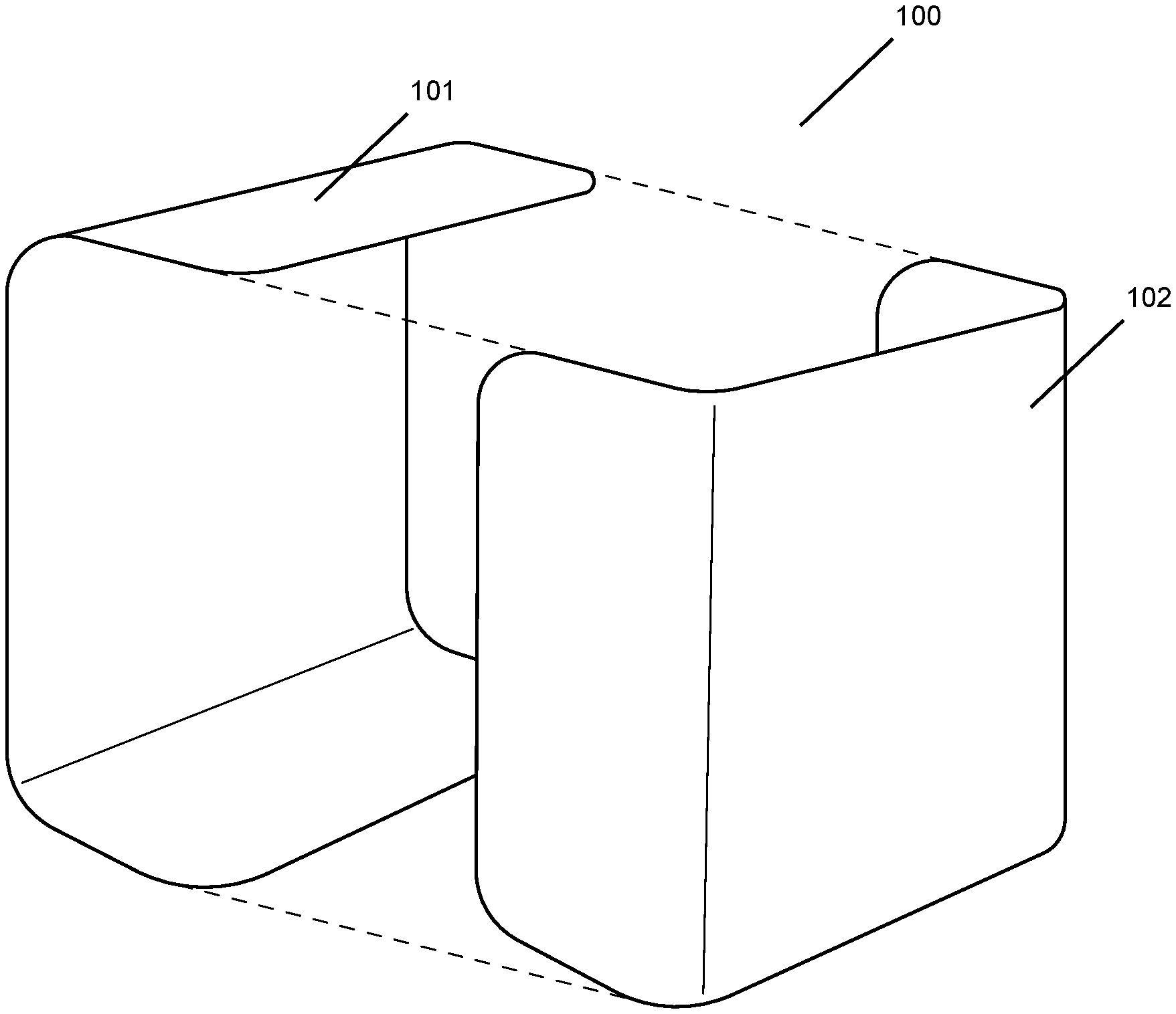
[0015] FIG. 1 is an exploded view of a collapsible carrying case in accordance with embodiments of the present disclosure.
[0016] FIGS. 2A and 2B are plan views of outer and inner surfaces, respectively, of a first body panel of a collapsible carrying case in accordance with embodiments of the present disclosure.
[0017] FIGS. 3A and 3B are plan views of outer and inner surfaces, respectively, of a second body panel of a collapsible carrying case in accordance with embodiments of the present disclosure.
[0018] FIG. 4 is an exploded view of the layers of a multi-layer body panel of a collapsible carrying case in accordance with embodiments of the present disclosure.
[0019] FIGS. 5A, 5B, and 5C are, respectively, a plan view, a cross-sectional view, and a perspective view of various features of a zipper of a collapsible carrying case in accordance with embodiments of the present disclosure.
[0020] FIG. 6 is a perspective view of a collapsible carrying case in an expanded configuration in accordance with embodiments of the present disclosure.
[0021] FIGS. 7A and 7B are perspective views illustrating additional and/or optional features of a collapsible carrying case in accordance with embodiments of the present disclosure.
[0022] FIGS. 8A, 8B, and 8C are plan views of various components of a padded insert or divider for a carrying case in accordance with embodiments of the present disclosure.
[0023] FIGS. 9A, 9B, and 9C are perspective views of a collapsible insert for a carrying case in accordance with embodiments of the present disclosure.
DETAILED DESCRIPTION OF THE INVENTION
[0024] The phrases "at least one," "one or more," "or," and "and/or" are open-ended expressions that are both conjunctive and disjunctive in operation. For example, each of the expressions "at least one of A, B and C," "at least one of A, B, or C," "one or more of A, B, and C," "one or more of A, B, or C," "A, B, and/or C," and "A, B, or C" means A alone, B alone, C alone, A and B together, A and C together, B and C together, or A, B and C together.
[0025] The term "a" or "an" entity refers to one or more of that entity. As such, the terms "a" (or "an"), "one or more," and "at least one" can be used interchangeably herein. It is also to be noted that the terms "comprising," "including," and "having" can be used interchangeably.
[0026] Aspects of the present invention provide for a carrying case, or insert or attachment therefor, that is reconfigurable between an expanded configuration and a collapsed configuration, enabling a user to expand the carrying case, insert, or attachment when needed to securely hold and transport fragile items, e.g. cameras and photographic equipment, and collapse the carrying case, insert, or attachment at other times to minimize the volume and bulk of the case, insert, or attachment. This reconfiguration is accomplished by means of a perimetrical zipper that runs around substantially all of a circumferential or perimetrical edge of two body panels; a user may selectively reconfigure the case, attachment, or insert into the expanded configuration by zipping the body panels together with the zipper, and into the collapsed configuration by unzipping the body panels apart (or partially apart) with the zipper. In embodiments, cases, inserts, and attachments of the present invention take the general shape of a rectangular prism, with each of the two body panels comprising three of the six rectangular faces of the rectangular prism and the zipper extending around substantially all of a perimeter of each of the six faces. In embodiments, the cases, attachments, and inserts of the present invention can securely hold and transport a significant number and/or weight of fragile items, including but not limited to cameras and photographic equipment, when having the shape of a complete rectangular prism in the expanded configuration, and can also flatten completely for easy transport and storage when in the collapsed configuration.
[0027] FIG. 1 illustrates a carrying case 100 according to an embodiment of the present disclosure. The carrying case 100 includes two body panels 101,102, which interlock as shown when the carrying case 100 is in an expanded configuration. As illustrated in FIG. 1, generally, when the carrying case 100 is in the expanded configuration, each body panel 101,102 will tend to have a generally horseshoe or C shape, with the open ends of the horseshoe or C shapes of the two panels disposed orthogonally to and interlocking with each other. The construction of each body panel 101,102 includes at least one layer of a puncture-resistant, and preferably flexible and relatively lightweight, material, which may comprise, by way of non-limiting example, a polymer and/or a composite material; in many embodiments, as described in greater detail below, each panel may have a multi-layer construction in which at least one, and optionally all, layers are constructed of a puncture-resistant material. In the embodiment illustrated in FIG. 1, the carrying case 100, when in the expanded configuration, has a generally rectangular cross-section and a substantially uniform depth or thickness, thereby providing an overall shape of a rectangular prism, but it is expressly contemplated that carrying cases according to the present invention may have any suitable cross-section, depth/thickness (which may be uniform or spatially varying), and/or shape when in the expanded configuration. The two body panels 101,102 collectively define walls of the carrying case 100, which may be of any thickness (which may be uniform or spatially varying) suitable to provide puncture resistance and to cushion and protect the fragile items inside the carrying case 100 against impact, vibration, etc. The walls of the carrying case 100 surround and define an interior volume adapted to receive fragile items, such as (but not necessarily limited to) cameras and related photographic equipment. As described in greater detail below and as will be appreciated by those of skill in the art, one or both body panels 101,102 will generally comprise a door, aperture, etc. that allows the items inside the carrying case 100 to be selectively inserted or removed and to otherwise prevent access to and shifting, impact, etc. of the items.
[0028] In embodiments, either or both of the body panels 101,102 may be molded or otherwise constructed of a single piece of material, which may be a multi-layer or composite material, but in all cases are constructed to form a snug fit with each other when zipped together using the zipper (as described in greater detail below) to place the carrying case 100 in the expanded configuration. The interior volume surrounded and defined by the body panels 101,102 when the case is in the expanded configuration may have any suitable volume to accommodate various types and sizes of fragile item, and may be selected by those of skill in the art to provide a case of any appropriate size.
[0029] A reconfiguration zipper 3 runs along all or substantially all of a perimeter or circumference of each of the two body panels 101,102; specifically, the two sets of teeth of the reconfiguration zipper 3 are disposed along the edges where the respective body panels 101,102 interlock or interconnect. As a result of this placement of the reconfiguration zipper 3, a user may selectively reconfigure the carrying case 100 between the expanded configuration and the collapsed configuration merely by moving a zipper pull 31 of the reconfiguration zipper 3. When the reconfiguration zipper 3 is fully zipped "up" or "together," corresponding edges of the two body panels 101,102 are fastened to each other to form the rectangular prism (or other desired shape) of the carrying case 100 in the expanded configuration; when the reconfiguration zipper 3 is fully zipped "apart," the corresponding edges of the two body panels 101,102 are unfastened, and the body panels 101,102 take the flat rectangular shapes shown in FIGS. 2A through 3B. In this way, the collapsed configuration of the carrying case 100 consists of two flat, rectangular panels of minimal thickness, which may be interconnected by the reconfiguration zipper 3 and/or zipper pull 31 at as little as a single point, thereby allowing the volume of the carrying case 100 to be minimized and storage of the carrying case 100 to be made easier when the carrying case 100 is not needed.
[0030] FIGS. 2A and 2B illustrate outer 101a and inner 101b surfaces, respectively, of a first body panel of a carrying case 100, e.g. the panel labeled 101 in FIG. 1, according to embodiments of the present disclosure. In the embodiment illustrated in FIGS. 2A and 2B, the first body panel 101 is a substantially flat, rectangular panel that, when the carrying case 100 is reconfigured from the collapsed configuration into the expanded configuration, is creased, crimped, folded, or otherwise re-shaped to form a substantial horseshoe or C shape. Preferably, the first body panel 101 has a composite or multi-layer construction; in the embodiment of the first body panel 101 illustrated in FIGS. 2A and 2B, the outer surface 101a of the first body panel 101 is constructed primarily of a flexible, resilient material that is resistant to puncture and tearing (e.g. a heavy-duty nylon), while the inner surface 101b of the first body panel 101 is constructed primarily of a durable cushioning material (e.g. Vellux.RTM.). A zipper 3 (known hereinafter as the reconfiguration zipper) is disposed around substantially all of the circumference or perimeter of the first body panel 101; as described in greater detail below, a user of the carrying case 100 may selectively reconfigure the carrying case 100 between the expanded configuration and the collapsible configuration by operation of the reconfiguration zipper 3. As illustrated in FIGS. 2A and 2B, either surface 101a,101b may have additional features and/or materials; by way of non-limiting example, as illustrated in FIG. 2A, the outer surface 101a may comprise a portion of webbed material 4 (e.g. a "window" allowing a user to view items inside the carrying case 100 without opening the case) and/or piping of a durable cushioning material 5 (which may be the same as or different from the durable cushioning material of the inner surface). According to embodiments of the present disclosure, the first body panel 101 may preferably have a total length L1 of about 19 inches. According to embodiments of the present disclosure, the first body panel 101 may preferably have a total width W1 of about 11 inches. It is to be expressly understood that the values provided in this paragraph for the dimensions of the first body panel 101 are exemplary only and are not limiting of the scope of the present invention.
[0031] FIGS. 3A and 3B illustrate outer 102a and inner 102b surfaces, respectively, of a second body panel of a carrying case 100, e.g. the panel labeled 102 in FIG. 1, according to embodiments of the present disclosure. In the embodiment illustrated in FIGS. 3A and 3B, the second body panel 102 is a substantially flat, rectangular panel that, when the carrying case 100 is reconfigured from the collapsed configuration into the expanded configuration, is creased, crimped, folded, or otherwise re-shaped to form a substantial horseshoe or C shape. Preferably, the second body panel 102 has a composite or multi-layer construction; in the embodiment of the second body panel 102 illustrated in FIGS. 3A and 3B, the outer surface 102a of the second body panel 102 is constructed primarily of a flexible, resilient material that is resistant to puncture and tearing (e.g. a heavy-duty nylon), while the inner surface 102b of the second body panel 102 is constructed primarily of a durable cushioning material (e.g. Vellux.RTM.). Materials of the second body panel 102 may be the same as or different from the materials of the first body panel 101. The reconfiguration zipper 3 is disposed around substantially all of the circumference or perimeter of the second body panel 102; as described in greater detail below, a user of the carrying case 100 may selectively reconfigure the carrying case 100 between the expanded configuration and the collapsible configuration by operation of the reconfiguration zipper 3. As illustrated in FIGS. 3A and 3B, either surface may have additional features and/or materials; by way of non-limiting example, additional zippers may be provided that provide a quick access door 6 and/or a front access door 7, as illustrated in greater detail in FIGS. 7A and 7B. According to embodiments of the present disclosure, the second body panel 102 may preferably have a total length L2 of about 20 inches. According to embodiments of the present disclosure, the second body panel 102 may preferably have a total width W2 of about 10 inches. According to embodiments of the present disclosure, the arcuate zipper 61 providing the quick access door 6 may generally define three sides of a trapezoid having a height H1 of about 4.25 inches and base lengths B1, B2 of 8 inches and 9 inches. According to embodiments of the present disclosure, the arcuate zipper 71 providing the front access door 7 may generally define three sides of a square having a side length Si of about 9.25 inches. It is to be expressly understood that the values provided in this paragraph for the dimensions of the second body panel 102 and various features thereof are exemplary only and are not limiting of the scope of the present invention.
[0032] FIG. 4 illustrates various layers of a multi-layer or composite body panel of a carrying case 100 according to embodiments of the present disclosure. The multi-layer body panel embodiment illustrated in FIG. 4 comprises four layers 11,12,13,14, but it is to be expressly understood that body panels of carrying cases of the present invention may also have only a single layer, or may be multi-layer body panels having two, three, or more than four layers. In the embodiment illustrated in FIG. 4, a first and outermost layer 11 (i.e. defining the outer surface) of the body panel comprises a flexible, resilient material that is resistant to puncture and tearing, which in this case is a heavy-duty nylon, specifically 210D nylon. Disposed inwardly of the first layer 11 is a second layer 12, which generally comprises a polyethylene or other similar polymer; preferably, the material of the second layer 12 is ductile and has high impact strength, allowing for variations in the interior volume of the carrying case 100 (when the case is in the expanded configuration) while still insulating the fragile items inside the carrying case 100 from impacts. Disposed inwardly of the second layer is a third layer 13, which generally comprises a closed-cell foam or similar material; preferably, the material of the third layer 13 provides compressive strength and dimensional stability to the carrying case 100, while also preventing absorption or transmission of water, mud, etc. Disposed inwardly of the third layer 13 is a fourth and innermost layer 14 (i.e. defining the inner surface of the body panel), which generally comprises a durable cushioning material, which in this case is Vellux.RTM.. Thus, as those of skill in the art will appreciate, each layer of a multi-layer body panel can provide a desirable characteristic such that the carrying case 100 as a whole enjoys the advantages and benefits of each material.
[0033] FIGS. 5A, 5B, and 5C illustrate a reconfiguration zipper 3 according to embodiments of the present disclosure. As FIG. 5A illustrates, a zipper pull 31 is provided that allows the user to selectively reconfigure the carrying case 100 between the expanded configuration and the collapsed configuration. As FIG. 5B illustrates, the teeth or "track" of the reconfiguration zipper 3 may form an overlap that prevents the two body panels 101,102 from being entirely disconnected from one another, thus preventing any possibility of one or more of the body panels becoming separated or lost relative to the other body panel and improving the ease of reconfiguration. FIG. 5C illustrates an exemplary reconfiguration zipper 3 and zipper pull 31, though it is to be expressly understood that any suitable type and form of zipper and/or zipper pull may be provided. In particular, the zipper may be a coil zipper, an invisible zipper, a reverse coil zipper, a metal zipper, a plastic-molded zipper, an open-ended zipper, a two-way open-ended zipper, a two-way closed-ended zipper, a magnetic zipper, or any other suitable type of zipper; it may be preferable in some embodiments for the zipper to be air- and/or water-tight, particularly when the carrying case 100 is intended to be water-resistant or waterproof. Optionally, the reconfiguration zipper 3 may be provided with an anti-slide lock that may allow the user to lock the zipper pull in a desired position, thus preventing the zipper from opening or closing (and thus the carrying case 100 from reconfiguring) unexpectedly or inadvertently.
[0034] FIG. 6 illustrates a carrying case 100 in the expanded configuration according to embodiments of the present disclosure. In this embodiment, a user has positioned the zipper pull 31 such that the reconfiguration zipper 3, which runs about substantially all of the perimeter of both body panels 101,102, is zipped fully "up" or "together," thereby joining corresponding edges of the first and second body panels 101,102 to place the carrying case 100 in the expanded configuration. In this embodiment the carrying case 100, in the expanded configuration, takes the shape of a rectangular prism, though as previously described, it is to be expressly understood that the carrying case 100 may have any desired shape or cross-section in the expanded configuration. The embodiment of the carrying case 100 illustrated in FIG. 6 has been further provided with various additional and/or optional features, including a portion of a webbed material 4 to provide a "window" into the interior of the case. The carrying case 100 may, but need not, further be provided with a branding area on which may be provided text, a logo, or other similar marks.
[0035] FIG. 7A illustrates a carrying case 100 in an expanded configuration and having a quick access door 6 according to embodiments of the present disclosure. In this embodiment, an arcuate zipper or other fastener 61 has been provided on one of the first and second body panels 101,102 that defines and encloses a quick access volume for storing smaller items, e.g. writing utensils and the like. It is to be expressly understood that the quick access volume may take any suitable shape and be provided on any suitable face or body panel of the carrying case 100, and that the fastener 61 used to define and enclose the quick access volume may be any suitable fastener adapted to be quickly and easily fastened or unfastened by a user, e.g. a zipper, a button, a hook-and-loop fastener, an elastic fastener, a snap, etc. The quick access door 6 and quick access volume may be similar to or different from that depicted on the outside surface of the second body panel 102 in FIG. 3A.
[0036] FIG. 7B illustrates a carrying case 100 in an expanded configuration and having a front access door 7 according to embodiments of the present disclosure. In this embodiment, an arcuate zipper or other fastener 71 has been provided on one of the first and second body panels 101,102 that defines and encloses a front access volume for storing larger items, e.g. a camera, one or more camera lenses, and the like. It is to be expressly understood that the front access volume may take any suitable shape and be provided on any suitable face or body panel of the carrying case 100, and that the fastener 71 used to define and enclose the quick access volume may be any suitable fastener adapted to be easily fastened or unfastened by a user, e.g. a zipper, a button, a hook-and-loop fastener, an elastic fastener, a snap, etc.
[0037] FIGS. 8A, 8B, and 8C illustrate various components of a padded insert or divider for a carrying case 100 according to embodiments of the present disclosure. The padded insert or divider generally takes the form of a plurality of rectangular panels 201,202,203, which may be selectively affixed to each other to form an insert or divider having a predetermined shape or volume and/or selectively separated for collapsibility and easy storage. In the embodiment of the padded insert or divider illustrated in FIGS. 8A, 8B, and 8C, each panel 201,202,203 of the padded insert or divider is made primarily of a durable padding or soft fabric, e.g. Vellux.RTM., but is provided with a hook-and-loop fastener portion 204 at either end, by which each panel may be affixed to one or more other panels. In some embodiments, it may be desirable to provide each panel of the padded insert or divider with a "core" or inner layer of a more rigid material, such as a polyethylene or other polymer, to help the padded insert or divider retain its shape. Padded inserts or dividers according to this and other embodiments may serve any one or more of several purposes, including but not limited to dividing the interior volume of a carrying case 100 into discrete sections (e.g. to prevent impacts between two or more fragile items in the carrying case 100), improving the degree to which items in the carrying case 100 are insulated against impact and vibration, providing additional pockets or restraints for storing additional items, and so on. According to embodiments of the present disclosure, a first insert/divider panel 201 may preferably have a total width W3 of about 4 inches and a total length L3 of about 12 inches, of which a width of about 1 inch at either end is given over to the hook-and-loop fastener portion 204. According to embodiments of the present disclosure, a second insert/divider panel 202 may preferably have a total width W4 of about four inches and a total length L4 of about 9 inches, of which a width of about 1 inch at either end is given over to the hook-and-loop fastener portion 204; as illustrated in FIG. 8B, the second insert/divider panel 202 (or any other insert/divider panel) may comprise a transverse crease, crimp, or fold 205, by which a first portion 202a of the panel 202 can be disposed at an angle relative to a second portion 202b of the panel 202. According to embodiments of the present disclosure, a third insert/divider panel 203 may preferably have a total width W5 of about 4 inches and a total length L5 of about 4.5 inches, of which a width of about 1 inch at either end is given over to the hook-and-loop fastener portion 204. It is to be expressly understood that the values provided in this paragraph for the dimensions of the panels 201,202,203 of the padded inserts/dividers and various features thereof, and the shapes and configurations illustrated therein, are exemplary only and are not limiting of the scope of the present invention, and that carrying cases according to the present invention may be provided with or without padded inserts and/or dividers.
[0038] FIG. 9A illustrates a collapsible insert 300 for a carrying case according to an embodiment of the present disclosure. The collapsible insert 300 includes two body panels 301,302, which interlock when the collapsible insert 300 is in an expanded configuration.
[0039] Particularly, when the collapsible insert 300 is in the expanded configuration, the rear panel 301 is creased, crimped, folded, or otherwise reshaped such that top and bottom portions 301a,c are disposed at angles relative to central portion 301b; in this way, the top 301a, central 301b, and bottom 301c portions of the rear panel 301 form top, rear, and bottom surfaces, respectively, of the carrying case 300 when in the expanded configuration. Likewise, when the collapsible insert 300 is in the expanded configuration, the front panel 302 is creased, crimped, folded, or otherwise reshaped such that left and right portions 302a,c are disposed at angles relative to central portion 302b; in this way, the left 302a, central 302b, and right 302c portions of the front panel 302 form left, front, and right surfaces, respectively, of the carrying case 300 when in the expanded configuration. Generally, when the collapsible insert 300 is in the expanded configuration, each body panel 301,302 will tend to have a generally horseshoe or C shape, with the open ends of the horseshoe or C shapes of the two panels disposed orthogonally to and interlocking with each other, similar to the body panels of the carrying case 100 illustrated in FIG. 1. The construction of each body panel 301,302 includes at least one layer of a puncture-resistant, and preferably flexible and relatively lightweight, material, which may comprise, by way of non-limiting example, a polymer and/or a composite material; in many embodiments, as described in greater detail below, each panel may have a multi-layer construction in which at least one, and optionally all, layers are constructed of a puncture-resistant material. In the embodiment illustrated in FIG. 9A, the collapsible insert 300, when in the expanded configuration, has an overall shape of a trapezoidal prism (as illustrated in further detail in FIGS. 9B and 9C), but it is expressly contemplated that collapsible inserts according to the present invention may have any suitable cross-section, depth/thickness (which may be uniform or spatially varying), and/or shape when in the expanded configuration. The two body panels 301,302 collectively define walls of the collapsible insert 300, which may be of any thickness (which may be uniform or spatially varying) suitable to provide puncture resistance and to cushion and protect the fragile items inside the collapsible insert 300 against impact, vibration, etc. The walls of the collapsible insert 300 surround and define an interior volume adapted to receive fragile items, such as (but not necessarily limited to) cameras and related photographic equipment. As described in greater detail below and as will be appreciated by those of skill in the art, one or both body panels 301,302 will generally comprise a door, aperture, etc. that allows the items inside the collapsible insert 300 to be selectively inserted or removed and to otherwise prevent access to and shifting, impact, etc. of the items.
[0040] In embodiments, either or both of the body panels 301,302 may be molded or otherwise constructed of a single piece of material, which may be a multi-layer or composite material, but in all cases are constructed to form a snug fit with each other when zipped together using the zipper (as described in greater detail below) to place the collapsible insert 300 in the expanded configuration. The interior volume surrounded and defined by the body panels 301,302 when the insert is in the expanded configuration may have any suitable volume to accommodate various types and sizes of fragile item, and may be selected by those of skill in the art to provide a case of any appropriate size.
[0041] A reconfiguration zipper 3 runs along all or substantially all of a perimeter or circumference of each of the two body panels 301,302; specifically, the two sets of teeth of the reconfiguration zipper 3 are disposed along the edges where the respective body panels 301,302 interlock or interconnect. As a result of this placement of the reconfiguration zipper 3, a user may selectively reconfigure the collapsible insert between the expanded configuration and the collapsed configuration merely by moving a zipper pull (not shown) of the reconfiguration zipper 3. When the reconfiguration zipper 3 is fully zipped "up" or "together," corresponding edges of the two body panels 301,302 are fastened to each other to form the trapezoidal prism (or other desired shape) of the collapsible insert 300 in the expanded configuration; when the reconfiguration zipper 3 is fully zipped "apart," the corresponding edges of the two body panels 301,302 are unfastened, and the body panels 301,302 take the flat rectangular shapes shown in FIG. 9A. In this way, the collapsed configuration of the collapsible insert consists of two flat, rectangular panels of minimal thickness, which may be interconnected by the reconfiguration zipper 3 and/or zipper pull at as little as a single point, thereby allowing the volume of the collapsible insert 300 to be minimized and storage of the collapsible insert 300 to be made easier when the collapsible insert 300 is not needed.
[0042] FIG. 9B illustrates a collapsible insert 300 in the expanded configuration according to embodiments of the present disclosure in rear perspective view. In this embodiment, a user has positioned the zipper pull of the reconfiguration zipper such that the reconfiguration zipper 3, which runs about substantially all of the perimeter of both body panels 301,302, is zipped fully "up" or "together," thereby joining corresponding edges of the first and second body panels 301,302 to place the collapsible insert 300 in the expanded configuration. In this embodiment the collapsible insert 300, in the expanded configuration, takes the shape of a trapezoidal prism, though as previously described, it is to be expressly understood that the collapsible insert 300 may have any desired shape or cross-section in the expanded configuration. The collapsible insert 300 may, but need not, be further with various additional and/or optional features, such as a portion of a webbed material to provide a "window" into the interior of the case (not shown) or a branding area on which may be provided text, a logo, or other similar marks.
[0043] FIG. 9C illustrates a collapsible insert 300 in an expanded configuration and having a front access door 7 according to embodiments of the present disclosure in front perspective view. In this embodiment, an arcuate zipper or other fastener 71 has been provided on front body panel 302 that defines and encloses a front access volume for storing larger items, e.g. a camera, one or more camera lenses, and the like. It is to be expressly understood that the front access volume may take any suitable shape, and that the fastener 71 used to define and enclose the quick access volume may be any suitable fastener adapted to be easily fastened or unfastened by a user, e.g. a zipper, a button, a hook-and-loop fastener, an elastic fastener, a snap, etc. As illustrated in FIG. 9C, the collapsible insert 300 may include, or be adapted to work in conjunction with, a system of internal partitions or dividers (which may, but need not, be a padded insert or divider as illustrated in FIGS. 8A through 8C) to divide the front access volume of the collapsible insert 300 into discrete sections (e.g. to prevent impacts between two or more fragile items in the collapsible insert 300), improving the degree to which items in the collapsible insert 300 are insulated against impact and vibration, and/or provide additional pockets or restraints for storing additional items, and so on. It is to be expressly understood that carrying cases as illustrated in FIGS. 1 through 7B may, but need not, include, receive, or be adapted to work in conjunction with padded inserts or dividers as illustrated in FIGS. 8A through 8C and/or collapsible inserts as illustrated in FIGS. 9A through 9C. It is to be further expressly understood that padded inserts or dividers as illustrated in FIGS. 8A through 8C may, but need not, be adapted to be inserted into or otherwise work in conjunction with carrying cases as illustrated in FIGS. 1 through 7B and/or collapsible insert as illustrated in FIGS. 9A through 9C, and may, additionally or alternatively, be adapted to be inserted into or otherwise work in conjunction with other types of carrying case as known in the art. It is to be still further expressly understood that collapsible inserts or dividers as illustrated in FIGS. 9A through 9C may, but need not, be adapted to be inserted into or otherwise work in conjunction with carrying cases as illustrated in FIGS. 1 through 7B, and may, additionally or alternatively, be adapted to be inserted into or otherwise work in conjunction with other types of carrying case as known in the art. Particularly, one possible advantage and benefit of the present invention is that the functioning of a conventional backpack or carrying case can be improved or enhanced as described herein by providing a collapsible insert 300 as illustrated in FIGS. 9A through 9C in an interior volume thereof.
[0044] Several variations and modifications of the disclosure can be used. It would be possible to provide for some features of the disclosure without providing others.
[0045] Examples provided herein are intended to be illustrative and non-limiting. Thus, any example or set of examples provided to illustrate one or more aspects of the present disclosure should not be considered to comprise the entire set of possible embodiments of the aspect in question. Examples may be identified by the use of such language as "for example," "such as," "by way of example," "e.g.," and other language commonly understood to indicate that what follows is an example.
[0046] The present disclosure, in various embodiments, configurations, and aspects, includes components, methods, processes, systems and/or apparatus substantially as depicted and described herein, including various embodiments, sub-combinations, and subsets thereof. Those of skill in the art will understand how to make and use the systems and methods disclosed herein after understanding the present disclosure. The present disclosure, in various embodiments, configurations, and aspects, includes providing devices and processes in the absence of items not depicted and/or described herein or in various embodiments, configurations, or aspects hereof, including in the absence of such items as may have been used in previous devices or processes, e.g., for improving performance, achieving ease, and/or reducing cost of implementation.
[0047] The foregoing discussion of the disclosure has been presented for purposes of illustration and description. The foregoing is not intended to limit the disclosure to the form or forms disclosed herein. In the foregoing Detailed Description for example, various features of the disclosure are grouped together in one or more embodiments, configurations, or aspects for the purpose of streamlining the disclosure. The features of the embodiments, configurations, or aspects of the disclosure may be combined in alternate embodiments, configurations, or aspects other than those discussed above. This method of disclosure is not to be interpreted as reflecting an intention that the claimed disclosure requires more features than are expressly recited in each claim. Rather, as the following claims reflect, inventive aspects lie in less than all features of a single foregoing disclosed embodiment, configuration, or aspect. Thus, the following claims are hereby incorporated into this Detailed Description, with each claim standing on its own as a separate preferred embodiment of the disclosure.
[0048] Moreover, though the description of the disclosure has included description of one or more embodiments, configurations, or aspects and certain variations and modifications, other variations, combinations, and modifications are within the scope of the disclosure, e.g., as may be within the skill and knowledge of those in the art, after understanding the present disclosure. It is intended to obtain rights, which include alternative embodiments, configurations, or aspects to the extent permitted, including alternate, interchangeable and/or equivalent structures, functions, ranges, or steps to those claimed, whether or not such alternate, interchangeable and/or equivalent structures, functions, ranges, or steps are disclosed herein, and without intending to publicly dedicate any patentable subject matter.
* * * * *
D00000
D00001
D00002
D00003
D00004
D00005
D00006
D00007
D00008
XML
uspto.report is an independent third-party trademark research tool that is not affiliated, endorsed, or sponsored by the United States Patent and Trademark Office (USPTO) or any other governmental organization. The information provided by uspto.report is based on publicly available data at the time of writing and is intended for informational purposes only.
While we strive to provide accurate and up-to-date information, we do not guarantee the accuracy, completeness, reliability, or suitability of the information displayed on this site. The use of this site is at your own risk. Any reliance you place on such information is therefore strictly at your own risk.
All official trademark data, including owner information, should be verified by visiting the official USPTO website at www.uspto.gov. This site is not intended to replace professional legal advice and should not be used as a substitute for consulting with a legal professional who is knowledgeable about trademark law.