Aerosol Generating Article With Retractable Heat Source
Kuchen; David ; et al.
U.S. patent application number 16/969415 was filed with the patent office on 2021-02-25 for aerosol generating article with retractable heat source. The applicant listed for this patent is PHILIP MORRIS PRODUCTS S.A.. Invention is credited to David Kuchen, Alessandra Primo.
| Application Number | 20210052011 16/969415 |
| Document ID | / |
| Family ID | 1000005207764 |
| Filed Date | 2021-02-25 |


| United States Patent Application | 20210052011 |
| Kind Code | A1 |
| Kuchen; David ; et al. | February 25, 2021 |
AEROSOL GENERATING ARTICLE WITH RETRACTABLE HEAT SOURCE
Abstract
An aerosol generating article (100) having a proximal end (102) and a distal end (104), comprising an inner tubular element (105) having a mouthpiece end (107) and an opposed heat source end positioned at the distal end of the aerosol generating article, and an outer tubular element (130) extending from the proximal end of the aerosol generating article towards the distal end thereof. The inner tubular element comprises an inner wrapping sheet (109) circumscribing, in a co-axial arrangement: a combustible heat source (115) positioned towards the distal end of the aerosol generating article; an aerosol-forming substrate (120) downstream of the combustible heat source; and, typically, a void space (125) between the aerosol-forming substrate and the mouthpiece end. The outer tubular element typically circumscribes at least the mouthpiece end of the inner tubular element and the void space and terminates downstream of the heat source. The inner wrapping sheet includes a pre-twisted portion (109b) at least in the region circumscribing the void space. The arrangement provides that the distal end including the combustible heat source and the aerosol-forming substrate is readily slideable relative to the outer tubular element from an extended position having a first article length (L1), to a retracted position having a second article length (L2) that is less than the first article length and in which the void space is at least partially collapsed to an axially contracted configuration.
| Inventors: | Kuchen; David; (Vallamand-Dessous, CH) ; Primo; Alessandra; (Cormondreche, CH) | ||||||||||
| Applicant: |
|
||||||||||
|---|---|---|---|---|---|---|---|---|---|---|---|
| Family ID: | 1000005207764 | ||||||||||
| Appl. No.: | 16/969415 | ||||||||||
| Filed: | January 29, 2019 | ||||||||||
| PCT Filed: | January 29, 2019 | ||||||||||
| PCT NO: | PCT/EP2019/052073 | ||||||||||
| 371 Date: | August 12, 2020 |
| Current U.S. Class: | 1/1 |
| Current CPC Class: | A24D 3/17 20200101; A24F 42/80 20200101; A24F 42/60 20200101 |
| International Class: | A24F 42/60 20060101 A24F042/60; A24F 42/80 20060101 A24F042/80; A24D 3/17 20060101 A24D003/17 |
Foreign Application Data
| Date | Code | Application Number |
|---|---|---|
| Feb 16, 2018 | EP | 18157252.0 |
Claims
1. An aerosol generating article having a proximal end and a distal end, comprising: an inner tubular element comprising an inner wrapping sheet circumscribing, in a co-axial arrangement: a combustible heat source positioned towards the distal end of the aerosol generating article; and an aerosol-forming substrate downstream of the combustible heat source; and an outer tubular element circumscribing at least a portion of the inner tubular element; wherein the inner wrapping sheet includes a pre-twisted portion; whereby the pre-twisted portion enables deformation of the inner tubular element so that the distal end of the inner tubular element is slideable relative to the outer tubular element.
2. The aerosol generating article according to claim 1, further comprising a mouthpiece filter at the proximal end, wherein a mouthpiece end of the inner tubular element is mounted to the mouthpiece filter.
3. The aerosol generating article according to claim 2, further comprising a void space between the aerosol-forming substrate and the mouthpiece end.
4. The aerosol generating article according to claim 3, wherein the outer tubular element extends from the proximal end of the aerosol generating article towards the distal end thereof, and circumscribes at least the mouthpiece end of the inner tubular element and the void space and terminates downstream of the heat source, and wherein the pre-twisted portion is at least in the region circumscribing the void space.
5. The aerosol generating article according to claim 3, wherein the inner tubular element is slideable from an extended position having a first article length, to a retracted position having a second article length that is less than the first article length and in which the void space is at least partially collapsed to an axially contracted configuration.
6. The aerosol generating article according to claim 5, wherein the second article length is about 90% or less than the first article length, or about 80% or less than the first article length, or about 70% or less than the first article length.
7. The aerosol generating article according to claim 2, wherein the outer tubular element comprises an outer wrapping sheet joined to the inner tubular element only at the mouthpiece end thereof for a first circumferential wrap and joined to itself for a second wrap.
8. The aerosol generating article according to claim 7, wherein the outer wrapping sheet is joined to itself along substantially the whole length thereof for the second wrap.
9. The aerosol generating article according to claim 1. wherein a portion of the inner tubular element downstream of pre- twisted portion is rotationally offset relative to a portion of the inner tubular element upstream of pre-twisted portion by about 5 degrees or more, or about 15 degrees or more, or about 45 degrees or more.
10. A method of manufacturing an aerosol generating article having a proximal end and a distal end, comprising: providing an inner tubular element comprising an inner wrapping sheet circumscribing, in a co-axial arrangement: a combustible heat source positioned towards the distal end of the aerosol generating article; and an aerosol-forming substrate downstream of the combustible heat source; wherein the inner wrapping sheet includes a pre-twisted portion; and overwrapping at least a portion of the inner tubular element with an outer wrapping sheet, whereby the pre-twisted portion enables deformation of the inner tubular element so that the distal end of the inner tubular element is slideable relative to the outer tubular element.
11. The method of claim 10, wherein overwrapping the outer wrapping sheet comprises, starting from a first edge of the outer wrapping sheet, adhesively joining the outer wrapping sheet to the inner tubular element only at a mouthpiece end thereof for a first circumferential wrap and adhesively joining the first wrap and a second wrap of the outer wrapping sheet along substantially the whole length of the outer wrapping sheet, thereby forming an outer tubular element extending from the proximal end of the aerosol generating article towards the distal end thereof, circumscribing at least the mouthpiece end of the inner tubular element.
12. The method of claim 10, wherein the pre-twist is applied to the inner tubular element during the overwrapping procedure.
13. The method of claim 12, wherein the overwrapping procedure comprises applying the outer wrapping sheet using a rotating drum.
14. The method of claim 13, wherein the overwrapping comprises rolling the inner tubular element through a pinch between the rotating drum on which the sheet is temporarily attached and a stationary guide plate, the sheet wrapping around the inner tubular element and adhering thereto during passage through the pinch, wherein the distal end of the inner element that is not overwrapped rotates at a different rate to the more proximal end thereof circumscribed by the outer wrapping sheet, thereby inducing the twist in the inner wrapping sheet of the inner tubular element.
15. The method of claim 10, comprising manufacturing a pair of aerosol generating articles back-to-back, including providing a singular mouthpiece filter element having first and second ends corresponding to initially conjoined first and second mouthpiece filters, wherein providing an inner tubular element comprises providing first and second inner tubular elements which are mounted to the respective first and second ends of the singular mouthpiece filter element, wherein the overwrapping of the first and second inner tubular elements is simultaneous, using a single outer wrapping sheet symmetrical about the centre of the mouthpiece filter element to form initially conjoined first and second outer tubular elements, the method including cutting through the conjoined outer tubular elements and the mouthpiece filter element to separate the conjoined articles into first and second aerosol generating articles.
Description
[0001] This invention relates to an aerosol generating article with a retractable heat source for heating an aerosol-forming substrate.
[0002] Aerosol generating articles in which tobacco is heated rather than burned have been proposed in the art. An aim of such `heated` aerosol generating articles is to reduce certain smoke constituents of the type produced by the combustion and pyrolytic degradation of tobacco in conventional cigarettes. In one known type of heated aerosol generating article, an aerosol is generated by a combustible heat source transferring heat to an aerosol-forming substrate, for example containing tobacco. The aerosol-forming substrate may be located downstream of the combustible heat source. An outer wrapping sheet of the aerosol generating article may be used to enclose the aerosol-forming substrate and at least a portion of the combustible heat source. During use, volatile compounds are released from the aerosol-forming substrate by heat transfer from the combustible heat source and entrained in air drawn through the heated aerosol generating article from a tip end where the heat source is located to a mouthpiece end. As the released compounds cool, they condense to form an aerosol.
[0003] As the combustible heat source is difficult to extinguish and may burn for longer than the time for the aerosol-forming substrate to deplete, it is desirable to provide an aerosol generating article that can cover the combustible heat source to dispose of the aerosol generating article. Arranging the outer wrapping sheet to include an internal recess into which the combustible heat source can be drawn is one way of achieving this. Incorporating a series of holes to create areas of weakness in the aerosol generating article to aid its collapse is also known in the art. However, this approach introduces additional air paths which may be detrimental to aerosol delivery.
[0004] WO 2017/115196 discloses an aerosol generating article having a collapsible structure to retract the heat source into an interior `void space`. The disclosed structure includes an inner tubular member, which comprises, in order from a distal, tip end towards a proximal, mouthpiece end: a heat source, an aerosol-generating substrate, a first diffuser element, a void space, a second diffuser element, and an aerosol cooling element. The inner tubular member is retained within a tubular body which includes a mouthpiece filter element. An outer wrapping sheet may be adhered at a junction of the inner tubular member with the tubular body to retain the inner tubular element within the tubular body. The inner tubular member includes an area of weakness whereby the tip end can be collapsed within the tubular body into the void space.
[0005] It would be desirable to provide an aerosol generating article having a structure incorporating an area of weakness. It would be desirable to provide an aerosol generating article which avoided creating alternative air paths which would adversely aerosol delivery. In addition, it would be desirable to provide an aerosol generating article that can be manufactured using existing manufacturing processes and can be produced at existing manufacturing speeds.
[0006] According to an aspect of the invention, an aerosol generating article is provided having a proximal end and a distal end. An inner tubular element is provided, comprising an inner wrapping sheet circumscribing a combustible heat source positioned towards the distal end of the aerosol generating article. The inner wrapping sheet further circumscribes an aerosol-forming substrate positioned downstream of the combustible heat source. The combustible heat source and aerosol-forming substrate are provided in a co-axial arrangement. The aerosol generating article further comprises an outer tubular element which circumscribes at least a portion of the inner tubular element. The inner wrapping sheet includes a pre-twisted portion which enables deformation of the inner tubular element so that the distal end of the inner tubular element is slideable relative to the outer tubular element.
[0007] Advantageously, the pre-twisted portion provides a convenient mechanism for the aerosol generating article to collapse and can be incorporated into existing manufacturing lines with little modification and without affecting line speed. A further advantage of the pre-twisted portion is that the area of weakness that enables the collapsing deformation is created without introducing additional air paths.
[0008] In some embodiments, the aerosol generating article may include a mouthpiece filter at the proximal end and a mouthpiece end of the inner tubular element may be mounted to the mouthpiece filter. In some embodiments, the combustible heat source may be a carbonaceous heat source. The aerosol-forming substrate may comprise tobacco.
[0009] In some embodiments, the aerosol generating article may include a void space between the aerosol-forming substrate and the mouthpiece end. A first transfer element may be located between the aerosol-forming substrate and the void space in the extended position. The aerosol generating article may also include a second transfer element separated from the first transfer element by the void space in the extended position. Where first and second transfer elements are provided, these may abut one another when the void space is collapsed to the axially contracted configuration. The outer tubular element may extend from the proximal end of the aerosol generating article towards the distal end thereof, and circumscribe at least the mouthpiece end of the inner tubular element and the void space and terminate downstream of the heat source. The pre-twisted portion may be at least in the region circumscribing the void space. In certain embodiments where a void space is included, the inner tubular element is slideable from an extended position having a first article length, to a retracted position having a second article length that is less than the first article length and in which the void space is at least partially collapsed to an axially contracted configuration. When in the retracted position, the second article length may be about 80% or less than the first article length. When in the retracted position, the second article length may be about 70% or less than the first article length.
[0010] The outer tubular element may terminate at or downstream of the aerosol-forming substrate.
[0011] In some embodiments, the outer tubular element may comprise an outer wrapping sheet. The outer wrapping sheet may be joined to the inner tubular element only at the mouthpiece end thereof. The outer wrapping sheet may be joined to the inner tubular element at the mouthpiece end thereof for a first circumferential wrap. The outer wrapping sheet may be joined to itself for a second wrap. The outer wrapping sheet may be joined to itself along substantially its whole length. The outer wrapping sheet may be joined to the inner wrapping sheet adhesively. The outer wrapping sheet may be joined to itself adhesively.
[0012] A portion of the inner tubular element downstream of the pre-twisted portion may be rotationally offset relative to a portion of the inner tubular element upstream of the pre-twisted portion. The rotational offset may be 5 degrees or more. The rotational offset may be 15 degrees or more. The rotational offset may be 45 degrees or more. When in the retracted position, the second article length may be about 90% or less than the first article length.
[0013] There is also disclosed an outer wrapping sheet for use in the manufacture of an aerosol generating article. The outer wrapping sheet comprises first and second opposed edges substantially parallel with a longitudinal axis of the aerosol generating article. A width of the sheet is defined by the first and second opposed edges that is at least equal to twice the circumference of the inner tubular element. The outer wrapping sheet has deposited thereon a glue pattern comprising a first region comprising a band of glue extending substantially perpendicularly from the first edge towards the second edge. The band of glue extends from the first edge towards the second edge for at least a distance equal to the circumference of the inner tubular element. The band of glue forms an adhesive join between the outer wrapping sheet and the inner tubular element only at the mouth piece end thereof when wrapped therearound starting from the first edge. The glue pattern further comprises a second region comprising an area of glue extending along substantially the whole length of the outer wrapping sheet, from the point at which the band ends to the second edge. The glue pattern in the second region forms an adhesive join between the first wrap and any subsequent wraps of the outer wrapping sheet along substantially the whole length thereof.
[0014] Advantageously, the particular gluing pattern on the outer wrapping sheet provides both a firm connection of the inner tubular element to the outer tubular element and an unglued inner region that allows the inner tubular element to collapse, as well as structural rigidity surrounding the unglued portion.
[0015] According to an aspect of the invention, there is provided a method of manufacturing an aerosol generating article having a proximal end and a distal end. The method comprises providing an inner tubular element comprising an inner wrapping sheet circumscribing a combustible heat source positioned towards the distal end of the aerosol generating article. The inner wrapping sheet further circumscribes an aerosol-forming substrate downstream of the combustible heat source. The combustible heat source and aerosol-forming substrate are provided in a co-axial arrangement. The inner wrapping sheet includes a pre-twisted portion. The method further comprises overwrapping at least a portion of the inner tubular element with an outer wrapping sheet. As a result, the distal end of the inner tubular element is slideable relative to the outer tubular element.
[0016] In certain embodiments, the inner wrapping sheet further circumscribes a void space between the aerosol-forming substrate and the mouthpiece end, also in co-axial arrangement therewith.
[0017] Overwrapping the inner tubular element may comprise, starting from a first edge of the outer wrapping sheet, adhesively joining the outer wrapping sheet to the inner tubular element only at a mouthpiece end thereof for a first circumferential wrap. The overwrapping may further comprise a second wrap of the outer wrapping sheet along substantially the whole length of the outer wrapping sheet, thereby forming the outer tubular element. The outer tubular element may extend from the proximal end of the aerosol generating article towards the distal end thereof. Where the inner tubular member comprises a void space, the outer tubular element may circumscribe at least the mouthpiece end of the inner tubular element and the void space. The outer tubular element may terminate downstream of the heat source. The distal end including the combustible heat source and the aerosol-forming substrate may be slideable relative to the outer tubular element from an extended position having a first article length, to a retracted position having a second article length. The second article length is less than the first article length. Sliding the distal end from an extended position to a retracted position at least partially collapses the void space to an axial contracted configuration.
[0018] The method may comprise providing a mouthpiece filter at the proximal end of the aerosol generating article. The mouthpiece end of the inner tubular element may be mounted to the mouthpiece filter.
[0019] The method may comprise applying the pre-twist to the inner tubular element during the overwrapping procedure. The overwrapping may comprise applying the outer wrapping sheet using a rotating drum, which may comprise rolling the inner tubular element through a pinch between the rotating drum on which the outer wrapping sheet is temporarily attached and a stationary guide plate, the outer wrapping sheet wrapping around the inner tubular element and adhering thereto during passage through the pinch. The distal end of the inner tubular element that is not overwrapped may rotate at a different rate to the more proximal end thereof circumscribed by the outer wrapping sheet, thereby inducing the twist in the inner wrapping sheet of the inner tubular element. The pre-twist may be applied to the inner tubular element at a twisting station prior to the overwrapping procedure.
[0020] The method may comprise manufacturing a pair of aerosol generating articles back-to-back, including providing a singular mouthpiece filter element having first and second ends corresponding to initially conjoined first and second mouthpiece filters. The method may comprise providing an inner tubular element comprising providing first and second inner tubular elements which are mounted to the respective first and second ends of the singular mouthpiece filter element. The overwrapping of the first and second inner tubular elements may be simultaneous. The overwrapping may use a single outer wrapping sheet. The outer wrapping sheet may be symmetrical about the centre of the mouthpiece filter element. The outer wrapping sheet may form initially conjoined first and second outer tubular elements. The method may include cutting through the conjoined outer tubular elements and the mouthpiece filter element to separate the conjoined articles into first and second aerosol generating articles.
[0021] All scientific and technical terms used herein have meanings commonly used in the art unless otherwise specified. The definitions provided herein are to facilitate understanding of certain terms used frequently herein.
[0022] As used herein, the term "aerosol generating article" refers to an article comprising an aerosol forming substrate that is capable of releasing volatile compounds that can form an aerosol, for example by heating, combustion or chemical reaction.
[0023] As used herein, the term "aerosol forming substrate" is used to describe a substrate capable of releasing volatile compounds, which can form an aerosol. The aerosols generated from the aerosol forming substrates of aerosol generating articles according to the invention may be visible or invisible and may include vapours (for example, fine particles of substances, which are in the gaseous state, that are ordinarily liquid or solid at room temperature) as well as gases and liquid droplets of condensed vapours.
[0024] As used herein, the term "sheet" denotes a laminar element having a width and length greater than the thickness thereof.
[0025] The terms "upstream" and "downstream" refer to relative positions of elements of the aerosol generating article described in relation to the direction of inhalation air flow as it is drawn through the body of the aerosol generating article from a distal, tip end to the mouthpiece end. In other words as used herein, "downstream" is defined relative to air flow during use of the smoking article or aerosol generating article, with the mouthpiece end of the article being the downstream end through which air and aerosol is drawn. The end opposite the mouthpiece end is the upstream end.
[0026] The words "preferred" and "preferably" refer to embodiments of the invention that may afford certain benefits, under certain circumstances. However, other embodiments may also be preferred, under the same or other circumstances. Furthermore, the recitation of one or more preferred embodiments does not imply that other embodiments are not useful, and is not intended to exclude other embodiments from the scope of the disclosure, including the claims.
[0027] Throughout the description and claims of this specification, the words "comprise" and "contain" and variations of them mean "including but not limited to", and they are not intended to (and do not) exclude other moieties, additives, components, integers or steps. Throughout the description and claims of this specification, the singular encompasses the plural unless the context otherwise requires. In particular, where the indefinite article is used, the specification is to be understood as contemplating plurality as well as singularity, unless the context requires otherwise.
[0028] FIG. 1 is a schematic diagram of an exemplary aerosol generating article;
[0029] FIG. 2A and 2B are schematic diagrams of the exemplary aerosol generating article of FIG. 1 in extended and retracted positions respectively;
[0030] FIG. 3 is a schematic diagram of first and second conjoined inner tubular elements before overwrapping by an outer wrapping sheet;
[0031] FIG. 4 is a schematic diagram of conjoined aerosol generating articles before separation into first and second aerosol generating articles;
[0032] FIG. 5 is a schematic side view of the overwrapping of inner tubular elements by an outer wrapping sheet at an overwrap station; and
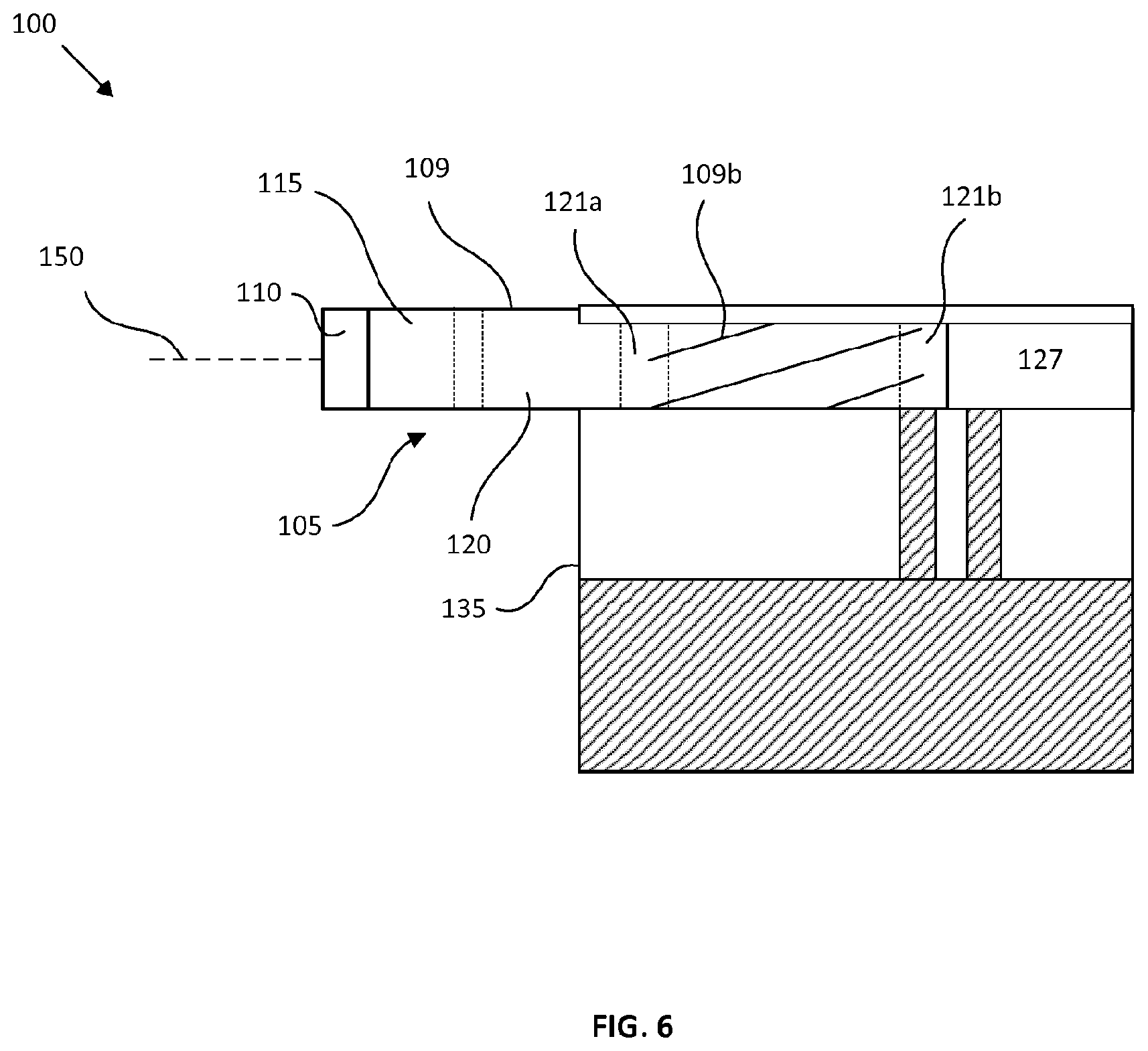
[0033] FIG. 6 is a schematic diagram of a partially wrapped inner tubular element.
[0034] The schematic drawings are not necessarily to scale and are presented for purposes of illustration and not limitation. The drawings depict one or more aspects described in this disclosure. However, it will be understood that other aspects not depicted in the drawings fall within the scope of this disclosure.
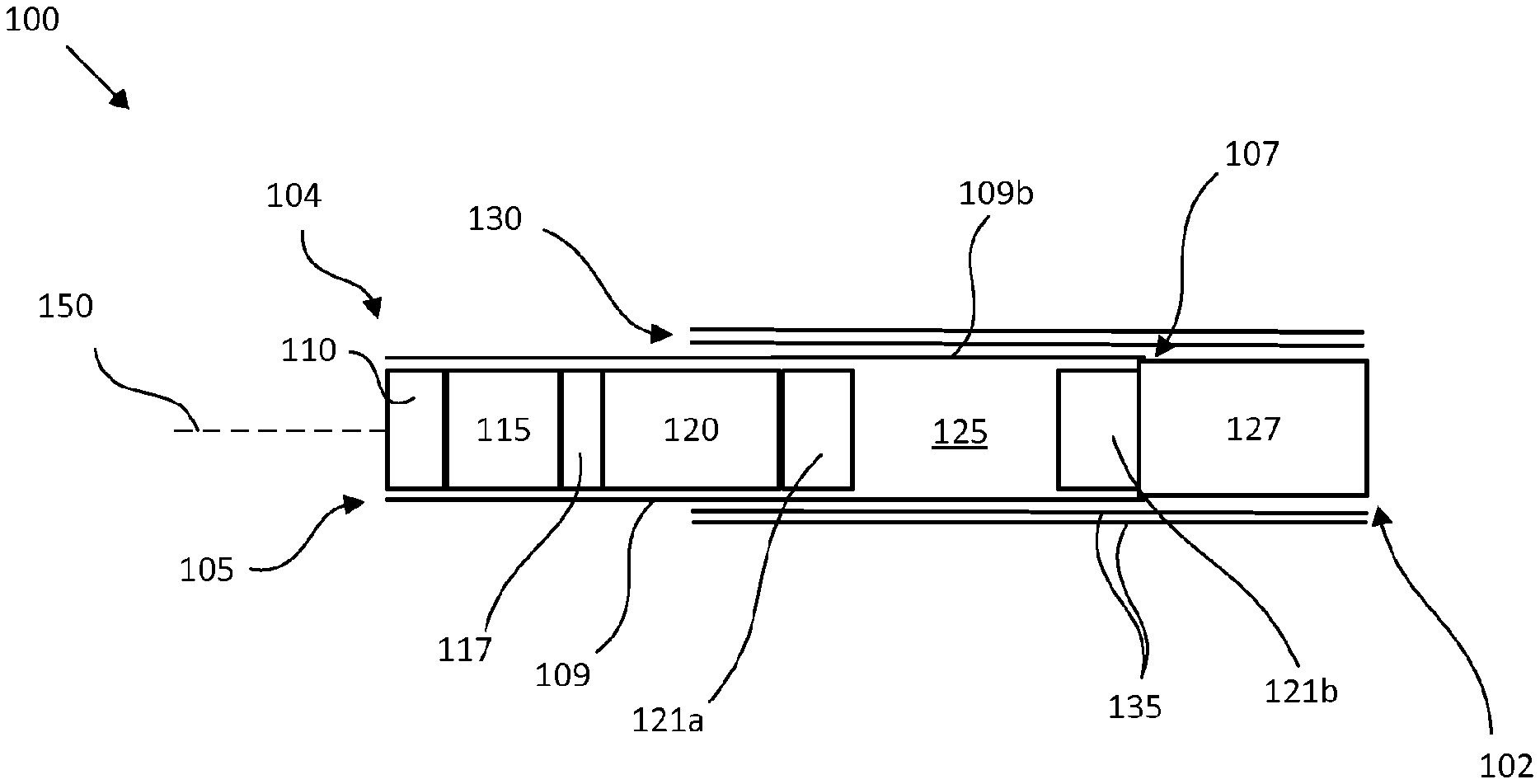
[0035] FIG. 1 is a schematic diagram of an exemplary aerosol generating article 100 extending between a proximal end 102 and a distal end 104. An inner tubular element 105 having a mouthpiece end 107 is provided in the aerosol generating article 100. Also provided is an opposed heat source end positioned at the distal end 104 of the aerosol generating article 100. The inner tubular element 105 comprises an inner wrapping sheet 109. The inner wrapping sheet 109 circumscribes a combustible heat source 115 positioned towards the distal end of the aerosol generating article 100. The inner wrapping sheet 109 further circumscribes an aerosol-forming substrate 120 positioned downstream of the combustible heat source 115. The inner wrapping sheet 109 further circumscribes a void space 125 located between the aerosol-forming substrate 120 and the mouthpiece end 107. The combustible heat source 115, aerosol-forming substrate 120 and void space 125 are provided in a co-axial arrangement. The aerosol generating article 100 further comprises an outer tubular element 130 extending from the proximal end 102 of the aerosol generating article 100 towards the distal end 104 thereof. The outer tubular element 130 circumscribes at least the mouthpiece end 107 of the inner tubular element 105 and the void space 125. The outer tubular element 130 terminates downstream of the heat source 115. The inner wrapping sheet 109 includes a pre-twisted portion 109b in at least in the region circumscribing the void space 125 (see FIG. 6). The distal end 104 including the combustible heat source 115 and the aerosol-forming substrate 120 is slideable relative to the outer tubular element 130 from an extended position having a first article length (L1, see FIG. 2A), to a retracted position having a second article length less than the first article length (L2, see FIG. 2B). Sliding the distal end 104 from an extended position to a retracted position at least partially collapses the void space 125 to an axially contracted configuration.
[0036] The aerosol generating article 100 is also shown comprising first 121a and second 121b transfer elements located within the inner tubular element 105 (see FIG. 2A). The first 121a and second 121b transfer elements may be spaced from one another when the aerosol generating article is in the extended position. The first 121a and second 121b transfer elements are shown located at the ends of the void space 125, between the aerosol-forming substrate 120 and the mouthpiece filter 127 respectively. The aerosol generating article 100 is also shown comprising a transfer element 117 located between the combustible heat source 115 and the aerosol-forming substrate 120. The transfer element 117 is circumscribed within the inner wrapping sheet 109.
[0037] As shown in FIG. 6, the pre-twisted portion 109b of the inner wrapping sheet 109 may circumscribe part of respective first 121a and second 121b transfer elements. To extinguish the combustible heat source 115, the distal end 104 including the combustible heat source 115 and the aerosol-forming substrate 120 is slideable relative to the outer tubular element 130. The distal end is slideable from an extended position having a first article length (L1 in FIG. 2A), to a retracted position having a second article length (L2 in FIG. 2B) less than the first article length, as shown in FIG. 2A and 2B. In the retracted position, the void space 125 is at least partially collapsed to an axially contracted configuration. The axially contracted configuration may be caused by application of a pressure or force at the distal end of the aerosol generating article 100, such as when an aerosol generating article 100 is "stubbed out". It is not essential that the void space 125 be entirely collapsed. While the transfer elements 121a, 121b are separated in the extended position, in some cases it may be desirable to keep the transfer elements 121a, 121b separated when the aerosol generating article 100 is in the contracted position, such as shown in FIG. 2B. In other cases, it may be desirable that the first 121a and second 121b transfer elements abut one another when the void space 125 is collapsed to the axially contracted configuration (not shown). It would be apparent to the skilled person that the first 121a and second 121b transfer elements are not essential features; for example, the void space may be bounded distally by the aerosol-forming substrate 120, and proximally by the mouthpiece filter 127. Indeed, the void space 125 itself is not essential. It will be understood that any axially compressible structure within the inner tubular element would enable the distal end of the inner tubular element to be slideable relative to the outer tubular element for "stubbing out" the aerosol generating article 100.
[0038] The pre-twisted portion 109b is a preferred method of creating an area of weakness, to enable the distal end of the inner tubular element to be slideable relative to the outer tubular element, in particular over perforating or cutting slits into the inner wrapping sheet, as the pre-twisted portion does not introduce additional air paths within the aerosol generating article 100. Preferably, aerosol generating articles 100 are manufactured on a back-to-back basis, such as shown in FIGS. 3 and 4. That is to say, two aerosol generating articles 100, 100' are created integrally and simultaneously before being separated by cutting through the conjoined articles centrally. FIG. 3 illustrates first 105 and second 105' inner tubular elements before being overwrapped by an outer wrapping sheet 135. In the back-to-back configuration, a single mouthpiece filter element 129 can be considered to have first and second ends which correspond to initially conjoined first 127 and second 127' mouthpiece filters which are mounted to the respective proximal ends 102, 102' of first 105 and second 105' inner tubular elements. The first 127 and second 127' mouthpiece filters are located downstream of the respective associated void space 125, 125'. This advantageously allows for simultaneous overwrapping of the first 105 and second 105' inner tubular elements using a single outer wrapping sheet comprising initially conjoined outer wrapping sheets 135, 135' that are symmetric about the centre line 200 of the mouthpiece filter element 129 to form initially conjoined first 130 and second 130' outer tubular elements. Once formed, the conjoined aerosol generating articles 100, 100' can be separated by cutting through the conjoined outer tubular elements 130, 130' and the mouthpiece filter element 129.
[0039] The co-axial arrangement of the inner tubular element 105 is best shown in FIG. 1. Inner tubular element 105 has a mouthpiece end 107 and a heat source end and comprises an inner wrapping sheet 109 circumscribing, in a co-axial arrangement, a combustible heat source 115 positioned towards the distal end 104 of the aerosol generating article 100; an aerosol-forming substrate 120 downstream of the combustible heat source 115 and a void space 125 between the aerosol-forming substrate 120 and the mouthpiece end 107. The inner wrapping sheet 109 includes a pre-twisted portion 109b at least in the region circumscribing the void space 125. The inner tubular element 105 is also shown comprising a cap 110 at the distal end 104, upstream of the combustible heat source 115. The cap 110 is shown abutting the combustible heat source 115 and is circumscribed by a portion of the inner wrapping sheet 109. The removable cap 110 may comprise a desiccant, such as glycerine, to absorb moisture. This prolongs the longevity of the components within the inner tubular element 105. The removable cap 110 may be removed by twisting the removable cap 110 to break the portion of the inner wrapping sheet 109 adjacent to the cap. Removal of the removeable cap 110 exposes a front portion of the combustible heat source 115 enabling the ignition the combustible heat source 115. The combustible heat source 115 may be a carbonaceous heat source. The aerosol- forming substrate 120 may comprise tobacco.
[0040] The outer wrapping sheet 135 comprises first 155a and second 155b opposed edges, substantially parallel with a longitudinal axis 150 of the aerosol generating article 100. The longitudinal axis 150 of the aerosol generating article 100 extends between the proximal 102 and distal 104 ends of the aerosol generating article 100. The first 155a and second 155b opposed edges define therebetween a width of the outer wrapping sheet 135. The width of the outer wrapping sheet 135 is at least equal to twice the circumference of an inner tubular element 105 that it is to circumscribe so that it can wrap around at least twice. Extending perpendicularly between the first 155a and second 155b edges are the proximal 102 and distal 103 ends of the outer wrapping sheet 135. It will be understood that when a pair of aerosol generating articles 100 are manufactured back-to-back with an initially conjoined outer wrapping sheet, that the respective proximal ends 102, 102' will be conjoined at the centre line 200. For simplicity, the remaining description will be in respect of the outer wrapping sheet 135 only. The outer wrapping sheet 135' is an identical mirror image and like parts are referenced by like reference signs, but suffixed with a prime (').
[0041] The outer wrapping sheet 135 is shown having an exemplary glue pattern. The glue pattern shown in FIG. 3 comprises a band of glue in the form of first 145a and second 145b strips of glue extending substantially perpendicularly from the first edge 155a towards the second edge 155b for at least a distance equal to the circumference of the inner tubular element 105. The first strip of glue 145a forms an adhesive join between the outer wrapping sheet 135 and the inner tubular element 105, in the region of and circumscribing the second transfer element 121b. The adhesive join is thus formed only at the mouthpiece end 107 thereof when wrapped therearound starting from the first edge 155a. The second strip of glue 145b, similar to the first strip 145a, but more proximally located, is used to join the outer wrapping sheet 135 to a mouthpiece filter 127. The first 145a and second 145b strips form a band of glue that allows the outer wrapping sheet 135 to be bonded to the inner tubular element 105 and mouthpiece filter 127 only at the mouthpiece end 107. While two discrete strips 145a, 145b are shown, it would be appreciated that other glue arrangements, such as a single strip and non-continuous droplets or lines are included by this description.
[0042] The glue pattern is shown further comprising a second region comprising an area of glue 140 extending along substantially the whole length of the outer wrapping sheet 135 (i.e. from the proximal end 102 to the distal end 103), from the point at which the band 145a, 145b ends to the second edge 155b. The area of glue 140 forms an adhesive join between the first wrap and any subsequent wraps of the outer wrapping sheet 135 along substantially the whole length thereof. While adhesives are described, other methods in the art of joining the outer tubular element 130 to the inner tubular element 105 or to itself are included in this description. For example, perforations between the sheets or use of tightening bands may be similarly effective.
[0043] While the outer tubular element 130 of the aerosol generating article is shown terminating downstream of the aerosol-forming substrate 120, it would be apparent to the skilled person that such an arrangement is purely exemplary and that arrangements where the outer tubular element 130 terminated at the aerosol-forming substrate 120 would be equally included by this description.
[0044] The aerosol generating article 100 may have a length and diameter similar to a conventional cigarette. The second article length, L2, may be about 90% or less than the first article length. The second article length may be about 80% or less than the first article length. The second article length may be about 70% or less than the first article length.
[0045] The pre-twisted portion 109b of the inner tubular element 105 may comprise a rotational offset between a portion of the inner tubular element upstream of the pre-twisted portion 109b (subsequently referred to as the "upstream portion") and a portion of the inner tubular element downstream of the pre-twisted portion (subsequently referred to as the "downstream portion"). The rotational offset between the upstream and downstream portions of the inner tubular element may be about 5 degrees or more. The rotational offset between the upstream and downstream portions of the inner tubular element may be about 15 degrees or more. The rotational offset between the upstream and downstream portions of the inner tubular element may be about 45 degrees or more. The pre-twisted portion can be identified by a series of helical grooves and depressions formed in the inner wrapping sheet circumferentially disposed about the inner tubular member. When unwrapped, the series of helical grooves and depressions would comprise a corresponding series of substantially parallel diagonal lines in the inner wrapping sheet.
[0046] FIG. 5 is a side view of the manufacturing station used to apply the pre-twisted portion 109b. The overwrapping station illustrated comprises a first rotating drum 220, on which a series of outer wrapping sheets 135 with the glue pattern applied is temporarily attached, for example by the application of a vacuum holding an unglued side of each sheet 135 to an outer surface of the first rotating drum 220. Each outer wrapping sheet 135 is adhered, at the first edge 155a thereof, to an inner tubular element 105. As the first rotating drum 220 rotates, each inner tubular element 105 is brought, with outer wrapping sheet 135 attached, in turn towards a stationary guide plate 230. The first rotating drum 220 and stationary guide plate 230 act as a pinch 210 and friction between the unwrapped aerosol generating article, stationary guide plate 230 and first rotating drum 220 cause the outer wrapping sheet 135 to wrap around the inner tubular element 105 thereby forming a wrapped aerosol generating article 100.
[0047] The glue pattern shown in FIG. 3 enables the outer wrapping sheet 135 to adhere to the inner tubular element 105 and the mouthpiece filter 127 in a first circumferential wrap. As the outer wrapping sheet 135 wraps around the inner tubular element 105, the band of glue comprising first 145a and second 145b strips of glue bond the outer wrapping sheet 135 to the mouthpiece filter 127 and the inner tubular element 105 at the mouthpiece end 107. As the upstream portion of the inner tubular element 105 is not overwrapped--because the distal end 103 of the outer wrapping sheet 135 terminates more proximally--it rotates at a different rate to the downstream portion of the inner tubular element 105, which induces the twist in the inner wrapping sheet 109 of the inner tubular element 105. The difference in thickness between the portions of the inner tubular element 105 that are circumscribed by the outer wrapping sheet 135 and those portions that are not generates different amounts of friction. This difference in friction causes the portion of the inner tubular element without any outer wrapping sheet 135 wrapped around to rotate less than the portion that is circumscribed by the outer wrapping sheet 135, thus creating the pre-twisted portion 109b that is readily collapsible.
[0048] Once the desired amount of twist has been achieved, the outer wrapping sheet 135 wraps around the inner tubular element 105 for a second circumferential wrap. During the second circumferential wrap, the outer wrapping sheet 135 is wrapped around the unglued portion of the inner tubular element 105. The second region 140 of glue results in the second circumferential wrap of the outer wrapping sheet 135 forming an outer tubular element 130 that is rigid, but remains readily collapsible.
[0049] After the outer wrapping sheet 135 has circumscribed itself a second time, the aerosol generating article 100 is formed and may be removed from the pinch 210 by a second rotating drum 240. While it is preferable to apply the pre-twist to the inner tubular element 105 simultaneously when overwrapping the inner tubular element 105, it would be apparent to the skilled person this is not essential. The pre-twist may be applied at a twisting station prior to the overwrapping station.
[0050] While the manufacturing process has been described in the context of a single aerosol generating article 100, it would be apparent to the skilled person that this description would apply mutatis mutandis to aerosol generating articles manufactured in the back-to-back configuration, which may be preferable for process efficiency, being able to produce two articles 100, 100' simultaneously within a single manufacture line. When manufacturing aerosol generating articles in the back-to-back configuration, the rolled article that is removed from the pinch 210 by the second rotating drum 240 will comprise conjoined outer tubular elements 130, 130'. In this case, the rolled article can be divided along the centre line 200 by cutting through the conjoined outer tubular elements 130, 130' and conjoined mouthpiece filter member 129 to result in first 100 and second 100' aerosol generating articles. This cutting procedure can be performed as part of the overwrapping process, or at a separate cutting station.
[0051] While a mouthpiece filter 127 and mouthpiece filter member 129 have been included in this description, they are not essential to the present invention. Similarly, while a removeable cap 110 has been described as a way of preserving the aerosol-forming substrate, a removeable cap 110 is not essential to the present invention. Similarly, while a transfer element 117 has been described, it is not essential to the present invention. Further, while the pre-twisted portion 109b has been described as preferably formed simultaneously during the overwrapping of the inner tubular element 105, this is not essential to the invention. The pre-twisted portion 109b of the inner wrapping sheet 109 may be applied at a separate twisting station and subsequently overwrapped. While an adhesive has been described as a method of securing the outer wrapping sheet 135 to the inner tubular element 105 and to itself, this is not essential to the invention and other methods of fixation, including methods of mechanical fixation such as perforations or surface features, are included in this description. While the outer wrapping sheet 135 is described as being adhered to itself along substantially the whole length of the outer wrapping sheet 135, this is not essential to the invention. Adhesion along less than the whole length of the outer wrapping sheet 135 may still provide the benefit of the invention.
[0052] Features, integers, characteristics, compounds, chemical moieties or groups described in conjunction with a particular aspect, embodiment or example of the invention are to be understood to be applicable to any other aspect, embodiment or example described herein unless incompatible therewith. All of the features disclosed in this specification (including any accompanying claims, abstract and drawings), and/or all of the steps of any method or process so disclosed, may be combined in any combination, except combinations where at least some of such features and/or steps are mutually exclusive. The invention is not restricted to the details of any foregoing embodiments. The invention extends to any novel one, or any novel combination, of the features disclosed in this specification (including any accompanying claims, abstract and drawings), or to any novel one, or any novel combination, of the steps of any method or process so disclosed.
* * * * *
D00000
D00001
D00002
D00003
D00004
D00005
D00006
XML
uspto.report is an independent third-party trademark research tool that is not affiliated, endorsed, or sponsored by the United States Patent and Trademark Office (USPTO) or any other governmental organization. The information provided by uspto.report is based on publicly available data at the time of writing and is intended for informational purposes only.
While we strive to provide accurate and up-to-date information, we do not guarantee the accuracy, completeness, reliability, or suitability of the information displayed on this site. The use of this site is at your own risk. Any reliance you place on such information is therefore strictly at your own risk.
All official trademark data, including owner information, should be verified by visiting the official USPTO website at www.uspto.gov. This site is not intended to replace professional legal advice and should not be used as a substitute for consulting with a legal professional who is knowledgeable about trademark law.