Apparatus, Systems And Methods For Steerable Toolbars
Barry; Alan F. ; et al.
U.S. patent application number 16/997361 was filed with the patent office on 2021-02-25 for apparatus, systems and methods for steerable toolbars. The applicant listed for this patent is Ag Leader Technology. Invention is credited to Alan F. Barry, Jacob Christensen, Loren Leusink, Kurt Townsend.
| Application Number | 20210051837 16/997361 |
| Document ID | / |
| Family ID | 1000005197870 |
| Filed Date | 2021-02-25 |


View All Diagrams
| United States Patent Application | 20210051837 |
| Kind Code | A1 |
| Barry; Alan F. ; et al. | February 25, 2021 |
Apparatus, Systems And Methods For Steerable Toolbars
Abstract
The disclosed apparatus, systems and methods relate to a steerable toolbar. The toolbar is able to rotate relative to the tractor or other driving vehicle to reduce misalignment and/or cross-track error. Actuators can be utilized with draft links to pivot the toolbar around a central pivot point and improve the following path of the toolbar implement.
| Inventors: | Barry; Alan F.; (Nevada, IA) ; Leusink; Loren; (Ames, IA) ; Christensen; Jacob; (Ames, IA) ; Townsend; Kurt; (Ames, IA) | ||||||||||
| Applicant: |
|
||||||||||
|---|---|---|---|---|---|---|---|---|---|---|---|
| Family ID: | 1000005197870 | ||||||||||
| Appl. No.: | 16/997361 | ||||||||||
| Filed: | August 19, 2020 |
Related U.S. Patent Documents
| Application Number | Filing Date | Patent Number | ||
|---|---|---|---|---|
| 62888615 | Aug 19, 2019 | |||
| Current U.S. Class: | 1/1 |
| Current CPC Class: | A01B 59/004 20130101; A01B 59/042 20130101; A01B 73/065 20130101; A01B 69/006 20130101; A01B 69/004 20130101 |
| International Class: | A01B 69/08 20060101 A01B069/08; A01B 69/00 20060101 A01B069/00; A01B 59/00 20060101 A01B059/00; A01B 73/06 20060101 A01B073/06 |
Claims
1. A steerable toolbar system, comprising: (a) a steerable implement comprising: (i) a toolbar in operable communication with a hitch; (ii) at least one link extending between the hitch and the toolbar; (iii) at least one actuator in communication with the at least one link; and (iv) a pivot disposed at a connection point between the hitch and the toolbar; and (b) a controller in electronic communication with the at least one actuator, wherein the controller is configured to adjust the angle of the toolbar relative to the hitch via the at least one actuator.
2. The system of claim 1, wherein the at least one link is a telescoping link having an extended position and a retracted position.
3. The system of claim 2, wherein the at least one link is urged between the extended and retracted positions via the at least one actuator.
4. The system of claim 1, wherein the toolbar rotates about the pivot in response actuation of the at least one link.
5. The system of claim 1, further comprising a hitch position sensor in electronic communication with the controller, wherein the hitch position sensor is constructed and arranged to send signals to the controller about the position of the hitch.
6. The system of claim 1, further comprising two fold hinges constructed and arranged such that the toolbar can be folded to be substantially parallel to the hitch.
7. The system of claim 1, wherein the controller is in further communication with a guidance system.
8. An agricultural implement comprising: (a) a toolbar comprising: (i) a pin and (ii) at least one ground engaging tool; (b) an elongate attachment, a first end of the elongate attachment attached to the toolbar via the pin; (c) a first draft link extending between a second end of the elongate attachment and the toolbar; (d) a first actuator in operable communication with the first draft link, wherein actuation of the first draft link via the first actuator adjusts the angle of the toolbar relative to the elongate attachment; and (e) a controller in electronic communication with the first actuator.
9. The agricultural implement of claim 8, further comprising a position receiver disposed on the implement.
10. The agricultural implement of claim 8, further comprising a hitch position sensor disposed on a hitch.
11. The agricultural implement of claim 8, wherein the controller is in further communication with a guidance system.
12. The agricultural implement of claim 8, further comprising: (a) a second draft link extending between the second end of the elongate attachment and the toolbar and (b) a second actuator in operable communication with the second draft link, wherein actuation of the second draft link via the second actuator adjusts the angle of the toolbar relative to the elongate attachment.
13. The agricultural implement of claim 8, further comprising a first hinge positioned on the toolbar on a first side of the pin and a second hinge positioned on the toolbar on a second side of the pin.
14. The agricultural implement of claim 13, wherein the toolbar is configured to fold inward at the first and second hinges into a compact configuration.
15. A method for steering an agricultural implement comprising: determining a guidance path on a controller; traversing the guidance path via a vehicle, the vehicle attached to the agricultural implement, the agricultural implement comprising an elongate bar and a hitch; adjusting the angle of the elongate bar relative to the hitch such that the agricultural implement traverses the guidance path with path fidelity.
16. The method of claim 15, further comprising storing the guidance path traveled for use in subsequent operations.
17. The method of claim 15, wherein the angle of the elongate bar is adjusted on-the-go.
18. The method of claim 15, further comprising sensing the position of the agricultural implement via at least one position sensor.
19. The method of claim 15, further comprising mapping exact locations of the vehicle and the agricultural implement during operation.
20. The method of claim 15, wherein the vehicle is a tractor and the implement is a planter.
Description
CROSS-REFERENCE TO RELATED APPLICATION(S)
[0001] This application claims the benefit under 35 U.S.C. .sctn. 119(e) to U.S. Provisional Application 62/888,615, filed Aug. 19, 2019, and entitled "Apparatus, Systems And Methods For Steerable Toolbars," which is hereby incorporated herein by reference in its entirety for all purposes.
TECHNICAL FIELD
[0002] The disclosed technology relates generally to a steerable toolbar system and in particular, to the devices, methods, and design principles allowing an implement being towed by a tractor to follow an identical path to the tractor via use of the steerable toolbar.
BACKGROUND
[0003] The disclosure relates to apparatus, systems and methods for a steerable toolbar system that enables agricultural implements to follow an identical path to the pulling tractor.
[0004] Current designs are intended to cause a toolbar to more closely track the same path as the pulling tractor. One way is to add on attachments to force the implement in one direction or the other. Another is by shifting the tractor drawbar to one side or the other to compensate for off path tracking. Yet another is by attempting to predict the amount of correction to be made by the pulling tractor and applying that amount to the tractor guidance path.
[0005] This method will build steerable functionality into the toolbar design and use working ground engagement tools to steer the implement to the desired path. A centrally located hinge pin is built into the design of the toolbar and guidance information is used to steer the toolbar relative to the center hitch so the ground engaging tools mounted on the implement cause the machine to guide right or left as it is drawn across a field. This will result in more accurate results, more responsiveness in the guidance system, less stress on the toolbar and the ground engaging tools.
[0006] This design will reduce or eliminate side load stress on ground engaging tools because the pull line is always perpendicular to the toolbar.
BRIEF SUMMARY
[0007] Discussed herein are various devices, systems and methods relating to a toolbar type implement designed to be pulled forward by a tractor and used to fertilize, plant, cultivate, etc. The toolbar machine design includes a hinge and actuators that cause it to change the angle of the toolbar section relative to the hitch section. This is then used to steer the implement as it is drawn forward using the ground engaging tools attached to the toolbar to react against the soil to counter act the effects of side hill draft and corner turns that are common with current state of the art implements. The disclosed implementations relate to both the construction of the toolbar and the overlaying control method. It will be appreciated that there are several types of position sensing methods that could be used to provide input to the control system. These could include, but are not limited to; a position receiver located on the implement, a relative hitch position sensor tied to the tractor and implement hitch, a control method that predicts the expected error to be corrected based on known factors such as turning rate, slope angle, speed and the link, or a system that measures the position of the implement as compared to the tractor.
[0008] A system of one or more computers can be configured to perform particular operations or actions by virtue of having software, firmware, hardware, or a combination of them installed on the system that in operation causes or cause the system to perform the actions. One or more computer programs can be configured to perform particular operations or actions by virtue of including instructions that, when executed by data processing apparatus, cause the apparatus to perform the actions. Implementations of the described techniques may include hardware, a method or process, or computer software on a computer-accessible medium.
[0009] In Example 1, a steerable toolbar system, comprising a steerable implement comprising a toolbar in operable communication with a hitch, at least one link extending between the hitch and the toolbar, at least one actuator in communication with the at least one link, and a pivot disposed at a connection point between the hitch and the toolbar, and a controller in electronic communication with the at least one actuator, wherein the controller is configured to adjust the angle of the toolbar relative to the hitch via the at least one actuator.
[0010] In Example 2, the system of Example 1, wherein the at least one link is a telescoping link having an extended position and a retracted position.
[0011] In Example 3, the system of Example 2, wherein the at least one link is urged between the extended and retracted positions via the at least one actuator.
[0012] In Example 4, the system of Example 1, wherein the toolbar rotates about the pivot in response actuation of the at least one link.
[0013] In Example 5, the system of Example 1, further comprising a hitch position sensor in electronic communication with the controller, wherein the hitch position sensor is constructed and arranged to send signals to the controller about the position of the hitch.
[0014] In Example 6, the system of Example 1, further comprising two fold hinges constructed and arranged such that the toolbar can be folded to be substantially parallel to the hitch.
[0015] In Example 7, the system of Example 1, wherein the controller is in further communication with a guidance system.
[0016] In Example 8, an agricultural implement comprising a toolbar comprising a pin and at least one ground engaging tool, an elongate attachment, a first end of the elongate attachment attached to the toolbar via the pin, a first draft link extending between a second end of the elongate attachment and the toolbar, a first actuator in operable communication with the first draft link, wherein actuation of the first draft link via the first actuator adjusts the angle of the toolbar relative to the elongate attachment, and a controller in electronic communication with the first actuator.
[0017] In Example 9, the agricultural implement of Example 8, further comprising a position receiver disposed on the implement.
[0018] In Example 10, the agricultural implement of Example 8, further comprising a hitch position sensor disposed on a hitch.
[0019] In Example 11, the agricultural implement of Example 8, wherein the controller is in further communication with a guidance system.
[0020] In Example 12, the agricultural implement of Example 8, further comprising a second draft link extending between the second end of the elongate attachment and the toolbar and a second actuator in operable communication with the second draft link, wherein actuation of the second draft link via the second actuator adjusts the angle of the toolbar relative to the elongate attachment.
[0021] In Example 13, the agricultural implement of Example 8, further comprising a first hinge positioned on the toolbar on a first side of the pin and a second hinge positioned on toolbar on a second side of the pin.
[0022] In Example 14, the agricultural implement of Example 13, wherein the toolbar is configured to fold inward at the first and second hinges into a compact configuration.
[0023] In Example 15, a method for steering an agricultural implement comprising determining a guidance path on a controller, traversing the guidance path via a vehicle, the vehicle attached to the agricultural implement, the agricultural implement comprising an elongate bar and a hitch, adjusting the angle of the elongate bar relative to the hitch such that the agricultural implement traverses the guidance path with path fidelity.
[0024] In Example 16, the method of Example 15, further comprising storing the guidance path traveled for use in subsequent operations.
[0025] In Example 17, the method of Example 15, wherein the angle of the elongate bar is adjusted on-the-go.
[0026] In Example 18, the method of Example 15, further comprising sensing the position of the agricultural implement via at least one position sensor.
[0027] In Example 19, the method of Example 15, further comprising mapping exact locations of the vehicle and the agricultural implement during operation.
[0028] In Example 20, the method of Example 15, wherein the vehicle is a tractor and the implement is a planter.
[0029] While multiple embodiments are disclosed, still other embodiments of the disclosure will become apparent to those skilled in the art from the following detailed description, which shows and describes illustrative embodiments of the disclosed apparatus, systems and methods. As will be realized, the disclosed apparatus, systems and methods are capable of modifications in various obvious aspects, all without departing from the spirit and scope of the disclosure. Accordingly, the drawings and detailed description are to be regarded as illustrative in nature and not restrictive.
BRIEF DESCRIPTION OF THE DRAWINGS
[0030] FIG. 1 is a top view of a prior art toolbar.
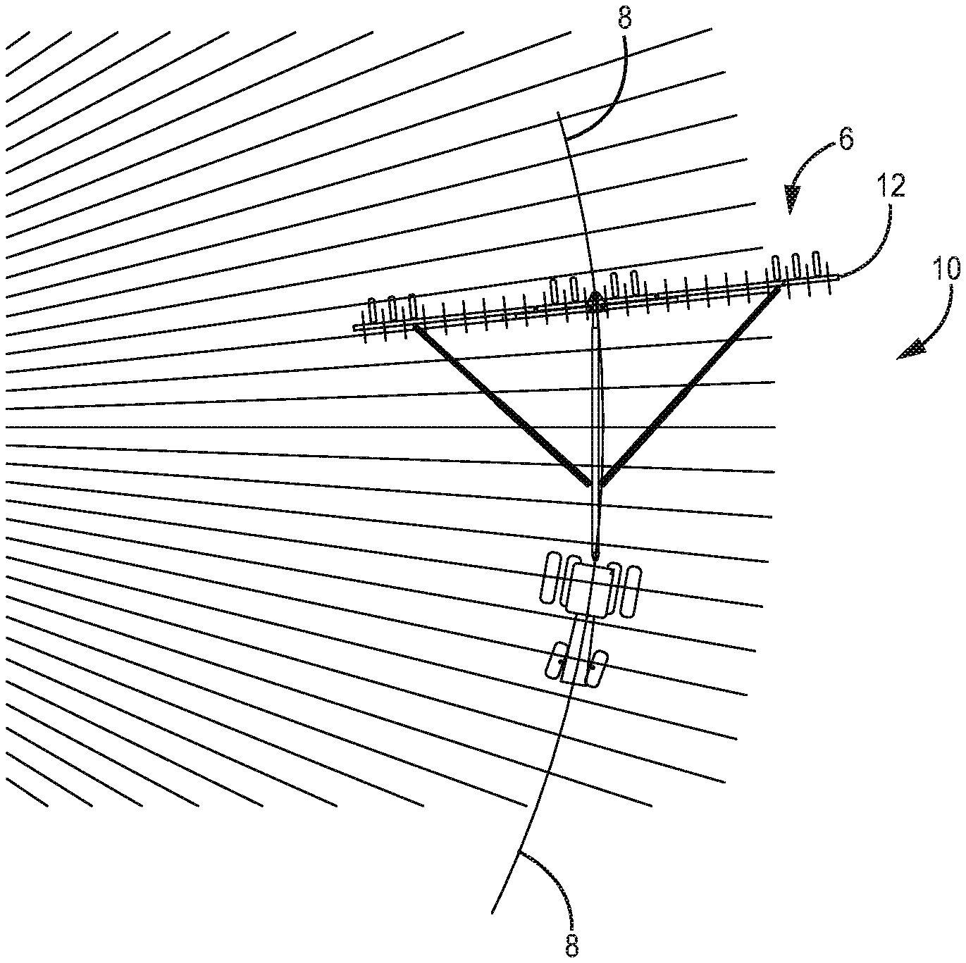
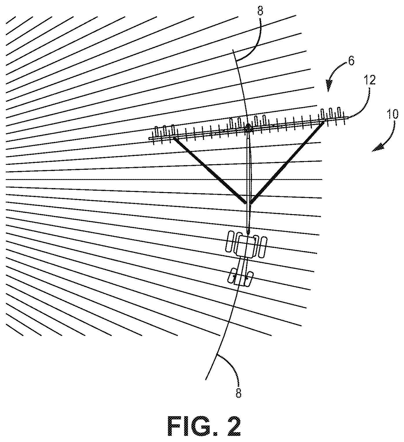
[0031] FIG. 2 is a top view of a steerable toolbar system, according to one implementation.
[0032] FIG. 3A is a top view of a steerable toolbar system, according to one implementation.
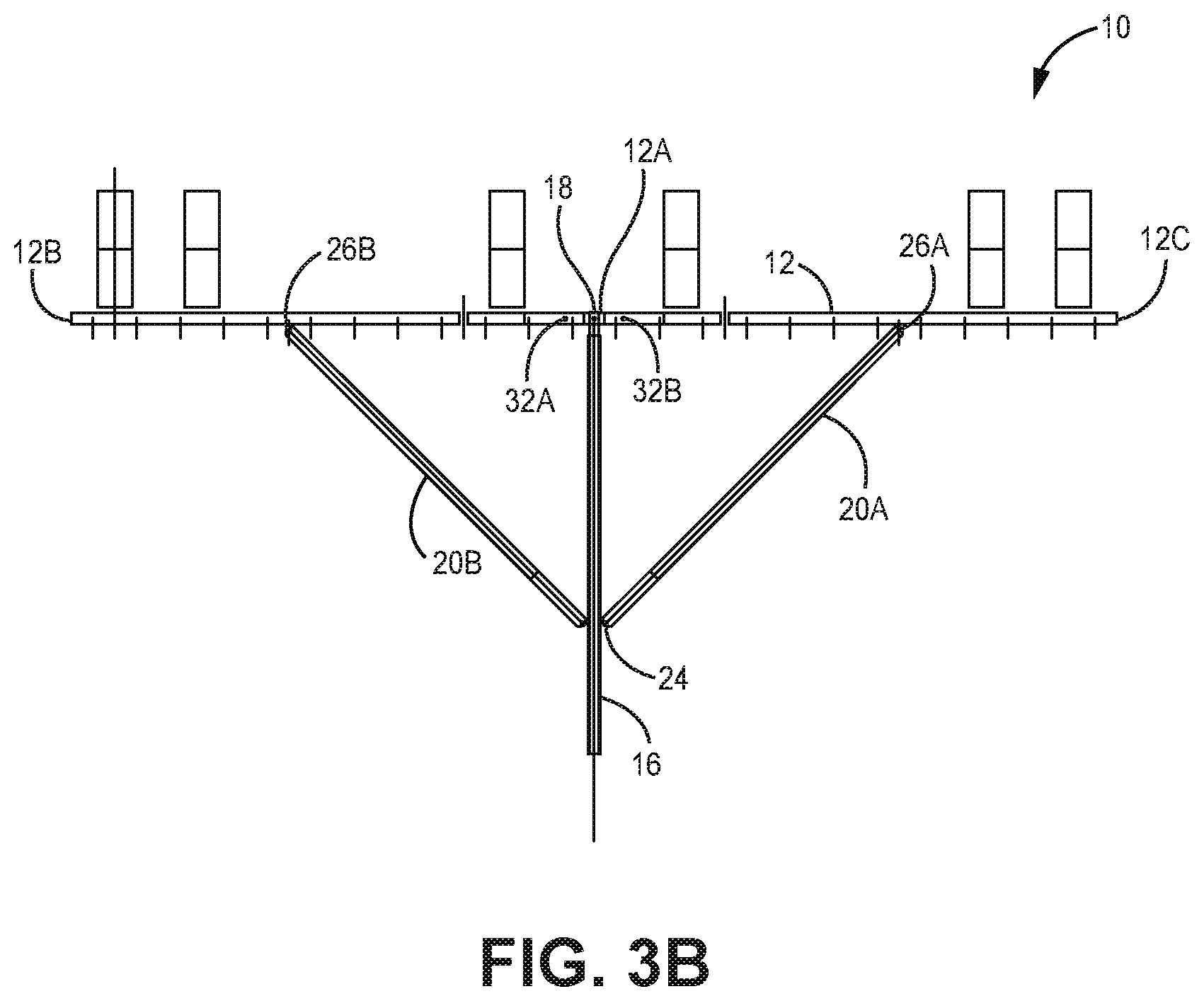
[0033] FIG. 3B is a top view of a steerable toolbar system, according to one implementation.
[0034] FIG. 4A is a side perspective view of a steerable toolbar system, according to one implementation.
[0035] FIG. 4B is a top view of a steerable toolbar system, according to one implementation.
[0036] FIG. 4C is a top view of a steerable toolbar system, according to one implementation.
[0037] FIG. 4D is a process diagram for a steerable toolbar system, according to one implementation.
[0038] FIG. 4E is a top view of a steerable toolbar system, according to one implementation.
[0039] FIG. 4F is a process diagram for a steerable toolbar system, according to one implementation.
[0040] FIG. 5 is a top view of a steerable tool bar, according to one implementation.
[0041] FIG. 6 is a top view of a steerable toolbar, according to one implementation.
[0042] FIG. 7 top view of a steerable toolbar, according to one implementation.
[0043] FIG. 8 top view of a steerable toolbar, according to one implementation.
[0044] FIG. 9 is a top view of a steerable toolbar system in a compact configuration, according to one implementation.
[0045] FIG. 10 is a top view of a steerable toolbar system in a compact configuration, according to one implementation.
DETAILED DESCRIPTION
[0046] The various embodiments disclosed or contemplated herein relate to a steerable toolbar for use in agricultural implementations. In various implementations, the steerable toolbar described herein is utilized in conjunction with a variety of agricultural operations, such as in conjunction with fertilizer applicators, planters, cultivators and the like, as would be readily appreciated. In various implementations, the steerable toolbar system utilizes a plurality of telescopic draft links and associated actuators for movement of the steerable toolbar.
[0047] It is appreciated that the various technologies described herein can be used in conjunction with any of the innovations disclosed in co-pending U.S. application Ser. No. 16/939,785, filed Jul. 27, 2020 and U.S. application Ser. No. 16/921,828, filed Jul. 6, 2020.
[0048] Turning to the drawings in greater detail, as is shown in FIG. 1, large toolbar-type implements 2, particularly with relatively long trailing distances behind tractors 4, may follow a different path (shown generally at 5) around corners and when operated on side hills or other environments. That is, both the heading and/or centerline of toolbar-type implements 2 are not necessarily aligned with those of the tractor 4 or other implement pulling them, as is readily understood. Accordingly, there can be discrepancies between the path traversed by the tractor 4 and toolbar 2.
[0049] Further, when the side draft from ground engaging tools mounted to the toolbar 2 is unbalanced between the sides, the toolbar 2 can draft off the path 8 of the pulling tractor 4. Even when optional tractor 4 steering guidance is used, this drafting can have a detrimental effect on the accuracy of the tractor's guidance system for toolbar 2 placement, as is also understood from the references incorporated herein.
[0050] As such, the various implementations of the steerable toolbar system 10 disclosed herein and shown in FIGS. 2-11B relate to a practical steering control solution for use in conjunction with fertilizer applicators, planters, cultivators and the like so as to maintain a consistent path 6 for the toolbar 12 that aligns with the path 8 of the tractor 4. Further implementations will be apparent to those of skill in the art.
[0051] As shown in FIGS. 3A-4B, in exemplary implementations the steerable toolbar system 10 has a toolbar 12 capable of being disposed on a hitch 16 that is connected to a tractor drawbar with a vertical pin (not shown) so as to allow movement of the hitch 16. At the distal or rear end of the hitch 16, a steerable attachment point 18 connects the hitch 16 to the toolbar 12. In these implementations, the attachment point 18 is a vertical pivot, but in alternate implementations, other types of steerable attachments could be conceived to create the same controlled steering effect such as a side shifting mechanism. Further, in certain implementations, the hitch 16 is optionally an elongate, telescoping hitch 16.
[0052] In the implementations of FIGS. 3A-4B, telescoping, elongate draft links 20A, 20B project diagonally rearward from an approximate midpoint 24 on the hitch 16 to an anchoring point 26A, 26B on the toolbar 12, that in certain implementations are generally equally spaced between the center 12A and the ends 12B, 12C of the toolbar 12. However, it is understood that exact equal spacing of the anchoring points 26A, 26B on the draft links 20A, 20B is not critical to the design and should not be considered a requirement. It is further understood that the draft links 20A, 20B are constructed to telescope and retract from a nominal length position.
[0053] In various implementations, a position sensor 28, or various position sensors 28A, 28B, 28C, collects data about the positioning or path of the toolbar 12. The control system 34 or steering computer 34 uses the data of the position of the toolbar 12 relative to the path 8 of the tractor 4 to adjust the angle of the toolbar 12 relative to the hitch 16 to maintain alignment. Therefore, the control system 34 uses data from the position sensor 28 to engage linear actuators 22 to telescope and retract the draft links 20A, 20B as needed to modify the path of the toolbar 12.
[0054] As shown in FIG. 4A-4D, control of the telescoping and retracting function can be effectuated via a linear actuator 22 or other similar mechanism in operational communication with an optional position sensor 28 and a control system 34 or steering computer 34. In alternate implementations, and as shown in FIGS. 4E-4F, an optional GPS receiver 25, or GPS receivers 25A, 25B, are located on the tractor 4 and/or toolbar 12 to convey position information to the control system 34 or steering computer 34. Further configurations are of course possible, and as described below, in certain implementations, a single position sensor 28 and/or linear actuator 22 can be utilized for the entire toolbar 12.
[0055] In various implementations the linear actuator 22 can be, for example, a hydraulic, pneumatic or electric actuator in operational communication with the control system 34, as would be readily appreciated. In various implementations, the position sensor 28 is a rotational position sensor 28 or other similar sensor 28. One such sensor 28A can be in operational communication with the linear actuator(s) 22 to detect the rotational position of the toolbar 12. According to certain implementations, the sensor 28B is mounted at the trailer hitch pin, or other connection point between the hitch 16 and tractor 4, to measure the angle of the tractor 4 to the implement hitch 16. In further implementations, a sensor 28C is mounted at the a steerable attachment point 18 connecting the hitch 16 to the toolbar 12.
[0056] The detected rotational position is thereby communicated to the control system 34. According to these implementations, the control system 34 in turn causes the linear actuator(s) 22 and therefore the draft links 20A, 20B to extend and/or retract based on the current position of the toolbar 12 as sensed by the sensor(s) 28, as would be appreciated.
[0057] For example, and as shown in FIG. 4B, in certain implementations the tractor path Pt and implement path P.sub.i are not aligned, and therefore have cross-track error (XTE), shown at reference bracket X that is represented by the differences between the tractor path center 4A and toolbar path center 12A.
[0058] To address the XTE, according to certain implementations, when the sensors 28B, 28C detect such XTE, the control system 34 causes the extension and/or retraction of the linear actuator 22 to specified dimensions or positions, which in turn causes the toolbar 12 to rotate about the rearward vertical pivot 18 relative to the hitch 16.
[0059] As shown in the example of FIGS. 4C-4D, the control system 34 according to these implementations is constructed and arranged to retract or extend the respective draft links 20A, 20B via one or more actuators 22 according to cross-track error logic 100 based on sensor 28B, 28C input showing XTE. In the implementation of FIGS. 4C and 4D, the control system 34 compares angles A and B (boxes 102 and 104) to assess whether or not they are equal (box 106). If the angles are equal, no change is made (box 108), but if they are not equal, the logic 100 then asks if A is greater than B (box 110). If A is greater than B, the control system 34 signals the toolbar system 10 to actuate the actuator 22 to actuate the relevant draft links 20A, 20B (box 112). If A is not greater than B, the control system 34 signals the toolbar system 10 to actuate the actuator 22 to actuate the relevant draft links 20A, 20B (box 114). In implementations where more than one actuator is utilized, the individual actuators extend and retract correspondingly, as would be readily appreciated.
[0060] In further implementations of the system, and as shown in FIG. 4E-4F, the system 10 comprises a plurality of GPS receivers 25A, 25B configured to detect XTE via GPS signal differentiation between the receivers 25A, 25B. That is, the control system 34 logic 100 inputs the first (box 116) and second (box 118) GPS signals (25A and 25B, respectively) and calculates the XTE (box 120). In these implementations, if the XTE is equal to zero (box 122), the control system 34 stops and makes no changes (box 124).
[0061] However, if the XTE does not equal zero, the process continues and assesses whether the XTE is positive (box 126). If the XTE is positive, the actuator 22 is commanded to retract (box 128). If the XTE is negative, the actuator 22 is commanded to extend (box 130). One of skill in the art would appreciate that many such logic configurations and algorithms are of course possible.
[0062] Exemplary implementations of the mechanical components of the system 10 are shown, for example, in FIGS. 5-6. It is understood that only one or a plurality of linear actuators 22 can be used to cause the telescoping extension (reference arrow E) or retraction (reference arrow R) of the draft links 20A, 20B to result in the pivoting of the toolbar 12. That is, in one implementation, a single actuator 22 can be responsible for both extension and retraction of just one of the links 20A or 20B, with the opposite draft link 20B or 20A extending or retracting in response, as would be appreciated. In alternate implementations, a pair of actuators (not shown) can be used in a counteracting extension and retraction arrangement, as would also be appreciated. Further implementations are of course be appreciated.
[0063] Therefore, in certain of these implementations, the actuator 22/toolbar 12 pitches the soil engaging tools mounted to the toolbar 12 to the right or left, which therefore react against the soil, steering the system 10 to a desired position. It will be appreciated that this same action will cause the implement to stay in a desired position relative to the tractor 4 as the toolbar is drawn forward along the desired path. Further, in certain implementations and as shown in FIGS. 4A-F, one or more position sensors 28 are disposed on various components of the system 10 to relay information about the position of the hitch 16 to the steering computer 34.
[0064] In various implementations, the system 10 is operationally integrated with a PWM valve that is controlled by the tractor 4 which can implement a guidance system operating hydraulic actuators, as would be appreciated. In various implementations, feedback from the system 10 can be routed back to the tractor 4 through the various position sensors 28 or GPS receivers 25 discussed herein. Various implementations are also operationally integrated with a mapping system, such as an InCommand.RTM. display, as would be appreciated by those of skill in the art.
[0065] FIGS. 5-7 further exemplify the pivot of the toolbar 12 relative to the hitch 16. FIGS. 5 and 6 exemplify alternate configurations of the steerable toolbar system 10, wherein the system 10 has been constructed with different sets of dimensions. It would be apparent to one skilled in the art that the steerable toolbar system 10 could be constructed with many varying sets of dimensions to accommodate the different implements 2 the system can be used with.
[0066] FIG. 7 further depicts various pivot angles of the toolbar 12 with respect to the hitch 16 and the respective exemplary dimensions associated with the different pivot angles. Further, FIG. 8 shows exemplary dimensions of the steerable toolbar system 10 in the nominal configuration, in other words, when the hitch 16 and toolbar 12 are perpendicular.
[0067] In further exemplary implementations, as shown in FIGS. 9 and 10, the steerable toolbar system 10 can be folded into a compact configuration. According to this exemplary implementation, the toolbar 12 comprises two fold hinges 32A, 32B (also shown for example in FIGS. 3B and 6) positioned on either side of the steerable attachment point 18. The sides of the toolbar 12 can be folded inward at the fold hinges 32A, 32B such that when folded, the sides of the toolbar 12 are aligned with the hitch, with the tires outward facing.
[0068] Prior to folding the toolbar 12, according to various implementations, draft links 20A, 20B must be retracted to the shortest length and disconnected from the attachment point on the hitch 16. As the toolbar 12 is folded inward, the draft links 20A, 20B will slide proximally in the same direction of the fold, such that when the steerable toolbar system 10 is completely folded all of the components are in alignment.
[0069] It is understood that in certain implementations, the toolbar 12 will fold without the need to disconnect the forward attachment point of the draft links 20A, 20B from the center hitch structure.
[0070] The steerable toolbar system 10 is advantageous because it enables the implement 2 to travel along the same path 8 of the tractor 4 via the continuous adjustments to the pivot or angle of the toolbar 12 with respect to the hitch 16. The continuous feedback and adjustments to the toolbar path eliminates the unfavorable outcomes that result from the implement traveling along a different path 8 than the tractor 4. Using this steerable toolbar 10 and control method, the toolbar path can be controlled to exactly match the tractor path 8. Multiple toolbars 12 with different ground engaging devices and of different widths and hitch lengths can be controlled to exactly or substantially follow the tractor path 8.
[0071] It is understood that when a standard toolbar 2 traverses a path 8 with a curvature to the left of a straight-line path, and the tractor guidance is constructed and arranged to steer the tractor 4 along a line that curves to the left, the implement 2 will tend to follow a second path that is somewhat different and of a smaller radius than the path the tractor 4 will take. This divergent path results in an undesirable gap between adjacent passes. Farming operations that use sequential operations with different toolbars 12 such as fertilizer application followed by planting find that it can become difficult to accurately predict where the fertilizer and seed will be placed, resulting in potential lost yield due to misalignment. The steerable toolbar system 10, discussed above, eliminates or greatly reduces these misalignments by maintaining a path fidelity.
[0072] It is further understood that when drawing a toolbar 12 along the side of a hill in a straight or curved path 8 gravity will cause the implement 2 to drift downward as it is drawn forward once again resulting in an inexact path-to-path gap or tractor 4 to implement 2 inaccuracy. This could be either wider than desired or narrower than desired depending on the direction on travel and the slope direction of the hill. By sensing the relative position of the toolbar 12 and steering it to follow the path 8 taken by the tractor 4, draft errors caused by sloping terrain will be eliminated or reduced via the system 10.
[0073] A further advantage of the system 10 is that wear on soil engaging tools attached to the toolbar 12 is reduced because the tools will be drawn in a straight line direction at all times and will not be subjected to unbalanced side forces as the implement 2 is drawn forward. The corrective steering uses the ground engaging tools to follow the tractor 4. They are not forced to a corrected position by any outside means or pulled at an angle to the direction of travel.
[0074] A further advantage is improved accuracy of as-applied field mapping, as can be combined with the teachings of co-pending U.S. application Ser. No. 16/939,785, which is incorporated by reference. Briefly, by recording and accurately mapping the exact locations of the tractor 4 and implement 2, successive passes in the growing process can be more precise. Seed can be placed in the exact position to take the maximum advantage of, for example, fertilizer placement. Further, post emergence applied herbicide and fertilizer applications can be done with accuracy and without crop damage.
[0075] In one exemplary implementation, a pre-planting fertilizer application generates an accurate path map for storage, as has been previously described. In turn, planting is done using the pre-planting map to accurately place seed alongside the fertilizer placement so as to prevent damage to the seed, such as by having close contact at germination, or loss of use of the fertilizer by placing the seed too far away from the fertilizer application zone. In these operations, following the planter path with subsequent operations like post emergance fertilizer application and spraying.
[0076] In a further exemplary implementations, the system 10 may be used along with a mapping system to allow for following the planter path with the combine and using the guidance to guide the catch cart parallel to the combine path. By having more precise control of the toolbar 12 and mapping operations, as described above, the combine may be able to more accurately follow crop rows during harvest, such that yield loss due to harvesting errors can be minimized.
[0077] Although the disclosure has been described with reference to preferred embodiments, persons skilled in the art will recognize that changes may be made in form and detail without departing from the spirit and scope of the disclosed apparatus, systems and methods.
* * * * *
D00000
D00001
D00002
D00003
D00004
D00005
D00006
D00007
D00008
D00009
D00010
D00011
D00012

D00013

XML
uspto.report is an independent third-party trademark research tool that is not affiliated, endorsed, or sponsored by the United States Patent and Trademark Office (USPTO) or any other governmental organization. The information provided by uspto.report is based on publicly available data at the time of writing and is intended for informational purposes only.
While we strive to provide accurate and up-to-date information, we do not guarantee the accuracy, completeness, reliability, or suitability of the information displayed on this site. The use of this site is at your own risk. Any reliance you place on such information is therefore strictly at your own risk.
All official trademark data, including owner information, should be verified by visiting the official USPTO website at www.uspto.gov. This site is not intended to replace professional legal advice and should not be used as a substitute for consulting with a legal professional who is knowledgeable about trademark law.