Multichannel Software Defined Radio Receiver With Optically Isolated Adc
Averay; Robert Dennis
U.S. patent application number 16/966238 was filed with the patent office on 2021-02-18 for multichannel software defined radio receiver with optically isolated adc. This patent application is currently assigned to BAE Systems Australia Limited. The applicant listed for this patent is BAE Systems Australia Limited. Invention is credited to Robert Dennis Averay.
| Application Number | 20210050921 16/966238 |
| Document ID | / |
| Family ID | 1000005206364 |
| Filed Date | 2021-02-18 |


| United States Patent Application | 20210050921 |
| Kind Code | A1 |
| Averay; Robert Dennis | February 18, 2021 |
MULTICHANNEL SOFTWARE DEFINED RADIO RECEIVER WITH OPTICALLY ISOLATED ADC
Abstract
A high speed split receiver interface system for sensing a series of external signals, the system including: a series of remote radio head units for receiving a sensed signal in an analog electric form, each of the remote radio head units converting their sensed signal to a corresponding digital electrical form and then to a corresponding optical data form for dispatch over an optical data interconnection; at least one optical interconnect interconnecting each remote radio head unit with a baseband unit; a first baseband unit interconnecting the series of remote head units corresponding optical interconnects, and including a converter for conversion of the received optical signals to corresponding electrical digital form and down sampling the optical signals to corresponding down sampled signals, a memory store for storing the down sampled signals, and an external network interface for transmission of the saved signals to an external device.
| Inventors: | Averay; Robert Dennis; (Alice Springs, Northern Territory, AU) | ||||||||||
| Applicant: |
|
||||||||||
|---|---|---|---|---|---|---|---|---|---|---|---|
| Assignee: | BAE Systems Australia
Limited Edinburgh, South Australia AU |
||||||||||
| Family ID: | 1000005206364 | ||||||||||
| Appl. No.: | 16/966238 | ||||||||||
| Filed: | February 8, 2019 | ||||||||||
| PCT Filed: | February 8, 2019 | ||||||||||
| PCT NO: | PCT/AU2019/050100 | ||||||||||
| 371 Date: | July 30, 2020 |
| Current U.S. Class: | 1/1 |
| Current CPC Class: | H04B 1/0003 20130101; H04B 2001/3811 20130101; H04B 10/25753 20130101; H04B 1/52 20130101; H04W 88/085 20130101 |
| International Class: | H04B 10/2575 20060101 H04B010/2575; H04B 1/00 20060101 H04B001/00; H04W 88/08 20060101 H04W088/08; H04B 1/52 20060101 H04B001/52 |
Foreign Application Data
| Date | Code | Application Number |
|---|---|---|
| Feb 8, 2018 | AU | 2018900386 |
Claims
1. A high speed split receiver interface system for sensing a series of external signals, the system including: a series of remote radio head units configured for receiving a sensed signal in an analog electric form, each of the remote radio head units being configured to convert its sensed signal into a corresponding digital electrical form and then into a corresponding optical data form suitable for dispatch over an optical data interconnection; at least one optical interconnect interconnecting each of the remote radio head units with a baseband unit; a first baseband unit interconnecting the series of remote radio head units using corresponding optical interconnects, and including: a converter configured to convert the received optical signals into corresponding electrical digital form and to down sample the optical signals to corresponding down sampled signals; a memory store configured for storing the down sampled signals; and an external network interface configured for transmission of the saved signals to an external device.
2. The system of claim 1, further comprising a series of antenna devices interconnected to the remote radio head units and configured for sensing an external environment.
3. The system of claim 1, wherein said optical interconnect provides a one way connection of data only from the series of remote radio head units to the corresponding first baseband unit.
4. The system of claim 1, further comprising a series of baseband units interconnected to the first baseband unit and configured for further down sampling of the received optical signal.
Description
FIELD OF THE INVENTION
[0001] The present invention provides for systems and methods for providing a flexible multichannel software defined radio receiver which is optically isolated.
BACKGROUND OF THE INVENTION
[0002] Any discussion of the background art throughout the specification should in no way be considered as an admission that such art is widely known or forms part of common general knowledge in the field.
[0003] Radio receivers are often packaged in one of two forms: as a monolithic unit with all components contained in the same box, or as a split system. A typical split system consists of a remote radio head (RRH) placed close to an antenna element, a baseband unit (BBU) generally placed near the primary point of interconnect to a wider network, and a medium (shared or point-to-point) connecting the RRH and BBU for the transfer of received information.
[0004] The split-system design is common within the telecommunications industry where both receive and transmit components are co-located within the RRH. The RRH is inherently a complex product, since multiple RRHs can share a single BBU with limited bandwidth available in the medium connecting the RRH(s) and BBU. Signals are often down or up converted at the RRH, which imposes a minimum computational workload on the RRH that translates to power and heat dissipation concerns. In some applications these are unacceptable restrictions to attain desired functionality.
SUMMARY OF THE INVENTION
[0005] It is an object of the invention, in its preferred form to provide an improved form of multi channel software defined radio receiver.
[0006] In accordance with a first aspect of the present invention, there is provided a high speed split receiver interface system for sensing a series of external signals, the system including: a series of remote radio head units for receiving a sensed signal in an analog electric form, each of the remote radio head units converting their sensed signal to a corresponding digital electrical form and then to a corresponding optical data form for dispatch over an optical data interconnection; at least one optical interconnect interconnecting each remote radio head unit with a baseband unit; a first baseband unit interconnecting the series of remote head units corresponding optical interconnects, and including a converter for conversion of the received optical signals to corresponding electrical digital form and down sampling the optical signals to corresponding down sampled signals, a memory store for storing the down sampled signals, and an external network interface for transmission of the saved signals to an external device.
[0007] In some embodiments, there is also provided, a series of antenna devices interconnected to the remote radio head units for sensing an external environment.
[0008] In some embodiments, the optical interconnect provides a one way connection of data only, from the series of remote radio head units to the corresponding first baseband unit.
[0009] The system can further provide a series of baseband units interconnected to the first baseband unit, for further down sampling of the received optical signal.
BRIEF DESCRIPTION OF THE DRAWINGS
[0010] Embodiments of the invention will now be described, by way of example only, with reference to the accompanying drawings in which:
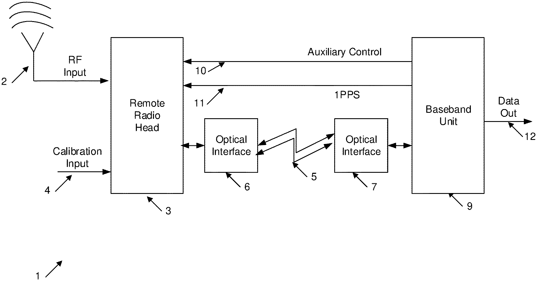
[0011] FIG. 1 is a schematic illustration of the interconnection of Remote Radio Head Units with a Baseband unit;
[0012] FIG. 2 illustrates a Remote Radio Head Unit in more detail;
[0013] FIG. 3 illustrates the Baseband Unit in more detail;
[0014] FIG. 4 illustrates a first architecture for chaining Baseband Units;
[0015] FIG. 5 illustrates a one arrangement of multiple RRH units connected to a single BBU.
DETAILED DESCRIPTION
[0016] The preferred embodiments provide for a system and method which provide for a variation of the split-system topology which is tailored for receive-only applications, such as spectrum monitoring, data acquisition or in-system RF chain diagnosis. The embodiments feature a greatly simplified RRH, as digital down conversion is shifted back to the BBU and up conversion circuitry is eliminated as it is not required. The function of the RRH is therefore limited to digitisation of the raw samples from an analogue to digital converter (ADC), transfer of the raw samples over a fibre-optic link back to the BBU, and unit status information.
[0017] Turning initially to FIG. 1, there is illustrates an example arrangement 1. An input antenna signal 2 is input to an RRH unit 3 in addition to calibration input 4. The RRH unit is responsible for signal conversion into a digital form in a synchronised manner under the control of Auxillary control signal 10 and 1PPS timing signal 11 which are output from a BBU 9. The signals can originate from either a BBU or an external facility unit co-located with the RRH. The latter allows for the optical link to be uni-directional. The RRH outputs a signal which is optically converted by optical interface 6 for transmission to BBH optical interface 7. The BBU is responsible for downsampling and transmission 12 of the received data to an external network.
[0018] A fibre-optic link 5, 6, 7 can be built for purpose, using commonly available optical Small Form-factor Pluggable (SFP) modules as a physical layer. An ADC converts the band-limited spectrum into digital samples as defined by the front-end stage of the RRH 3. The optical interface receives the digitised spectrum and, in addition with inputs from a management controller constructs an 8b/10b encoded serial stream, typically between 3 Gbit to 10 Gbit per second (depending on ADC sample clock) then transmits this over a single optical fibre 5. The optical fibre run can be up to 80 km long, however most practical applications use lengths between 1 to 7 km with a sample clock ranging between (but not limited to) 100 to 160 MHz.
[0019] The RRH 3 has two mechanisms for accepting commands from the BBU 12, only one of which is active at any one time. First, is a control packet sent over the fibre-optic interface 6, 7 (by either a second fibre or another wavelength on one fibre); the second is a discrete control interface 10, 11, to the integrated unit manager that interacts with an external piece of hardware, such a facility management unit within the shelter that contains the RRH. In this circumstance, the fibre optic link to the BBU is physically unidirectional.
[0020] When collecting samples continuously, a timestamping mechanism is required in order to ascertain at what time a particular sample was created. The embodiments provide the provision of a synchronisation signal at either the RRH 3 (within the shelter), or directly at the BBU 10, 11. This increases the practical configurations of the system.
[0021] Turning now to FIG. 2, there is illustrated the RRH 3 in more detail. In the example arrangement, the antenna input signal is fed through a coupler 31 for initial attenuation. The coupler allows for a local gain/phase calibration signal to be injected into the same path as the antenna element for on-line diagnosis. It is then subjected to a number of filtering, attenuation and amplification effects to extract a band pass of interest, before being subjected to A/D conversion 39 to a digital form. The sample rate of the A/D converter can be driven by a sample clock 40 whose speed is controlled by an external control signal via control input 42. The ADC can be at a fixed sample rate determined by the external sample clock. The control plane 42 only parses external commands to change the state of the RF path or optical stream parameters. The digital signal is forwarded to Electrical to optical interface 6 for dispatch over optical fiber.
[0022] Turning now to FIG. 3, there is shown the baseband unit (BBU) in more detail. The BBU includes the optical to electrical interface 7 for initial conversion of the optical signal to a corresponding digital electrical form. Subsequently, the digital signals are subjected to a series of digital down conversion 45-47 under control of BBU control unit 52, before being output to DDR memory 50. Subsequently, the received information can be transmitted externally via Ethernet interface 51.
[0023] The following capabilities are introduced by the embodiments:
[0024] Expansion
[0025] Each BBU contains a set of software programmable digital down converters (DDC) e.g. 45-47 for converting slices of the digitised spectrum into baseband I/Q samples for further signal processing. There may be circumstances where a single BBU may not have sufficient DDCs to perform a particular task off of a single RRH stream. Rather than replacing the BBU with a model with more DDCs, there is provided a daisy-chaining mechanism that leverages the unidirectional mode of the RRH fibre optic stream. By utilising the unused optical transmitter in each BBU, the stream from a single RRH can be repeated to multiple BBUs using fibre-optic patch leads allowing those BBUs to contribute their DDCs to the signal processing chain on the same stream.
[0026] FIG. 4 illustrates one such arrangement 60, wherein a first front end card 61 is able to drive a series of back end cards 62-64 which are able to apply further digital down sampling and processing of the digital stream.
[0027] Data Isolation
[0028] The BBUs can be connected to a wider network which contains Signal Processing Computers. Often this connection is achieved through industry standard protocols (I.E. Ethernet) and may have administrative restrictions imposed on nodes which require connection to a given network. Some applications even consider the DDC parameters as sensitive information, and wish to limit the distribution of those parameters as much as possible. Splitting the receiver in the traditional sense would extend the network boundary to the RRH, which may be physically located in areas contrary to the network security policy and may introduce potentially burdensome administrative overheads to installations where the embodiments are deployed.
[0029] By virtue of the unidirectional optical link and built-for-purpose design, the installation of this embodiment restricts to the network boundary to the BBU allowing the RRH and its associated shelter to be installed without impacting local network security policy. The facility unit required to control the RRH can be on a completely separate network or operate on an autonomous schedule basis. In a similar vein, proving that the link is purely unidirectional and that the RRH has no knowledge of DDC parameters provides greater security confidence than having a bi-directional link claims to not radiate back up out the connected antenna.
[0030] Installation Diversity
[0031] This embodiment allows digital split receivers to be installed in physically diverse configurations. One such arrangement is as illustrated in FIG. 5. In this arrangement, a main BBU unit 71 housed in a main building is used to drive a series of RRH units 72-75 which are housed remotely and interconnected by optical cables e.g. 78. The RRH units are, in turn, each used to drive a series of antenna devices e.g. 79, which are interconnected to the RRH units by coaxial cables 80. Each RRH can drive multiple antenna devices and receive mains power input 82.
[0032] The low computational requirements of individual RRHs dramatically reduce power requirements as compared with a monolithic receiver or traditional RRH. This in turn reduces the facilities requirements for power reticulation and cooling leading to cost savings or opportunities to use facilities that otherwise would have been discounted.
[0033] The unidirectional fibre optic link to the BBU dramatically reduces the amount of coaxial cable required to be run to the antenna element, hence significantly reducing installation costs. Additionally the diameter of fibre optic strands are on average less than 1/10th of quality low-loss coax. By virtue of data isolation, the network boundary is not extended when used in unidirectional mode which allows connectivity to networks with a security policy. Optical isolation allows the RRHs to be installed in environmentally hazardous environments without putting additional risk on the comparatively expensive BBU and signal processing computers on the connected network.
[0034] Interpretation
[0035] Reference throughout this specification to "one embodiment", "some embodiments" or "an embodiment" means that a particular feature, structure or characteristic described in connection with the embodiment is included in at least one embodiment of the present invention. Thus, appearances of the phrases "in one embodiment", "in some embodiments" or "in an embodiment" in various places throughout this specification are not necessarily all referring to the same embodiment, but may. Furthermore, the particular features, structures or characteristics may be combined in any suitable manner, as would be apparent to one of ordinary skill in the art from this disclosure, in one or more embodiments.
[0036] As used herein, unless otherwise specified the use of the ordinal adjectives "first", "second", "third", etc., to describe a common object, merely indicate that different instances of like objects are being referred to, and are not intended to imply that the objects so described must be in a given sequence, either temporally, spatially, in ranking, or in any other manner.
[0037] In the claims below and the description herein, any one of the terms comprising, comprised of or which comprises is an open term that means including at least the elements/features that follow, but not excluding others. Thus, the term comprising, when used in the claims, should not be interpreted as being limitative to the means or elements or steps listed thereafter. For example, the scope of the expression a device comprising A and B should not be limited to devices consisting only of elements A and B. Any one of the terms including or which includes or that includes as used herein is also an open term that also means including at least the elements/features that follow the term, but not excluding others. Thus, including is synonymous with and means comprising.
[0038] As used herein, the term "exemplary" is used in the sense of providing examples, as opposed to indicating quality. That is, an "exemplary embodiment" is an embodiment provided as an example, as opposed to necessarily being an embodiment of exemplary quality.
[0039] It should be appreciated that in the above description of exemplary embodiments of the invention, various features of the invention are sometimes grouped together in a single embodiment, FIG., or description thereof for the purpose of streamlining the disclosure and aiding in the understanding of one or more of the various inventive aspects. This method of disclosure, however, is not to be interpreted as reflecting an intention that the claimed invention requires more features than are expressly recited in each claim. Rather, as the following claims reflect, inventive aspects lie in less than all features of a single foregoing disclosed embodiment. Thus, the claims following the Detailed Description are hereby expressly incorporated into this Detailed Description, with each claim standing on its own as a separate embodiment of this invention.
[0040] Furthermore, while some embodiments described herein include some but not other features included in other embodiments, combinations of features of different embodiments are meant to be within the scope of the invention, and form different embodiments, as would be understood by those skilled in the art. For example, in the following claims, any of the claimed embodiments can be used in any combination.
[0041] Furthermore, some of the embodiments are described herein as a method or combination of elements of a method that can be implemented by a processor of a computer system or by other means of carrying out the function. Thus, a processor with the necessary instructions for carrying out such a method or element of a method forms a means for carrying out the method or element of a method. Furthermore, an element described herein of an apparatus embodiment is an example of a means for carrying out the function performed by the element for the purpose of carrying out the invention.
[0042] In the description provided herein, numerous specific details are set forth. However, it is understood that embodiments of the invention may be practiced without these specific details. In other instances, well-known methods, structures and techniques have not been shown in detail in order not to obscure an understanding of this description.
[0043] Similarly, it is to be noticed that the term coupled, when used in the claims, should not be interpreted as being limited to direct connections only. The terms "coupled" and "connected," along with their derivatives, may be used. It should be understood that these terms are not intended as synonyms for each other. Thus, the scope of the expression a device A coupled to a device B should not be limited to devices or systems wherein an output of device A is directly connected to an input of device B. It means that there exists a path between an output of A and an input of B which may be a path including other devices or means. "Coupled" may mean that two or more elements are either in direct physical or electrical contact, or that two or more elements are not in direct contact with each other but yet still co-operate or interact with each other.
[0044] Thus, while there has been described what are believed to be the preferred embodiments of the invention, those skilled in the art will recognize that other and further modifications may be made thereto without departing from the spirit of the invention, and it is intended to claim all such changes and modifications as falling within the scope of the invention. For example, any formulas given above are merely representative of procedures that may be used. Functionality may be added or deleted from the block diagrams and operations may be interchanged among functional blocks. Steps may be added or deleted to methods described within the scope of the present invention.
* * * * *
D00000
D00001
D00002
D00003
D00004
D00005
XML
uspto.report is an independent third-party trademark research tool that is not affiliated, endorsed, or sponsored by the United States Patent and Trademark Office (USPTO) or any other governmental organization. The information provided by uspto.report is based on publicly available data at the time of writing and is intended for informational purposes only.
While we strive to provide accurate and up-to-date information, we do not guarantee the accuracy, completeness, reliability, or suitability of the information displayed on this site. The use of this site is at your own risk. Any reliance you place on such information is therefore strictly at your own risk.
All official trademark data, including owner information, should be verified by visiting the official USPTO website at www.uspto.gov. This site is not intended to replace professional legal advice and should not be used as a substitute for consulting with a legal professional who is knowledgeable about trademark law.