Solid Electrolyte Body, All-solid-state Battery, Method For Producing Solid Electrolyte Body, And Method For Producing All-solid-state Battery
YANAGAWA (deceased); Masaki ; et al.
U.S. patent application number 16/964438 was filed with the patent office on 2021-02-18 for solid electrolyte body, all-solid-state battery, method for producing solid electrolyte body, and method for producing all-solid-state battery. The applicant listed for this patent is JAPAN FINE CERAMICS CO., LTD.. Invention is credited to Akira HATAKEYAMA, Hitoshi TAKAMURA, Masaki YANAGAWA (deceased).
| Application Number | 20210050622 16/964438 |
| Document ID | / |
| Family ID | 1000005236443 |
| Filed Date | 2021-02-18 |


| United States Patent Application | 20210050622 |
| Kind Code | A1 |
| YANAGAWA (deceased); Masaki ; et al. | February 18, 2021 |
SOLID ELECTROLYTE BODY, ALL-SOLID-STATE BATTERY, METHOD FOR PRODUCING SOLID ELECTROLYTE BODY, AND METHOD FOR PRODUCING ALL-SOLID-STATE BATTERY
Abstract
Provided is a method for easily producing a thin-membrane solid electrolyte body. A molded body (11) of a first ceramic is prepared, and the molded body (11) is fired in a first temperature range to prepare a porous body (110). A thin membrane-shaped molded body (12) composed of a second ceramic containing a solid electrolyte is prepared on at least a part of a surface of the porous body (110). A dense body (120) is prepared by firing the thin membrane-shaped molded body (12). As a result, a solid electrolyte body (1) including the porous body (110) as a support and the dense body (120) of a thin membrane-shaped electrolyte integrally formed with at least a part of the surface of the porous body (110), is produced.
| Inventors: | YANAGAWA (deceased); Masaki; (MIYAGI, JP) ; HATAKEYAMA; Akira; (MIYAGI, JP) ; TAKAMURA; Hitoshi; (MIYAGI, JP) | ||||||||||
| Applicant: |
|
||||||||||
|---|---|---|---|---|---|---|---|---|---|---|---|
| Family ID: | 1000005236443 | ||||||||||
| Appl. No.: | 16/964438 | ||||||||||
| Filed: | February 7, 2019 | ||||||||||
| PCT Filed: | February 7, 2019 | ||||||||||
| PCT NO: | PCT/JP2019/004495 | ||||||||||
| 371 Date: | July 23, 2020 |
| Current U.S. Class: | 1/1 |
| Current CPC Class: | H01M 10/0562 20130101; H01M 4/80 20130101; H01M 2300/0074 20130101 |
| International Class: | H01M 10/0562 20060101 H01M010/0562; H01M 4/80 20060101 H01M004/80 |
Foreign Application Data
| Date | Code | Application Number |
|---|---|---|
| Feb 8, 2018 | JP | 2018-021439 |
Claims
1. A method for producing a solid electrolyte body comprising: a porous body composed of a first ceramic; and a thin membrane-shaped dense body composed of a second ceramic containing a solid electrolyte and integrally formed with at least a part of a surface of the porous body, wherein the method comprises: a step of preparing the porous body by preparing a first molded body and firing the first molded body; and a step of preparing a thin membrane-shaped second molded body of the ceramics on at least a part of the surface of the porous body, and preparing the dense body by firing the second molded body.
2. A method for producing an all-solid state battery, the method comprising: a step of producing a solid electrolyte body by the method for producing a solid electrolyte body according to claim 1; and a step of filling open pores of the porous body forming the solid electrolyte body with an active material.
3. A solid electrolyte body comprising: a porous body composed of a first ceramic of a non-lithium ion electrolyte; and a thin membrane-shaped dense body composed of a second ceramic containing a solid electrolyte and integrally formed with at least a part of a surface of the porous body.
4. An all-solid state battery comprising: a first electrode formed from a porous body composed of a first ceramic of a non-lithium ion electrolyte and an active material filling open pores of the porous body; an electrolyte membrane formed from a thin membrane-shaped dense body composed of a second ceramic containing a solid electrolyte and integrally formed with at least a part of a surface of the porous body; and a second electrode which includes an active material and which is provided on a surface opposite to the first electrode with the electrolyte membrane interposed therebetween.
5. The all-solid state battery according to claim 4, wherein the second electrode is formed from a porous body composed of the first ceramic and an active material filling open pores of the porous body.
Description
TECHNICAL FIELD
[0001] The present invention relates to a method for producing a solid electrolyte body and a method for producing an all-solid state battery in which the solid electrolyte body is used.
BACKGROUND ART
[0002] A method for producing a solid electrolyte body for an all-solid state battery has been proposed (see Patent Literature 1). Specifically, a first molded body is obtained by molding a first ceramic material containing a solid electrolyte (for example, Li.sub.3PO.sub.4, LiPON, Li.sub.2S--SiS.sub.2, Li.sub.2S--P.sub.2S.sub.5, Li.sub.2S--B.sub.2S.sub.3 etc.) into a plate shape, and a dense body is formed by firing the first molded body. A second molded body is obtained by applying a second ceramic material containing a solid electrolyte that is the same as or different from the solid electrolyte forming the dense body to one surface of the dense body, and the second molded body is additionally fired together with the dense body at a temperature lower than the firing temperature of the first molded body to form on at least one surface of the dense body a porous layer integrated by firing.
CITATION LIST
Patent Literature
[0003] Patent Literature 1: Japanese Patent No. 5281896
SUMMARY OF INVENTION
Technical Problem
[0004] According to the prior art described above, a first molded body is obtained by a pressing method, a doctor blade method, a reverse roll coater method, or the like, and a solid electrolyte having a dense body with a thickness of 5 .mu.m to 100 .mu.m is obtained. However, in actual practice, although it is not impossible to prepare an individual solid electrolyte having a thin dense body with a thickness of, for example, 100 .mu.m or less, such a solid electrolyte is very difficult to produce because of cracking that can arise as a result of the insufficient strength of the solid electrolyte due to its own thinness.
[0005] Therefore, it is an object of the present invention to provide a method for producing a solid electrolyte body while facilitating the preparation of a solid electrolyte having a thin dense body, a method for producing an all-solid state battery, and the like.
Solution to Problem
[0006] The present invention relates to a method for producing a solid electrolyte body comprising a porous body composed of a first ceramic, and a dense body containing a thin membrane-shaped solid electrolyte composed of a second ceramic containing a solid electrolyte and integrally formed with at least a part of a surface of the porous body.
[0007] The method for producing the solid electrolyte body of the present invention comprises a step of preparing the porous body by preparing a first molded body and firing the first molded body, and a step of preparing a thin membrane-shaped second molded body of the ceramics on at least a part of the surface of the porous body, and preparing the dense body containing the solid electrolyte by firing the second molded body.
[0008] A method for producing an all-solid state battery according to the present invention is characterized by comprising a step of producing the solid electrolyte body by the method for producing a solid electrolyte body according to the present invention, and a step of filling open pores of the porous body forming the solid electrolyte body with an active material, which is an electrode.
Advantageous Effect of Invention
[0009] According to the method for producing a solid electrolyte body and the method for producing an all-solid state battery of the present invention, a thin membrane-shaped second molded body is formed on at least a part of the surface of a porous body prepared in advance, and a dense body containing a thin membrane-shaped solid electrolyte is prepared by firing the second molded body. Therefore, it is possible to produce a solid electrolyte body and an all-solid state battery while facilitating the production of a thin dense body.
BRIEF DESCRIPTION OF DRAWINGS
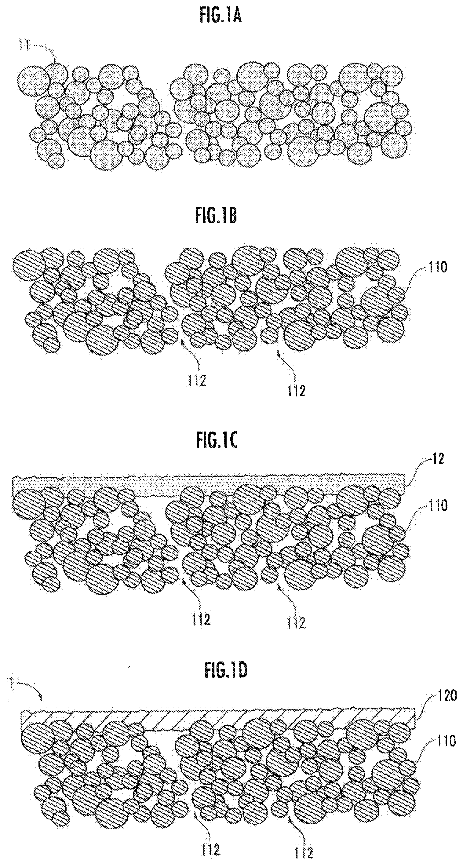
[0010] FIG. 1A is an explanatory diagram relating to a step of preparing a first molded body.
[0011] FIG. 1B is an explanatory diagram relating to a step of preparing a porous body.
[0012] FIG. 1C is an explanatory diagram relating to a step of preparing a second molded body.
[0013] FIG. 1D is an explanatory diagram relating to a step of preparing a dense body.
[0014] FIG. 2A is an explanatory diagram relating to a step of preparing a first electrode.
[0015] FIG. 2B is an explanatory diagram relating to a step of preparing a second electrode.
[0016] FIG. 2C is an explanatory diagram relating to a step of joining electrodes and current collectors.
[0017] FIG. 3A is an explanatory diagram relating to a structure of a solid electrolyte body according to another embodiment.
[0018] FIG. 3B is an explanatory diagram relating to a structure of an all-solid state battery according to another embodiment.
DESCRIPTION OF EMBODIMENTS
[0019] (Structure of Solid Electrolyte Body)
[0020] As shown in FIG. 1D, a solid electrolyte body 1 produced by a method as one embodiment of the present invention comprises a flat plate-like porous body 110 and a dense body 120 containing a thin membrane-shaped solid electrolyte that is closely adhered to one main surface of the porous body 110.
[0021] The porous body 110 is composed of a first ceramic of a non-lithium ion electrolyte, and has a plurality of open pores 112 that form passaging communicating from one main surface to the other main surface. The thickness of the porous body 110 is, for example, in the range of 100 .mu.m to 1 mm or in the range of 100 .mu.m to 500 .mu.m. The porosity of the porous body 110 is, for example, in the range of 10 to 70 vol. % or in the range of 20 to 50 vol. %. The porosity is measured by a mercury porosimetry method.
[0022] For example, partially stabilized zirconia is used as the first ceramic of the non-lithium ion electrolyte.
[0023] The first ceramic may contain a lithium ion solid electrolyte. The solid electrolyte is, for example, a solid electrolyte including lithium as a mobile ion, such as a lithium ion conductive glass-like solid electrolyte of Li.sub.3PO.sub.4, LiPON in which nitrogen is mixed in Li.sub.3PO.sub.4, Li.sub.2S--SiS.sub.2, Li.sub.2S--P.sub.2S.sub.5, Li.sub.2S--B.sub.2S.sub.3 and the like, or a lithium ion conductive glass-like solid electrolyte in which a lithium halide such as LiI or a lithium oxyacid salt such as Li.sub.3PO.sub.4 is doped in those glasses. For example, a titanium oxide type solid electrolyte including lithium, titanium, and oxygen, such as Li.sub.xLa.sub.yTiO.sub.3 (0<x<1, 0<y<1 (for example, x=0.35, y=0.55)), phosphoric acid compounds, Li.sub.1+xAl.sub.xTi.sub.2-x(PO.sub.4).sub.3, exhibits stable performance even when fired in an oxygen atmosphere.
[0024] The dense body 120 is formed from a second ceramic containing the above-described solid electrolyte. There is no limitation on the thickness of the dense body 120, but the thickness is, for example, in the range of 0.5 .mu.m to 100 .mu.m. The solid electrolyte contained in the first ceramic and the solid electrolyte contained in the second ceramic may be the same or different.
[0025] (Method for Producing Solid Electrolyte Body)
[0026] A method for producing the solid electrolyte body as one embodiment of the present invention includes (S1) a step of preparing a first molded body, (S2) a step of preparing a porous body, (S3) a step of preparing a second molded body, and (S4) a step of preparing a dense body.
[0027] In step (S1), a first molded body 11 is prepared from a material including the first ceramic (see FIG. 1A). As the method for preparing the first molded body 11, for example, a sheet molding method or a roll compaction method is employed. For example, a binder such as butyral resin is mixed to prepare a paste, and the first molded body 11 is prepared by the method described above.
[0028] A pore-forming agent such as starch or carbon may be added to the first ceramics in order to adjust the porosity and the pore size of the porous body 110. When the first molded body 11 is fired, the pore-forming agent disappears and the open pores 112 are formed. The thickness of the porous body 110 obtained by firing is, for example, in the range of 100 .mu.m to 1 mm or in the range of 100 .mu.m to 500 .mu.m.
[0029] In step (S2), the porous body 110 is prepared by firing the first molded body 11 in a first temperature range (see FIG. 1B). A plurality of open pores 112 that three-dimensionally communicate from one main surface of the porous body 110 to the other main surface are formed from the traces of the binder, the pore-forming agent included in the raw material being removed by decomposition, and the like. The first temperature range is set according to the type of the first ceramic, the binder, the pore forming agent, and the like, but is, for example, in the range of 800 to 1500.degree. C. or in the range of 1000 to 1300.degree. C. As will be described later, in step (S4), the porous body 110 is exposed to the temperature environment included in the second temperature range, and therefore it is preferable to control the firing time to be, for example, in the range of 1 to 5 hours, and, for example, in the range of 2 to 3 hours, in order to avoid an excessive reduction in porosity due to over-firing of the porous body 110.
[0030] In step (S3), a thin membrane-shaped second molded body 12 composed of a material including a second ceramic is prepared on one main surface of the porous body 110 (see FIG. 1C). As the method for preparing the second molded body 12, for example, a coating method such as a slurry printing method, a CVD method, a sputtering method, or an aerosol deposition method is employed. The thickness of the second molded body 12 is not limited, but is in the range of, for example, 0.5 .mu.m to 100 .mu.m, or in the range of 5 .mu.m to 30 .mu.m.
[0031] In step (S4), the dense body 120 is prepared on one main surface of the porous body 110 by firing the second molded body 12 in a second temperature range (see FIG. 1D). The second temperature range is, for example, in the range of 900 to 1500.degree. C. or in the range of 1000 to 1300.degree. C. When the first ceramic and the second ceramic are the same, necking of the first ceramic and the second ceramic tends to occur at the connection interface between the porous body 110 and the dense body 120, so that the joining strength between the porous body 110 and the dense body 120 is improved. To avoid an excessive reduction in the porosity due to overfiring of the porous body 110, the firing time is preferably controlled to be in the range of, for example, 1 to 5 hours, and for example, in the range of 2 to 3 hours.
[0032] As shown in FIG. 1D, after carrying out steps (S1) to (S4), a solid electrolyte body 1 is produced having the porous body 110 and the dense body 120, which is integrally formed with the porous body 110 on one main surface of the porous body 110.
[0033] (Structure of all-Solid State Battery)
[0034] As an embodiment of the present invention, an all-solid state battery 2 produced by the present method comprises, as shown in FIG. 2C, the solid electrolyte body 1 shown in FIG. 1D, a first electrode 21, a second electrode 22, a first electrode current collector 41 electrically connected to the first electrode 21, and a second electrode current collector 42 electrically connected to the second electrode 22.
[0035] The first electrode 21 is formed from the active material filling the open pores 112 of the porous body 110 forming the solid electrolyte body 1. When the first electrode 21 is a positive electrode, examples of active materials (positive electrode active materials) that may be employed include manganese dioxide (MnO.sub.2), iron oxide, copper oxide, nickel oxide, lithium-manganese composite oxides (for example, Li.sub.xMn.sub.2O.sub.4 or Li.sub.xMnO.sub.2) (for example, 1<x<5 (the same applies below)), lithium-nickel composite oxides (for example, Li.sub.xNiO.sub.2), lithium-cobalt composite oxides (for example, Li.sub.xCoO.sub.2), lithium-nickel cobalt composite oxides (for example, LiNi.sub.1-yCo.sub.yO.sub.2) (for example, 0<y<1 (the same applies below)), lithium-manganese cobalt composite oxides (for example, LiMn.sub.yCo.sub.1-yO.sub.2), spinel type lithium-manganese nickel composite oxides (for example, Li.sub.xMn.sub.2-yNi.sub.yO.sub.4), lithium-phosphate compounds having an olivine structure (for example, Li.sub.xFePO.sub.4, Li.sub.xFe.sub.1-yMn.sub.yPO.sub.4, Li.sub.xCoPO.sub.4, lithium-phosphate compounds having a NASICON structure (for example, Li.sub.xV.sub.2(PO.sub.4).sub.3), iron sulfate (Fe.sub.2(SO.sub.4).sub.3), vanadium oxides (for example, V.sub.2O.sub.5), and the like. An electron conduction aid such as acetylene black, carbon black, graphite, various carbon fibers, or carbon nanotubes may be added to the positive electrode active material.
[0036] When the first electrode 21 is a negative electrode, examples of active materials (negative electrode active materials) that may be employed include carbon, metal lithium (Li), metal compounds, metal oxides, Li metal compounds, Li metal oxides (including lithium-transition metal composite oxides), boron-added carbon, graphite, compounds having a NASICON structure, and the like.
[0037] Examples of the carbon that may be employed include conventionally known carbon materials, such as graphite carbon, hard carbon, and soft carbon. Examples of the metal compound that may be employed include LiAl, LiZn, Li.sub.3Bi, Li.sub.3Cd, Li.sub.3Sd, Li.sub.4Si, Li.sub.44Pb, Li.sub.44Sn, Li.sub.0.17C (LiC.sub.6), and the like. Examples of the metal oxide that may be employed include SnO, SnO.sub.2, GeO, GeO.sub.2, In.sub.2O, In.sub.2O.sub.3, PbO, PbO.sub.2, Pb.sub.2O.sub.3, Pb.sub.3O.sub.4, Ag.sub.2O, AgO, Ag.sub.2O.sub.3, Sb.sub.2O.sub.3, Sb.sub.2O.sub.4, Sb.sub.2O.sub.5, SiO, ZnO, CoO, NiO, TiO.sub.2, FeO, and the like. Examples of the Li metal compound may include Li.sub.3FeN.sub.2, Lo.sub.2.6Co.sub.0.4N, Li.sub.2.6Cu.sub.0.4N, and the like. Examples of the Li metal oxide (lithium-transition metal composite oxide) may include a lithium-titanium composite oxide represented by Li.sub.4Ti.sub.5O.sub.12. Examples of the boron-added carbon may include boron-added carbon and boron-added graphite. The conductive auxiliary materials described above in relation to the positive electrode active material may be added to the negative electrode active material.
[0038] The second electrode 22 is formed by molding an electrode material including the active material into a thin membrane shape or a sheet shape having a predetermined thickness.
[0039] Examples of the material forming the first electrode current collector 41 and the second electrode current collector 42 include general electron-conductive metal materials such as platinum (Pt), platinum (Pt)/palladium (Pd), gold (Au), silver (Ag), aluminum (Al), copper (Cu), ITO (indium-tin oxide film), and SUS plate.
[0040] (Method for Producing all-Solid State Battery)
[0041] The method for producing an all-solid state battery as one embodiment of the present invention includes, in addition to steps (S1) to (S4) of the method for producing a solid electrolyte body as one embodiment of the present invention, a step (S5) of filling the open pores 112 of the porous body 110 with an active material, a step (S6) of firing the active material to form the first electrode 21, a step (S7) of forming the second electrode 22, a step (S8) of connecting the first electrode current collector 41 to the first electrode 21, and a step (S9) of connecting the second electrode current collector 42 to the second electrode 22. The description of steps (S1) to (S4) will be omitted here.
[0042] In step (S5), the open pores 112 of the porous body 110 forming the solid electrolyte body 1 are filled with the active material. Examples of active materials that may be used include an active material such as positive electrode active material or a negative electrode active material that has been atomized and formed into a colloidal dispersion solution by using an organic solvent, an aqueous solvent, pure water, or the like, a solution in which the active material has been formed as a sol, and the like. The filling of the open pores 112 of the porous body 110 with the active material is performed by, for example, dropping or dipping a sol-like active material on the surface of the porous body 110 in air, an Ar atmosphere, or a vacuum. If the open pores 112 of the porous body 110 are not sufficiently filled with the active material, the filling operation is repeated a plurality of times.
[0043] In step (S6), the active material is fired as necessary to form the first electrode 21 (see FIG. 2A). The firing temperature when firing the active material is controlled so as to be in the range of, for example, 700 to 1100.degree. C. However, when an electron conduction aid such as carbon is added, firing is not preferable, and step (S6) is omitted.
[0044] In step (S7), the second electrode 22 is formed by, for example, a coating method such as a slurry printing method or a roll coater method, and then, similar to as described above, fired as necessary to prepare the second electrode 22. The second electrode 22 may be formed by a sputtering method, a resistance heating deposition method, an ion beam deposition method, an electron beam deposition method, and the like.
[0045] In step (S8), the first electrode current collector 41 is formed in a state of being connected to the first electrode 21 by a method such as a sputtering method, an ion beam deposition method, or an electron beam deposition method (see FIG. 2C). In step (S9), the second electrode current collector 42 is formed in a state of being connected to the second electrode 22 by a method such as a sputtering method, an ion beam deposition method, or an electron beam deposition method (see FIG. 2C). Note that steps (S8) and (S9) may be omitted.
[0046] After steps (S1) to (S9) or steps (S1) to (S5) and (S7) to (S9), as shown in FIG. 2C, the porous body 110 and an all-solid state battery 2 including the dense body 120 integrally formed with the porous body 110 on one of the main surfaces of the porous body 110, the first electrode 21 having at least a part thereof formed from an active material filling the open pores 112 of the porous body 110, the second electrode 22 formed on the other main surface of the dense body 120, the first electrode current collector 41 electrically connected to the first electrode 21, and the second electrode current collector 42 electrically connected to the second electrode 22, is produced.
Effects
[0047] According to the method of the present invention, the thin membrane-shaped second molded body 12 is formed on at least a part of the surface of the porous body 110 prepared in advance, and the thin membrane-shaped dense body 120 is prepared by firing the second molded body 12 (see FIGS. 1C and 1D). Therefore, the solid electrolyte body 1 and the all-solid state battery 2 can be produced while facilitating the preparation of the thin dense body 120.
Other Embodiments of the Present Invention
[0048] As shown in FIG. 3A, the solid electrolyte body 1 may be produced having a pair of the porous bodies 110 and the dense body 120 sandwiched by the pair of porous bodies 110. For example, after preparing a pair of porous bodies 110, the second molded body 12 is prepared on one main surface of one of the porous bodies 110 (see FIG. 1C). After that, one main surface of the other porous body 110 is brought into contact with the second molded body 12 to produce the second molded body 12 sandwiched by the pair of porous bodies 110, which is then fired to produce the solid electrolyte shown in FIG. 3A.
[0049] Using the solid electrolyte body 1 shown in FIG. 3A, the all-solid state battery 2 shown in FIG. 3B may also be produced by performing steps (S5), (S6), (S8), and (S9) or steps (S5), (S8), and (S9). In this case as well, steps (S8) and (S9) may be omitted.
REFERENCE SIGNS LIST
[0050] 1 solid electrolyte body [0051] 2 all-solid state battery [0052] 11 first molded body [0053] 12 second molded body [0054] 21 first electrode [0055] 22 second electrode [0056] 41 first electrode current collector [0057] 42 second electrode current collector [0058] 110 porous body [0059] 112 open pore [0060] 120 dense body.
* * * * *
D00000
D00001
D00002
D00003
XML
uspto.report is an independent third-party trademark research tool that is not affiliated, endorsed, or sponsored by the United States Patent and Trademark Office (USPTO) or any other governmental organization. The information provided by uspto.report is based on publicly available data at the time of writing and is intended for informational purposes only.
While we strive to provide accurate and up-to-date information, we do not guarantee the accuracy, completeness, reliability, or suitability of the information displayed on this site. The use of this site is at your own risk. Any reliance you place on such information is therefore strictly at your own risk.
All official trademark data, including owner information, should be verified by visiting the official USPTO website at www.uspto.gov. This site is not intended to replace professional legal advice and should not be used as a substitute for consulting with a legal professional who is knowledgeable about trademark law.