Modular Flare System Skid
Ciprick; Kelly P. ; et al.
U.S. patent application number 16/542550 was filed with the patent office on 2021-02-18 for modular flare system skid. The applicant listed for this patent is REVO TESTING TECHNOLOGIES, LLC. Invention is credited to Kelly P. Ciprick, Tyson Smith.
| Application Number | 20210048195 16/542550 |
| Document ID | / |
| Family ID | 1000004289464 |
| Filed Date | 2021-02-18 |


| United States Patent Application | 20210048195 |
| Kind Code | A1 |
| Ciprick; Kelly P. ; et al. | February 18, 2021 |
MODULAR FLARE SYSTEM SKID
Abstract
A modular flare system skid having a base, a flare stack, and one or more removable modules. The flare can be of any size required and can come in sections if needed. The removable modules can have lift points for easy manipulation and transport, as well as housing ancillary equipment for use with the flare stack.
| Inventors: | Ciprick; Kelly P.; (Houston, TX) ; Smith; Tyson; (Fruita, CO) | ||||||||||
| Applicant: |
|
||||||||||
|---|---|---|---|---|---|---|---|---|---|---|---|
| Family ID: | 1000004289464 | ||||||||||
| Appl. No.: | 16/542550 | ||||||||||
| Filed: | August 16, 2019 |
| Current U.S. Class: | 1/1 |
| Current CPC Class: | F23G 2203/70 20130101; F23G 2203/60 20130101; F23G 7/085 20130101 |
| International Class: | F23G 7/08 20060101 F23G007/08 |
Claims
1. A modular flare system skid comprising: a. a base; b. a flare stack; and c. a removable module.
2. The skid of claim 1, wherein the base further comprises one or more outriggers.
3. The skid of claim 1, wherein the flare stack is in a plurality of sections.
4. The skid of claim 1, wherein the removable module comprises lift points.
5. The skid of claim 1, wherein ancillary equipment stored on the removable module comprises: a. a seal drum; b. a knockout drum; c. a gas recovery system; d. a steam injection system; e. a pilot flame; f. an ignition; g. a pipe; h. a pipe fitting; i. an instrument; or j. combinations thereof.
Description
FIELD
[0001] The present disclosure generally relates to a modular flare system skid.
BACKGROUND
[0002] Gas flaring is a common method of combusting unwanted or excess gases and/or liquids either as a means of disposal, or as a safety measure, such as to relieve pressure.
[0003] Fluid products can be released during normal or unplanned operation in many industrial processes, such as oil-gas extraction, refineries, chemical plants, the coal industry, or landfills.
[0004] Often in industry, flares will be temporarily placed at specific locations, or added to increase flaring capacity. One method of adding a flare may be to bring a flare in sections or in a folded manner and set up the flare at the desired location.
[0005] Current mobile flare systems require heavy equipment, such as cranes, to unload and set up the flare stack. Further, ancillary equipment required for the flare to operate, as well as tie into an industrial system is often inconveniently located at the site of the flare stack.
[0006] Present mobile flares are inefficiently unloaded and assembled, leading to wasted time for labor and additional operational cost.
[0007] The present disclosure provides a modular flare system skid to address the above deficiencies.
BRIEF DESCRIPTION OF THE DRAWINGS
[0008] The detailed description will be better understood in conjunction with the accompanying drawings as follows:
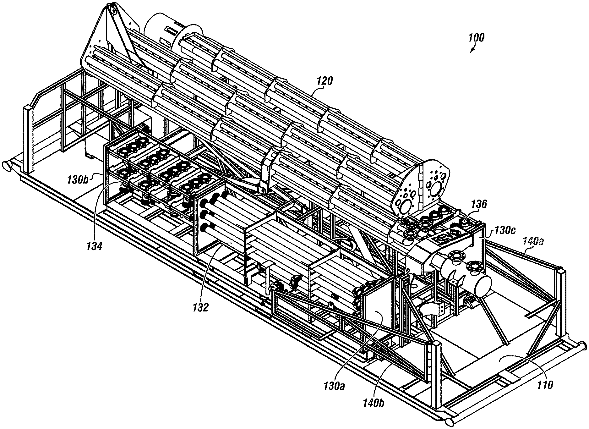
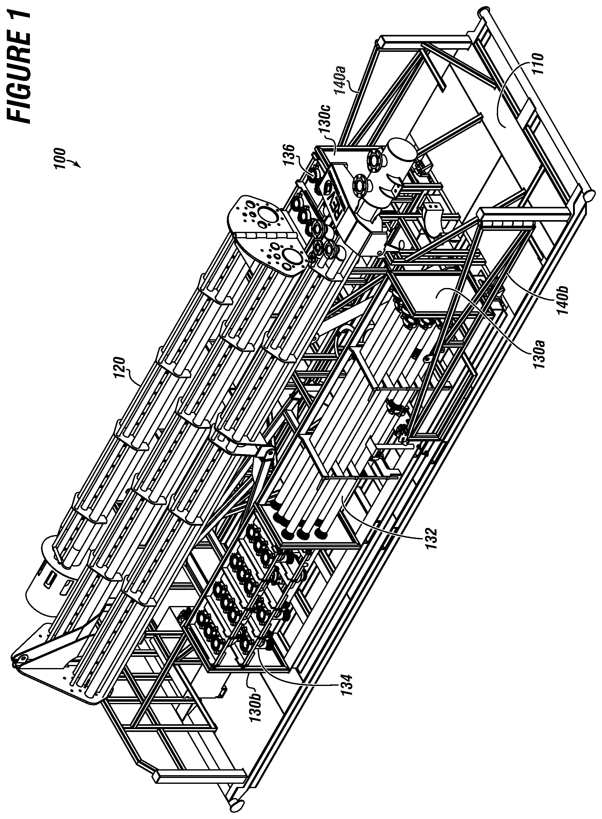
[0009] FIG. 1 shows a perspective view of a modular flare system skid.
[0010] FIG. 2 depicts a top view of a modular flare system skid.
[0011] FIG. 3 depicts an outrigger.
[0012] FIG. 4 depicts a removable module.
[0013] FIG. 5 depicts a flare system with flare stack assembled.
[0014] The embodiments of the present disclosure are detailed below with reference to the listed Figures.
DETAILED DESCRIPTION OF THE EMBODIMENTS
[0015] Before explaining the present disclosure in detail, it is to be understood that the disclosure is not limited to the specifics of embodiments as described and that it can be practiced, constructed, or carried out in various ways.
[0016] While embodiments of the disclosure have been shown and described, modifications thereof can be made by one skilled in the art without departing from the spirit and teachings of the disclosure. The embodiments described herein are exemplary only and are not intended to be limiting.
[0017] Specific structural and functional details disclosed herein are not to be interpreted as limiting, but merely as a basis of the claims and as a representative basis for teaching persons having ordinary skill in the art to variously employ the present embodiments. Many variations and modifications of embodiments disclosed herein are possible and are within the scope of the present disclosure.
[0018] Where numerical ranges or limitations are expressly stated, such express ranges or limitations should be understood to include iterative ranges or limitations of like magnitude falling within the expressly stated ranges or limitations.
[0019] The use of the word "a" or "an" when used in conjunction with the term "comprising" in the claims and/or the specification may mean "one," but it is also consistent with the meaning of "one or more," "at least one," and "one or more than one."
[0020] The word "about", when referring to values, means plus or minus 5% of the stated number.
[0021] The use of the term "optionally" with respect to any element of a claim is intended to mean that the subject element is required, or alternatively, is not required. Both alternatives are intended to be within the scope of the claim. Use of broader terms such as comprises, includes, having, etc. should be understood to provide support for narrower terms such as consisting of, consisting essentially of, comprised substantially of, and the like.
[0022] When methods are disclosed or discussed, the order of the steps is not intended to be limiting, but merely exemplary unless otherwise stated.
[0023] Accordingly, the scope of protection is not limited by the description herein, but is only limited by the claims which follow, encompassing all equivalents of the subject matter of the claims. Each and every claim is hereby incorporated into the specification as an embodiment of the present disclosure. Thus, the claims are a further description and are an addition to the embodiments of the present disclosure.
[0024] The inclusion or discussion of a reference is not an admission that it is prior art to the present disclosure, especially any reference that may have a publication date after the priority date of this application. The disclosures of all patents, patent applications, and publications cited herein are hereby incorporated by reference, to the extent they provide background knowledge; or exemplary, procedural or other details supplementary to those set forth herein.
[0025] The embodiments of the present disclosure generally relate to a modular flare system skid.
[0026] While skid transport systems for flare stacks are known, current state of the art have several deficiencies in design. The present disclosure provides for a simple arrangement that allows for a flare system to be unloaded without the need for heavy equipment while allowing for ancillary equipment to be quickly and efficiently connected.
[0027] A typical flare system can have several components, including but not limited to a seal drum, a knockout drum, a gas recovery system, a steam injection system, a pilot flame with an ignition, a flare stack, and the like. Specialty processes and or environmental regulations can require other equipment as well.
[0028] It is desirable for the modular flare system skid to have one or more of the above components in addition to required piping, pipe fittings, instrumentation, etc. to connect to an existing process.
[0029] The modular flare system of the present disclosure can have a base, a flare stack, and one or more removable modules.
[0030] In embodiments, the base can be configured to slide off a trailer, such as a flatbed trailer to rest on the ground. The base can be equipped with outriggers which are extendable to provide stability to the base.
[0031] A flare stack can be attached to the base. The flare stack can be any size or capacity as used by persons having ordinary skill in the art. In embodiments, the flare stack can be transported or stored on the base in sections to be assembled at a desired location.
[0032] One or more removable modules can be placed on the base to house ancillary equipment. The modules can have one or more lift points to facilitate being lifted, such as by a forklift.
[0033] Ancillary equipment can refer to any equipment utilized in conjunction with the flare stack. The removable modules can be placed in various locations to aid in setting up the flare stack for use.
[0034] Exemplary ancillary equipment includes, but is not limited to a seal drum, a knockout drum, a gas recovery system, a steam injection system, a pilot flame, an ignition, a pipe, a pipe fitting, an instrument, or a sensor.
[0035] Turning now to the Figures, FIG. 1 shows a perspective view of a modular flare system skid.
[0036] A typical mobile or temporary flare stack would require a crane to unload from a truck bed and be placed for operation. The disclosed modular flare system skid 100 can be placed into operation using only a forklift or other similar lifting mechanism without the need for heavy equipment, such as a crane.
[0037] The modular flare system skid 100 can have a base 110. In embodiments, the base 110 can be configured to be rolled off a trailer onto the ground. The modular flare system skid 100 can have a flare stack 120. The stack can be transported in sections to be assembled at the site. The modular flare system skid 100 can have one or more removable modules 130a, 130b, 130c. The removable modules 130a, 130b, 130c can contain various pieces of ancillary equipment 136 for use with the flare stack 120, such as pipe 132 or pipe fittings 134. The modular flare system skid 100 can have one or more outriggers 140a, 140b.
[0038] FIG. 2 depicts a top view of a modular flare system skid.
[0039] Shown here are flare stack 120, removable modules 130a, 130b and outriggers 140a, 140b.
[0040] FIG. 3 depicts an outrigger.
[0041] In embodiments, one or more outrigger 140a can be used for stability when the flare stack is assembled.
[0042] FIG. 4 depicts a removable module.
[0043] Removable module 130 can have lift points 138a, 138b for a forklift, or other similar lifting aid.
[0044] FIG. 5 depicts a flare system with flare stack assembled.
[0045] Shown here is modular flare system skid 100 with flare stack 120 assembled. Outrigger 140b is shown extended for stability of the modular flare system skid 100.
[0046] While the present disclosure emphasizes the presented embodiments and Figures, it should be understood that within the scope of the appended claims, the disclosure might be embodied other than as specifically enabled herein.
* * * * *
D00000
D00001
D00002
D00003
D00004
XML
uspto.report is an independent third-party trademark research tool that is not affiliated, endorsed, or sponsored by the United States Patent and Trademark Office (USPTO) or any other governmental organization. The information provided by uspto.report is based on publicly available data at the time of writing and is intended for informational purposes only.
While we strive to provide accurate and up-to-date information, we do not guarantee the accuracy, completeness, reliability, or suitability of the information displayed on this site. The use of this site is at your own risk. Any reliance you place on such information is therefore strictly at your own risk.
All official trademark data, including owner information, should be verified by visiting the official USPTO website at www.uspto.gov. This site is not intended to replace professional legal advice and should not be used as a substitute for consulting with a legal professional who is knowledgeable about trademark law.