Techniques For Affecting Leaching Profiles In Cutting Elements For Earth-boring Tools And Related Cutting Elements, Earth-boring Tools, And Methods
Cao; Wanjun ; et al.
U.S. patent application number 16/541918 was filed with the patent office on 2021-02-18 for techniques for affecting leaching profiles in cutting elements for earth-boring tools and related cutting elements, earth-boring tools, and methods. The applicant listed for this patent is Baker Hughes Oilfield Operations LLC. Invention is credited to Wanjun Cao, Xu Huang, Steven W. Webb.
| Application Number | 20210047887 16/541918 |
| Document ID | / |
| Family ID | 1000004338022 |
| Filed Date | 2021-02-18 |


| United States Patent Application | 20210047887 |
| Kind Code | A1 |
| Cao; Wanjun ; et al. | February 18, 2021 |
TECHNIQUES FOR AFFECTING LEACHING PROFILES IN CUTTING ELEMENTS FOR EARTH-BORING TOOLS AND RELATED CUTTING ELEMENTS, EARTH-BORING TOOLS, AND METHODS
Abstract
Cutting elements for earth-boring tools may include a cutting table secured to a substrate. The cutting table may include a first region at least substantially free of an infiltrant, a second region comprising the infiltrant, and a passageway extending from an exterior partially through the first region. A distance between the exterior and a boundary between the first region and the second region, as measured from a major surface of the cutting table, may not be constant. Methods of making cutting elements for earth-boring tools may involve placing a sacrificial material among grains of a superabrasive material. The grains of the superabrasive material and the sacrificial material may be exposed to elevated temperature and pressure in a presence of a catalyst material to form a cutting table. The sacrificial material and a portion of the catalyst material may be removed from a first region of the cutting table.
| Inventors: | Cao; Wanjun; (The Woodlands, TX) ; Webb; Steven W.; (The Woodlands, TX) ; Huang; Xu; (Spring, TX) | ||||||||||
| Applicant: |
|
||||||||||
|---|---|---|---|---|---|---|---|---|---|---|---|
| Family ID: | 1000004338022 | ||||||||||
| Appl. No.: | 16/541918 | ||||||||||
| Filed: | August 15, 2019 |
| Current U.S. Class: | 1/1 |
| Current CPC Class: | E21B 10/567 20130101 |
| International Class: | E21B 10/567 20060101 E21B010/567 |
Claims
1. A cutting element for an earth-boring tool, comprising: a cutting table secured to a substrate, the cutting table comprising: a first region at least substantially free of solid infiltrant material in interstitial spaces among interbonded grains of superabrasive material located proximate a cutting face of the cutting table; a second region comprising solid infiltrant material in the interstitial spaces among the interbonded grains of the superabrasive material located proximate the substrate; and a passageway extending from an exterior of the cutting table partially through the first region; and wherein a distance between the exterior of the cutting table and a boundary between the first region and the second region, as measured from a major surface of the cutting table, is not constant.
2. The cutting element for an earth-boring tool of claim 1, wherein the passageway extends from the exterior, partially through the first region, to a location spaced from the substrate by about 5% or more of a thickness of the cutting table, as measured along a longitudinal axis of the cutting element.
3. The cutting element for an earth-boring tool of claim 2, wherein the passageway extends from the exterior, partially through the first region, to a location within the first region spaced from the boundary.
4. The cutting element of claim 1, wherein a shortest distance between walls defining the passageway is greater than a greatest distance between interbonded grains of superabrasive material.
5. The cutting element of claim 4, wherein the shortest distance between walls defining the passageway is between about 0.025 mm and about 1 mm.
6. The cutting element of claim 1, wherein a terminal end of the passageway is located within the cutting table.
7. The cutting element of claim 1, wherein a minimum distance between an opening of the passageway at the exterior of the cutting table and a lateral side surface of the cutting table, as measured in a direction perpendicular to a longitudinal axis of the cutting element, is between about 5% and about 30% of a maximum width of the cutting table, as measured in the same direction.
8. The cutting element of claim 1, wherein the distance between the exterior of the cutting table and the boundary between the first region and the second region varies with radial distance from the longitudinal axis, with angular distance around the longitudinal axis, or both.
9. The cutting element of claim 1, wherein the second region is rotationally symmetrical about the longitudinal axis, reflectively symmetrical about at least one plane intersecting the longitudinal axis, or both.
10. An earth-boring tool, comprising: a cutting element secured to a body, the cutting element comprising: a cutting table secured to a substrate, the cutting table comprising: a first region at least substantially free of solid infiltrant material in interstitial spaces among interbonded grains of superabrasive material located proximate a cutting face of the cutting table; a second region comprising solid infiltrant material in the interstitial spaces among the interbonded grains of the superabrasive material located proximate the substrate; and a passageway extending from an exterior of the cutting table partially through the first region; and wherein a distance between the exterior of the cutting table and a boundary between the first region and the second region, as measured from a major surface of the cutting table, is not constant.
11. A method of making a cutting element for an earth-boring tool, comprising: placing a sacrificial material among grains of a superabrasive material; exposing the grains of the superabrasive material and the sacrificial material to elevated temperature and pressure in a presence of a catalyst material, forming a cutting table including a polycrystalline, superabrasive material; removing the sacrificial material and a portion of the catalyst material from a first region of the cutting table; and leaving a remainder of the catalyst material in a second region of the cutting table.
12. The method of claim 11, wherein placing the sacrificial material among the grains of the superabrasive material comprises placing a metal or metal alloy including 10% by weight or more rhenium among the grains of the superabrasive material.
13. The method of claim 12, wherein placing the metal or metal alloy including 10% by weight or more rhenium among the grains of the superabrasive material comprises placing a tungsten-rhenium alloy or material mixture among the grains of the superabrasive material.
14. The method of claim 11, wherein placing the sacrificial material among the grains of the superabrasive material comprises placing a wire, foil, or sheet of the sacrificial material among the grains of the superabrasive material.
15. The method of claim 14, wherein placing the wire, foil, or sheet of the sacrificial material among the grains of the superabrasive material comprises placing a wire, foil, or sheet including one or more of bends, curves, and straight portions among the grains of the superabrasive material.
16. The method of claim 11, wherein placing the sacrificial material among the grains of the superabrasive material comprises one or more ends of the sacrificial material adjacent to a wall of the mold and otherwise surrounding the sacrificial material in the grains of the superabrasive material.
17. The method of claim 11, further comprising removing the sacrificial material at a greater rate than a rate at which the portion of the catalyst material is removed.
18. The method of claim 17, further comprising removing the sacrificial material at a rate between about 5 times and about 25 times greater than a rate at which the portion of the catalyst material is removed.
19. The method of claim 11, wherein removing the sacrificial material and the portion of the catalyst material comprises exposing the cutting table to a leaching agent.
20. The method of claim 11, wherein the acts of removing the sacrificial material and the portion of the catalyst material from the first region and leaving the remainder of the catalyst material in the second region comprise rendering a distance between an exterior of the cutting table and a boundary between the first region and the second region, as measured from a major surface of the cutting table, non-constant.
Description
FIELD
[0001] This disclosure relates generally to cutting elements for earth-boring tools and related earth-boring tools and methods. More specifically, disclosed embodiments relate to techniques for producing a desired leach profile within a cutting table of a cutting element of an earth-boring tool.
BACKGROUND
[0002] Cutting elements used in earth-boring tools often include a volume of polycrystalline, superabrasive material secured to a substrate. For example, polycrystalline diamond compact (often referred to as "PDC") cutting elements include a volume of polycrystalline diamond material secured to a substrate of a ceramic-metallic composite material (e.g., tungsten carbide). When forming the polycrystalline, superabrasive material, grains of the superabrasive material are conventionally placed in a high-temperature/high-pressure environment in the presence of a catalyst material to catalyze formation of intergranular bonds among the grains and render the material polycrystalline. In some situations, catalyst material located in the interstitial spaces among interbonded grains of the polycrystalline, superabrasive material, or portions thereof, may be removed. This removal reduces stress that would otherwise be introduced due to differences in the coefficients of thermal expansion between the polycrystalline, superabrasive material and the catalyst material. The process of removing catalyst material is referred to as "leaching," and is conventionally accomplished by exposing the catalyst material to an acid or a combination of acids (e.g., aqua regia). Complete removal of the catalyst material, however, may render the polycrystalline, superabrasive brittle. In an attempt to balance both concerns, cutting elements may be produced with a portion of the catalyst material removed from the volume of polycrystalline, superabrasive material, and a remainder of the catalyst material still positioned in the interstitial spaces among the grains of the polycrystalline, superabrasive material.
BRIEF SUMMARY
[0003] Cutting elements for earth-boring tools may include a cutting table secured to a substrate. The cutting table may include a first region at least substantially free of solid infiltrant material in interstitial spaces among interbonded grains of superabrasive material located proximate a cutting face of the cutting table, a second region comprising solid infiltrant material in the interstitial spaces among the interbonded grains of the superabrasive material located proximate the substrate, and a passageway extending from an exterior of the cutting table partially through the first region. A distance between the exterior of the cutting table and a boundary between the first region and the second region, as measured from a major surface of the cutting table, may not be constant.
[0004] Earth-boring tools may include a cutting element secured to a body. The cutting element may include a first region at least substantially free of solid infiltrant material in interstitial spaces among interbonded grains of superabrasive material located proximate a cutting face of the cutting table, a second region comprising solid infiltrant material in the interstitial spaces among the interbonded grains of the superabrasive material located proximate the substrate, and a passageway extending from an exterior of the cutting table partially through the first region. A distance between the exterior of the cutting table and a boundary between the first region and the second region, as measured from a major surface of the cutting table, may not be constant.
[0005] Methods of making cutting elements for earth-boring tools may involve placing a sacrificial material among grains of a superabrasive material. The grains of the superabrasive material and the sacrificial material may be exposed to elevated temperature and pressure in a presence of a catalyst material, forming a cutting table including a polycrystalline, superabrasive material. The sacrificial material and a portion of the catalyst material may be removed from a first region of the cutting table, and a remainder of the catalyst material may be left in a second region of the cutting table.
BRIEF DESCRIPTION OF THE DRAWINGS
[0006] While this disclosure concludes with claims particularly pointing out and distinctly claiming specific embodiments, various features and advantages of embodiments within the scope of this disclosure may be more readily ascertained from the following description when read in conjunction with the accompanying drawings, in which:
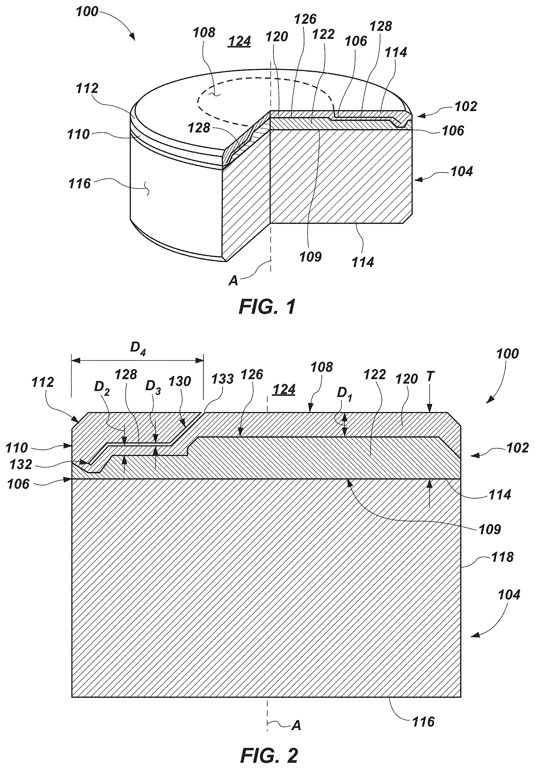
[0007] FIG. 1 is a partial cutaway perspective view of a cutting element 100 for an earth-boring tool. The cutting element 100 may include a cutting table 102 secured to a substrate 104.
[0008] FIG. 2 is a cross-sectional view of the cutting element of FIG. 1;
[0009] FIG. 3 is a simplified drawing illustrating how a microstructure of a first region of the cutting table of the cutting element of FIGS. 1 and 2 may appear under magnification and illustrates the substantial absence of catalyst material in interstitial spaces among interbonded grains of superabrasive material in the first region of the cutting table;
[0010] FIG. 4 is a simplified drawing illustrating how a microstructure of a second region of the cutting table of the cutting element of FIGS. 1 and 2 may appear under magnification and illustrates the presence of catalyst material in interstitial spaces among interbonded grains of superabrasive material in the second region of the cutting table;
[0011] FIG. 5 is a cross-sectional view of another embodiment of a cutting element in accordance with this disclosure;
[0012] FIG. 6 is a cross-sectional view of another embodiment of a cutting element in accordance with this disclosure;
[0013] FIG. 7 is a cross-sectional view of another embodiment of a cutting element in accordance with this disclosure;
[0014] FIG. 8 is a flowchart diagram of a method for forming the cutting element of FIG. 1;
[0015] FIG. 9 is a cross-sectional view of a first intermediate product during a first stage in the method of forming the cutting element of FIG. 8;
[0016] FIG. 10 is a cross-sectional view of a second intermediate product during a second stage in the method of forming the cutting element of FIG. 8;
[0017] FIG. 11 is a cross-sectional view of a third intermediate product during a third stage in a method of forming the cutting element of FIG. 6;
[0018] FIG. 12 is a cross-sectional view of another embodiment of a third intermediate product during the third stage in a method of forming the cutting element of FIG. 7;
[0019] FIG. 13 is a perspective view of an earth-boring tool including one or more cutting elements in accordance with this disclosure;
[0020] FIG. 14 is a photograph surface view of a cutting face of a cutting element in accordance with this disclosure; and
[0021] FIG. 15 is a photograph cross-sectional view of a cutaway portion of the cutting element of FIG. 14.
DETAILED DESCRIPTION
[0022] The illustrations presented in this disclosure are not meant to be actual views of any particular cutting element, microstructure for a material, earth-boring tool, or component thereof, but are merely idealized representations employed to describe illustrative embodiments. Thus, the drawings are not necessarily to scale.
[0023] Disclosed embodiments relate generally to techniques for producing a desired leach profile within a cutting table of a cutting element of an earth-boring tool. More specifically, disclosed are embodiments of techniques for producing a desired leach profile within a cutting table involving providing a sacrificial material in a precursor material, forming the cutting table, and leaching the sacrificial material and a portion of catalyst material from the cutting table. The sacrificial material may provide a higher-rate passageway for leaching agent to flow from an exterior of the cutting table toward an interior, removing the sacrificial material and catalyst material in such a way that a resulting profile of the catalyst material remaining in the cutting table may have a shape different from a profile of the cutting table itself.
[0024] As used herein, the terms "substantially" and "about" in reference to a given parameter, property, or condition means and includes to a degree that one of ordinary skill in the art would understand that the given parameter, property, or condition is met with a degree of variance, such as within acceptable manufacturing tolerances. For example, a parameter that is substantially or about a specified value may be at least about 90% the specified value, at least about 95% the specified value, at least about 99% the specified value, or even at least about 99.9% the specified value.
[0025] As used herein, the terms "earth-boring tool" means and includes any type of bit or tool used for drilling during the formation or enlargement of a wellbore in a subterranean formation. For example, earth-boring tools include fixed-cutter bits, roller cone bits, percussion bits, core bits, eccentric bits, bi-center bits, reamers, mills, drag bits, hybrid bits (e.g., rolling components in combination with fixed cutting elements), and other drilling bits and tools known in the art.
[0026] As used herein, the term "superabrasive material" means and includes any material having a Knoop hardness value of about 3,000 Kgf/mm.sup.2 (29,420 MPa) or more. Superabrasive materials include, for example, diamond and cubic boron nitride. Superabrasive materials may also be characterized as "superhard" materials.
[0027] As used herein, the term "polycrystalline material" means and includes any structure comprising a plurality of grains (i.e., crystals) of material that are bonded directly together by inter-granular bonds. The crystal structures of the individual grains of the material may be randomly oriented in space within the polycrystalline material.
[0028] As used herein, the terms "inter-granular bond" and "interbonded" mean and include any direct atomic bond (e.g., covalent, metallic, etc.) between atoms in adjacent grains of superabrasive material.
[0029] As used herein, terms of relative positioning, such as "above," "over," "under," and the like, refer to the orientation and positioning shown in the figures. During real-world formation and use, the structures depicted may take on other orientations (e.g., may be inverted vertically, rotated about any axis, etc.). Accordingly, the descriptions of relative positioning must be reinterpreted in light of such differences in orientation (e.g., resulting in the positioning structures described as being located "above" other structures underneath or to the side of such other structures as a result of reorientation).
[0030] FIG. 1 is a partial cutaway perspective view of a cutting element 100 for an earth-boring tool. The cutting element 100 may include, for example, a cutting table 102 secured to an end of a substrate 104 at an interface 106. In additional embodiments, the cutting table 102 may be formed and/or employed without the substrate 104. The cutting element 100 may be generally cylindrical or disc-shaped, as shown in FIG. 1. In other embodiments, the cutting element 100 may have a different shape, such as a dome, cone, or chisel shape.
[0031] The substrate 104 may have a first end surface 114, a second end surface 116, and a generally cylindrical lateral side surface 118 extending from the first end surface 114 to the second end surface 116. The first end surface 114 and the second end surface 116 shown in FIG. 1 are substantially planar. In other embodiments, the first end surface 114 and/or the second end surface 116 (and, hence, the interface 106 between the substrate 104 and the cutting table 102) may be non-planar.
[0032] The substrate 104 may be formed of and include a hard, wear-resistant material suitable for the downhole environment. By way of nonlimiting example, the substrate 104 may be formed from and include a ceramic-metal composite material (i.e., a "cermet" material). More specifically, the substrate 104 may be formed of and include, for example, a matrix-cemented carbide material, such as matrix-cemented tungsten carbide material, in which tungsten carbide particles are cemented together in a metallic matrix material (sometimes referred to in the art as a "binder"). As used herein, the term "tungsten carbide" means any material composition that contains chemical compounds of tungsten and carbon, such as, for example, WC, W.sub.2C, and combinations of WC and W.sub.2C. Tungsten carbide includes, for example, cast tungsten carbide, sintered tungsten carbide, and macrocrystalline tungsten carbide. The metallic matrix material may include, for example, a catalyst material for catalyzing intergranular bonds among grains of superabrasive material. More specifically, the metallic matrix material may include, for example catalyst materials including Group VIII-A metals and alloys including Group VIII-A metals (e.g., cobalt, nickel, iron, alloys and/or mixtures thereof). Such catalyst materials may be referred to in the art as "metal solvent catalysts." As a specific, nonlimiting example, the substrate 104 may be formed of and include a cobalt-cemented tungsten carbide material.
[0033] The cutting table 102 may be disposed on or over the first end surface 114 of the substrate 104. The cutting table 102 may include a volume of interbonded grains of superabrasive material, and may have a first major surface 108 defining a cutting face of the cutting table 102, a second major surface 109 on an opposite side of the cutting table 102, and at least one lateral side surface 110 extending from the second major surface 109 toward the first major surface 108. The second major surface 109 of the cutting table 102 may abut against the first end surface 114 of the substrate 104 at the interface 106. A longitudinal axis A may extend through a geometric center of the cutting table 102 in a direction at least substantially perpendicular to the first major surface 108.
[0034] The cutting table 102 may also include a chamfer surface 112 at a periphery of the first major surface 108 in some embodiments. The chamfer surface 112 shown in FIG. 1 extends at an oblique angle from the first major surface 108 to the lateral side surface 110 in the embodiment of FIG. 1, although the cutting table 102 may have additional chamfer surfaces, and such chamfer surfaces may be oriented at a series of oblique angles from the first major surface 108 to the lateral side surface 110. As an alternative, one or more surfaces of the cutting table 102 may be rounded or comprise a combination of at least one chamfer surface and at least one arcuate surface.
[0035] The lateral side surface 110 of the cutting table 102 may be at least substantially flush with the lateral side surface 118 of the substrate 104, and the cutting face 108 of the cutting table 102 may be oriented at least substantially parallel to the first end surface 114 of the substrate 104. The cutting table 102 may be generally cylindrical or disc-shaped. In other embodiments, the cutting table 102 may have a different shape, such as a dome, cone, or chisel shape. In embodiments where the cutting table 102 is cylindrical, the cutting table 102 may have a thickness T, as measured in a direction at least substantially parallel to the longitudinal axis A, of between about 1 mm and about 4 mm (e.g., between about 1.5 mm and about 3.0 mm). As a specific, nonlimiting example, the cutting table 102 may have a thickness T in of between about 1.8 mm and about 2.2 mm (e.g., about 2 mm). As used herein, ranges characterized as being between two values shall be interpreted to include those values and all values therebetween. For example, a range between 1 and 4 shall include 1, 4, and all values between 1 and 4.
[0036] The cutting table 102 may include, for example, interbonded grains of diamond or cubic boron nitride. The superabrasive material may make up, for example, more than about 70% by volume of the cutting table 102. More specifically, grains of the superabrasive material may occupy between about 70% and about 90% (e.g., about 80%) by volume of the cutting table 102.
[0037] Interstitial spaces among the interbonded grains of superabrasive material in one or more first regions 120 of the cutting table 102 may be at least substantially devoid of solid infiltrated material, the interstitial spaces in such first regions 120 being occupied by environmental fluid (e.g., air). The interstitial spaces may be occupied by (e.g., filled with) a solid infiltrated material (e.g., a catalyst material) in one or more second regions 122 of the cutting table 102. At least one of the first regions 120 of the cutting table 102 at least substantially devoid of solid infiltrated material in the interstitial spaces may be located proximate to the exterior 124 of the cutting table 102. For example, one or more first regions 120 may extend from one or more of the first major surface 108, the chamber surface 112, and the lateral side surface 110 toward the interior of the cutting table 102. The second region(s) 122 of the cutting table 102 having solid infiltrated material in the interstitial spaces may be located within the interior of the cutting table 102, and at least one first region 120 of the cutting table 102 at least substantially devoid of solid infiltrated material in the interstitial spaces may be interposed between each second region 122 having solid infiltrated material in the interstitial spaces and the exterior 124.
[0038] FIG. 2 is a cross-sectional view of the cutting element 100 of FIG. 1. A profile of the second region(s) 122 of the cutting table 102, as viewed in a plane at least substantially perpendicular to the first major surface 108, may be different from a profile of the cutting table 102. For example, a cross-sectional shape of the cutting table 102 as defined by the first major surface 108, the chamfer surface(s) 112, the lateral side surface 110, and the second major surface 109 may be rectangular with chamfered corners on one side, as shown in the embodiment of FIG. 2. A cross-sectional shape of the second region(s) 122 of the cutting table 102, as defined by at least a portion of the second major surface 109 and a boundary 126 between the second region(s) 122 having solid infiltrated material in the interstitial spaces and the first region(s) 120 at least substantially devoid of solid infiltrated material in the interstitial spaces, may be, for example, in the shape of a stepped pyramid or undulating series of plateaus in the embodiment of FIG. 2. In other embodiments, the cross-sectional shape of the second region(s) 122 of the cutting table 102 having solid infiltrated material in the interstitial spaces may have other shapes differing from shrunken versions of the cross-sectional shape of the cutting table 102.
[0039] For example, a first distance Di between at least the first major surface 108 of the cutting table 102 and the boundary 126 between the first region(s) 120 and the second region(s) may not be constant (e.g., may vary across the first major surface 108 of the cutting table 102). More specifically, the first distance Di between the first major surface 108 and the boundary 126, the first distance Di between the lateral side surface 110 and the boundary 126, or both may vary with radial distance from the longitudinal axis A, with angular distance around the longitudinal axis A, or both. In some embodiments, the cross-sectional shape of the second region(s) 122 of the cutting table 102 having solid infiltrated material in the interstitial spaces may be rotationally symmetrical about the longitudinal axis A, reflexively symmetrical about at least one plane intersecting the longitudinal axis A, or both. In other embodiments, the cross-sectional shape of the second region(s) 122 of the cutting table 102 may be rotationally asymmetrical about the longitudinal axis A, reflectively asymmetrical about at least one plane intersecting the longitudinal axis A, or both.
[0040] To enable formation of such geometries for the second region(s) 122 of the cutting table 102 having solid infiltrated material in the interstitial spaces among interbonded grains of the polycrystalline, superabrasive material, the first region(s) 120 of the cutting table 102 at least substantially lacking solid infiltrated material may include passageways 128 extending from the exterior 124 of the cutting table 102, partially through the first region(s) 120, toward the substrate 104. For example, one or more passageways 128 may extend from the first major surface 108, partially through the first region(s) 120, to locations spaced from the substrate 104 by about 5% or more of the thickness T of the cutting table 102. More specifically, one or more passageways 128 may extend from the first major surface 108, partially through the first region(s) 120, to locations spaced from the substrate 104 by between about 10% and about 50% (e.g., about 25%) of the thickness T of the cutting table 102. As another example, one or more passageways 128 may extend from the lateral side surface 110, partially through the first region(s) 120, to locations within the first region(s) 120 spaced from the boundary 126 between the first region(s) 120 and the second region(s) 122.
[0041] The passageway(s) 128 may take the form of, for example, tubes, channels, or other flow paths comprising spaces unoccupied by solid infiltrated material, defined by the interbonded grains of polycrystalline, superabrasive material, and having a larger average diameter than the average diameters of the interstitial spaces. Such passageway(s) 128 may enable leaching agent to which the cutting table 102 is exposed to more easily remove those materials that previously occupied the passageway(s) 128 and the interstitial spaces proximate thereto, when compared to the rate at which the leaching agent may remove material from the interstitial spaces absent the passageways 128. As a result, a second distance D.sub.2 from the passageway(s) 128 to the boundary 126 may be equal to a shortest first distance D.sub.1 between the exterior 124 and the boundary 126. In other words, the leaching depth to define the boundary 126 may generally be equal to the second distance D.sub.2, as measured from the exterior 124 of the cutting table 102 or a passageway 128 proximate to the second region 122, whichever is closest.
[0042] A shortest third distance D.sub.3 between walls 130 of the polycrystalline, superabrasive material defining the passageway(s) 128 may be, for example, between about 0.025 mm and about 1 mm. More specifically, the shortest third distance D.sub.3 between walls 130 of the polycrystalline, superabrasive material defining the passageway(s) 128 may be, for example, between about 0.05 mm and about 0.5 mm. As specific, nonlimiting examples, the shortest third distance D.sub.3 between walls 130 of the polycrystalline, superabrasive material defining the passageway(s) 128 may depend partially on what precursor structure(s) are utilized to form the passageway(s) 128, with wires of sacrificial material generally producing a shortest third distance D.sub.3 of between about 0.05 mm and about 1 mm and foils of sacrificial material generally producing a shortest third distance D.sub.3 of between about 0.025 mm and about 0.5 mm.
[0043] Terminal ends 132 of the passageway(s) 128 may be located within the cutting table 102 itself. For example, the terminal ends 132 of the passageways(s) 128 may be located within the first region 120. More specifically, the terminal end 132 of a given passageway 128 may be spaced from the substrate 104 by at least one second region 122 and a portion of the first region 120 through which the passageway 128 extends. In other embodiments, one or more passageway(s) 128 may lack "terminal" ends 132. For example, such passageway(s) 128 may include two openings 133 to the exterior 124 of the cutting table 102, the passageway(s) 128 extending from a first opening 133, into and through the first region(s) 120, back to a second opening 133.
[0044] A minimum fourth distance D.sub.4 between an opening 133 of a passageway 128 and the lateral side surface 110 of the cutting table, as measured in a radial direction perpendicular to the longitudinal axis A, may be, for example, about 5% of the maximum width W of the cutting table 102, as measured in the same direction. More specifically, the minimum fourth distance D.sub.4 between the opening 133 of a passageway 128 and the lateral side surface 110 of the cutting table 102 may be, for example, between about 5% and about 30% of the maximum width W of the cutting table 102. As a specific, nonlimiting example, the minimum fourth distance D.sub.4 between the opening 133 of a passageway 128 and the lateral side surface 110 of the cutting table 102 may be between about 10% and about 25% (e.g., about 15%) of the maximum width W of the cutting table 102. Keeping the minimum fourth distance D.sub.4 between the opening 133 of a passageway 128 and the lateral side surface 110 of the cutting table 102 above a certain amount may reduce the likelihood that stresses concentrated proximate the lateral side surface 110 (e.g., due to contact between the cutting table 102 and an underlying earth formation during removal) will result in crack propagation from and around the passageway(s) 128. Of course, the openings 133 to passageways 128 may also be located farther from the lateral side surface 110 than the minimum fourth distance D.sub.4, such as, for example, at and/or proximate to the longitudinal axis A.
[0045] FIG. 3 is a simplified drawing illustrating how a microstructure of a first region 120 of the cutting table 102 of the cutting element 100 of FIGS. 1 and 2 may appear under magnification and illustrates the substantial absence of solid infiltrant material in interstitial spaces 134 among interbonded grains 136 of superabrasive material in the first region 120 of the cutting table 102. The passageway(s) 128 may be located within the first region 120 and, as shown in FIG. 3, the shortest third distance D.sub.3 between the walls 130 defining the passageway(s) 128 may be greater than the greatest distance between interbonded grains 136 of superabrasive material defining the interstitial spaces 134.
[0046] FIG. 4 is a simplified drawing illustrating how a microstructure of a second region 122 of the cutting table 102 of the cutting element 100 of FIGS. 1 and 2 may appear under magnification and illustrates the presence of solid infiltrant material 138 in interstitial spaces 134 among interbonded grains 136 of superabrasive material in the second region 122 of the cutting table 102. The solid infiltrant material 138 may include, for example, a catalyst material for catalyzing intergranular bonds among grains 136 of superabrasive material. More specifically, the solid infiltrant material 138 may include, for example, the same material as the metallic matrix material from the substrate. As a specific, nonlimiting example, the solid infiltrant material 138 may include Group VIII-A metals and alloys including Group VIII-A metals (e.g., cobalt, nickel, iron, alloys and/or mixtures thereof).
[0047] FIG. 5 is a cross-sectional view of another embodiment of a cutting element 140 in accordance with this disclosure. In some embodiments, the shape and position of the passageway(s) 128 may enable one or more of the second region(s) 122 of the cutting table 102 including solid infiltrant material 138 in the interstitial spaces 134 among interbonded grains 136 of superabrasive material (see FIG. 4) to be located distal from the substrate 104. For example, the first region 120 may extend from the first major surface 108 of the cutting table 102, along the longitudinal axis A to one second region 122A, laterally around the one second region 122A, longitudinally past the one second region 122A, to another second region 122B located proximate to the substrate 104. The one second region 122A may be located proximate to the longitudinal axis A. For example, the longitudinal axis A may intersect with the one second region 122A, and the one second region 122A may be rotationally symmetrical about the longitudinal axis A. To enable formation of such a shape for the first region 120 and second regions 122A and 122B, the cutting table 102 may include passageways 128 extending from the first major surface 108 laterally distal from the longitudinal axis A, along the longitudinal axis A into the first region 120 proximate to the first major surface 108, radially outward toward the lateral side surface 110 above the one second region 122A, along the longitudinal axis A past the one second region 122A proximate the lateral sides of the one second region 122A.
[0048] FIG. 6 is a cross-sectional view of another embodiment of a cutting element 200 in accordance with this disclosure. The shape and position of the passageway(s) 128 may enable one or more of the second region(s) 122 of the cutting table 102 including solid infiltrant material 138 in the interstitial spaces 134 among interbonded grains 136 of superabrasive material (see FIG. 4) are located distal from the substrate 104, as with the cutting element 140 of FIG. 5. In addition, one or more of the second region(s) 122 of the cutting table 102 may be located distal from the longitudinal axis A. For example, the first region 120 may extend from the first major surface 108 of the cutting table 102, along the longitudinal axis A to the other second region 122B located proximate to the substrate 104, laterally along the other second region 122A toward a periphery of the cutting table 102, and longitudinally between the one second region 122A and the other second region 122B located proximate to the substrate 104 as the first region 120 approaches the lateral side surface 110. To enable formation of such a shape for the first region 120 and second regions 122A and 122B, the cutting table 102 may include passageways 128 extending from the first major surface 108 laterally proximate to the longitudinal axis A, along the longitudinal axis A into the first region 120 proximate to the first major surface 108, radially outward toward the lateral side surface 110 above the one second region 122A and underneath the one second region 122A proximate the lateral side surface 110 of the cutting table 102.
[0049] FIG. 7 is a cross-sectional view of another embodiment of a cutting element 202 in accordance with this disclosure. In some embodiments, the shape and position of the passageway(s) 128 may enable multiple instances of the second region(s) 122 of the cutting table 102 including solid infiltrant material 138 in the interstitial spaces 134 among interbonded grains 136 of superabrasive material (see FIG. 4) to be located distal from the substrate 104. For example, the first region 120 may extend from the first major surface 108 of the cutting table 102, along the longitudinal axis A to the other second region 122B located proximate to the substrate 104, laterally along the other second region 122A toward a periphery of the cutting table 102, longitudinally between a first instance of the one second region 122A and another instance of the one second region 122A located distal from the substrate 104 as the first region 120 approaches the lateral side surface 110, and longitudinally between the other instance of the one second region 122A and the other second region 122B located proximate to the substrate 104 as the first region 120 approaches the lateral side surface 110. To enable formation of such a shape for the first region 120 and second regions 122A and 122B, the cutting table 102 may include passageways 128 extending from the first major surface 108 laterally proximate to the longitudinal axis A, along the longitudinal axis A into the first region 120 proximate to the first major surface 108, with one set of the passageways 128 extending radially outward toward the lateral side surface 110 above the other instance of the one second region 122A and underneath the first instance of the one second region 122A proximate the lateral side surface 110 of the cutting table 102, and another set of the passageways 128 extending radially outward toward the lateral side surface 110 above the other second region 122B and underneath the other instance of the one second region 122A proximate the lateral side surface 110 of the cutting table 102. In still other embodiments, passageways 128 in accordance with this disclosure may take on other shapes and be located at other positions within the first region(s) 120, producing other shapes for the second region(s) 122.
[0050] FIG. 8 is a flowchart diagram of a method 142 for forming the cutting element 100 of FIG. 1. The method 142 may involve placing a sacrificial material 144 (see FIG. 9) among grains 136 (see FIGS. 3, 4) of superabrasive material, as shown at act 146. FIG. 9 is a cross-sectional view of a first intermediate product 148 during a first stage in the method 142 of forming the cutting element 100 of FIG. 8, generally corresponding to act 146. Referring collectively to FIGS. 8 and 9, the intermediate product 148 may include a mold 150 including one or more generally cup-shaped members 152 (e.g., defining an interior cavity 153 generally in the shape of a right cylinder or other inverse of the shapes for cutting elements described previously), which may be assembled and swaged and/or welded together to form the mold 150. The intermediate product 148 may also include the grains 136 of superabrasive material, the sacrificial material 144 partially embedded therein, a catalyst material 154, and the substrate 104 or precursor materials for forming the substrate 104 (e.g., ceramic particles and powdered metal matrix material) adjacent to the grains 136 of superabrasive material in the mold 150. The catalyst material 154 may be in the form of, for example, the metal matrix material of the substrate 104 or precursor material therefor, a foil 156 interposed between the substrate 104 or its precursor materials and the grains 136 of superabrasive material, a powder intermixed with the grains 136 of superabrasive material, or any combination or subcombination of these.
[0051] At this stage, the grains 136 may not be interbonded to one another, and may be in the form of a powder or grit. The grains 136 may have a multimodal (e.g., bimodal, trimodal, etc.) or monomodal grain size distribution, and grains 136 of different average grain sizes may be segregated into different regions of the mold 150 to impart desired characteristics to the resulting cutting table 102 (see FIG. 10).
[0052] The sacrificial material 144 may include one or both ends 158 adjacent to a wall 160 of the mold 150 and otherwise be surrounded by, and embedded within, the grains 136 of superabrasive material. The sacrificial material 144 may be positioned to form the passageways 128, and to impart a desired geometry to the second region(s) 122 upon removal of the sacrificial material 144 and a portion of catalyst material 154 from within the cutting table 102 (see FIGS. 2, 5-7). The sacrificial material 144 may take the form of, for example, a wire, foil, or sheet, and the wire, foil or sheet may include bends, curves, straight portions, or other geometries, as desired. Materials suitable for use as the sacrificial material 144 may be removable by exposure to leaching agents and may be resistant to alloying or otherwise intermixing with the catalyst material 154. For example, the sacrificial material 144 may include metals and metal alloys including 5% by weight or more rhenium (e.g., a tungsten-rhenium alloy or material mixture).
[0053] With continued reference to FIGS. 8 and 9, the method 142 may involve exposing the grains 136 of superabrasive material and the sacrificial material 144 to elevated temperature and pressure in the presence of the catalyst material 154 to form a cutting table 102 including a polycrystalline, superabrasive material, as shown at act 162. For example, a high-temperature, high-pressure (HTHP) process may be used to sinter and interbond the grains 136 of superabrasive material in the presence of the catalyst material 154 without alloying the sacrificial material 144 with the catalyst material 154. More specifically, using the HTHP process may place the catalyst material 154 into a flowable state, enabling the catalyst material 154 to flow freely among the grains 136 of superabrasive material and catalyze interbonding among the grains 136. The HTHP process may also secure the cutting table 102 to the first end surface 114 the substrate 104. Although the specific parameters of HTHP processes may vary depending on the materials used and the quantities of material in the mold 150, a pressure of at least about 5 GPa may be applied to the mold 150, while mold 150 is exposed to a temperature above about 1320.degree. C., and contents of the mold 150 may remain at peak pressure and peak temperature for at least about 5 minutes. The exact conditions may be selected to impart a desired final microstructure (e.g., the microstructures depicted in FIGS. 3 and 4) and associated properties to the resulting cutting table 102.
[0054] FIG. 10 is a cross-sectional view of a second intermediate product 164 during a second stage in the method 142 of forming the cutting element 100 of FIG. 8 generally corresponding the result of performing act 162. The second intermediate product 164 may include the cutting table 102 secured to the substrate 104. The cutting table 102 may include a single second region 122, being infiltrated throughout the interstitial spaces 138 among interbonded grains 136 of superabrasive material by the catalyst material 154 by solid infiltrant material in the form of the catalyst material 154. The cutting table 102 may also include one or more passageway(s) 128 extending from the exterior 124 of the cutting table 102, partially through thickness T of the cutting table 102 toward the substrate, as measured along the longitudinal axis A, as discussed previously. The passageways(s) 128 may be occupied by the sacrificial material 144, the sacrificial material 144 temporarily remaining within the cutting table 102 following the HTHP process.
[0055] FIG. 11 is a cross-sectional view of another second intermediate product 206 during the second stage in a method of forming the cutting element 200 of FIG. 6, and FIG. 12 is a cross-sectional view of still another embodiment of a third intermediate product 208 during the second stage in a method of forming the cutting element of FIG. 7. During the second stage shown in FIGS. 11 and 12, a protective material 204 may be positioned over at least the exposed surfaces 116 and 118 of the substrate 104, and optionally over portions of the exposed surfaces 108, 110, and 112 of the cutting table 102. More specifically, the protective material 204 may be positioned over the exposed surfaces 116 and 118 of the substrate 104 and the lateral side surface 110 of the cutting table 102, the chamfer surface 112 and the first major surface 108 (e.g., the cutting surface) of the cutting table 102 remaining free from direct contact with the protective material 204. The protective material 204 may inhibit (e.g., prevent) those surfaces that it covers from being exposed to leaching agent, reducing the likelihood that (e.g., preventing) the leaching agent from removing leachable materials from those surfaces toward the interior of the intermediate products 206 and 208. The protective material 204 may include, for example, rubber or epoxy. The protective material 204 may be formed utilizing any of the techniques for utilizing a protective material (e.g., a mask) disclosed in U.S. Pat. No. 9,534,450, issued Jan. 3, 2017, to Cheng, the disclosure of which is incorporated in this application in its entirety by this reference.
[0056] Returning to FIG. 8, the method 142 may involve removing the sacrificial material 144 and a portion of the catalyst material 154 from a first region 120 of the cutting table 102, as indicated at act 166. A remainder of the catalyst material 154 may be left within the section region 122 of the cutting table 102, as indicated at act 167. With combined reference to FIGS. 1, 2, and 8, at least a portion of the cutting table 102 may be, for example, exposed to a leaching agent, which may proceed to remove the sacrificial material 144 and the portion of the catalyst material 154 from the exterior 124 of the cutting table 102 inward, forming the first region(s) 120 and imparting a shape other than a shrunken version of the shape of the cutting table 102 to the second region(s) 122. In some embodiments, at least portions of the substrate 104, the cutting element 102, or both may be covered in a protective material 204, as described previously in connection with FIGS. 11 and 12. The intermediate products 164, 206, and 208 of FIGS. 10 through 12 (with the protective material) may be submerged or partially submerged in the leaching agent and left for a predetermined amount of time to achieve a desired leach depth. The leaching agent may include, for example, an acid or combination of acids (e.g., aqua regia). The leach time may vary from, for example, several minutes, several hours, or several days, depending on the materials used and the desired leach depths.
[0057] A rate at which the leaching agent may remove the sacrificial material 144 from within the passageway(s) 128 may be greater (i.e., faster) than a rate at which the leaching agent may remove the catalyst material 154 from the interstitial spaces 134 among interbonded grains 136 of superabrasive material in the first region(s) 120. For example, the rate at which the leaching agent removes the sacrificial material 144 from within the passageway(s) 128 may be between about 5 times and about 25 times greater than the rate at which the leaching agent removes the catalyst material 154 from the interstitial spaces 134 among interbonded grains 136 of superabrasive material in the first region(s) 120. More specifically, the rate at which the leaching agent removes the sacrificial material 144 from within the passageway(s) 128 may be, for example, between about 10 times and about 20 times (e.g., about 15 times) greater than the rate at which the leaching agent removes the catalyst material 154 from the interstitial spaces 134 among interbonded grains 136 of superabrasive material in the first region(s) 120.
[0058] The leaching agent may at least substantially completely remove the sacrificial material 144 from the passageway(s) 128 and the catalyst material 154 from the first region(s) 120. Of course, trace amounts of the sacrificial material 144, the catalyst material 154, or both may remain in the respective passageway(s) 128 and first region(s) 120 following the leaching process.
[0059] In some embodiments, to further impart a desired shape to the second region(s) 122, protective material 204 (see FIGS. 11, 12) may be positioned on one or more portions of the surfaces of the cutting table 102, such as the first major surface 108, the chamfer surface(s) 122, the lateral side surface 110, or any combination or subcombination of these. For example, any of the techniques for utilizing a protective material (e.g., a mask) to impart shape to unleached portions of a cutting table disclosed in U.S. Pat. No. 9,534,450, issued Jan. 3, 2017, to Cheng, may be used in addition to, and in combination with, the passageway(s) 128 and sacrificial materials 144 of this disclosure. In other embodiments, the cutting table 102 may be exposed to the leaching agent at least substantially without any protective material 204 (see FIGS. 11, 12) covering the surfaces of the cutting table 102 (e.g., protective material covering the substrate 104 may extend to a minor degree over the lateral side surface 110, such as covering less than about 10% of the lateral side surface 110).
[0060] FIG. 13 is a perspective view of an earth-boring tool 166 including one or more cutting elements 100, 140, 200, and/or 202 in accordance with this disclosure. The earth-boring tool 166 may include a body 168 to which the cutting element(s) 100 and/or 140 may be secured. The earth-boring tool 166 specifically depicted in FIG. 8 is configured as a fixed-cutter earth-boring drill bit, including blades 170 projecting outward from a remainder of the body 168 and defining junk slots 172 between rotationally adjacent blades 170. In such an embodiment, the cutting element(s) 100, 140, 200, and/or 202 may be secured partially within pockets 174 extending into one or more of the blades 170 (e.g., proximate the rotationally leading portions of the blades 170 as primary cutting elements 100, 140, 200, and/or 202, rotationally following those portions as backup cutting elements 100, 140, 200, and/or 202, or both). However, cutting elements 100, 140, 200, and/or 202 as described herein may be bonded to and used on other types of earth-boring tools, including, for example, roller cone drill bits, percussion bits, core bits, eccentric bits, bi-center bits, reamers, expandable reamers, mills, hybrid bits, and other drilling bits and tools known in the art.
[0061] FIG. 14 is a photograph surface view of a first major surface 108 of a cutting element 100 in accordance with this disclosure. FIG. 14 specifically depicts an opening 133 of a passageway 128 at the cutting face 108 of a cutting table 102. When forming the cutting table 102, a foil of sacrificial material including a curve extending partially radially around the longitudinal axis A of the cutting table 102 was employed to define the shape and positioning of the passageway 128 and subsequently removed, leaving the opening 133 visible in FIG. 14.
[0062] FIG. 15 is a photograph cross-sectional view of a cutaway portion of the cutting element 100 of FIG. 15. The foil of sacrificial material 144 used to form the passageway 128 of FIG. 14 also included a curve extending radially away from the longitudinal axis A as radial distance from the longitudinal axis A increased. Upon removal of the sacrificial material 144 and a portion of the catalyst material 154, the boundary 126 between the first region 120 and the second region 122 includes a curved depression or divot in the position interposed between the passageway 128 and the second region 122.
[0063] Techniques for forming leaching profiles in accordance with this disclosure may enable formation of shapes for leaching profiles not possible utilizing conventional technique, may produce leach profiles not matching cutting table profiles at lower cost and greater speed when compared to conventional techniques, and may utilize structures and materials not employed when compared to conventional structures and materials. For example, the use of sacrificial materials passageways for high-rate material removal may enable discontinuous regions of leached and unleached materials to be provided within a cutting table and may cost less and take less time to produce a desired leach profile when compared to conventional techniques.
[0064] Additional, nonlimiting embodiments within the scope of this disclosure include the following:
[0065] Embodiment 1: A cutting element for an earth-boring tool, comprising: a cutting table secured to a substrate, the cutting table comprising: a first region at least substantially free of solid infiltrant material in interstitial spaces among interbonded grains of superabrasive material located proximate a cutting face of the cutting table; a second region comprising solid infiltrant material in the interstitial spaces among the interbonded grains of the superabrasive material located proximate the substrate; and a passageway extending from an exterior of the cutting table partially through the first region; wherein a distance between the exterior of the cutting table and a boundary between the first region and the second region, as measured from a major surface of the cutting table, is not constant.
[0066] Embodiment 2: The cutting element for an earth-boring tool of Embodiment 1, wherein the passageway extends from the exterior, partially through the first region, to a locations spaced from the substrate by about 5% or more of a thickness of the cutting table, as measured along a longitudinal axis of the cutting element.
[0067] Embodiment 3: The cutting element for an earth-boring tool of Embodiment 2, wherein the passageway extends from the exterior, partially through the first region, to a location within the first region spaced from the boundary.
[0068] Embodiment 4: The cutting element of any one of Embodiments 1 through 3, wherein a shortest distance between walls defining the passageway is greater than a greatest distance between interbonded grains of superabrasive material.
[0069] Embodiment 5: The cutting element of Embodiment 4, wherein the shortest distance between walls defining the passageway is between about 0.025 mm and about 1 mm.
[0070] Embodiment 6: The cutting element of any one of Embodiments 1 through 5, wherein a terminal end of the passageway is located within the cutting table.
[0071] Embodiment 7: The cutting element of any one of Embodiments 1 through 6, wherein a minimum distance between an opening of the passageway at the exterior of the cutting table and a lateral side surface of the cutting table, as measured in a direction perpendicular to a longitudinal axis of the cutting element, is between about 5% and about 30% of a maximum width of the cutting table, as measured in the same direction.
[0072] Embodiment 8: The cutting element of any one of Embodiments 1 through 7, wherein the distance between the exterior of the cutting table and the boundary between the first region and the second region varies with radial distance from the longitudinal axis, with angular distance around the longitudinal axis, or both.
[0073] Embodiment 9: The cutting element of any one of Embodiments 1 through 8, wherein the second region is rotationally symmetrical about the longitudinal axis, reflectively symmetrical about at least one plane intersecting the longitudinal axis, or both.
[0074] Embodiment 10: An earth-boring tool, comprising: a cutting element secured to a body, the cutting element comprising: a cutting table secured to a substrate, the cutting table comprising: a first region at least substantially free of solid infiltrant material in interstitial spaces among interbonded grains of superabrasive material located proximate a cutting face of the cutting table; a second region comprising solid infiltrant material in the interstitial spaces among the interbonded grains of the superabrasive material located proximate the substrate; and a passageway extending from an exterior of the cutting table partially through the first region; wherein a distance between the exterior of the cutting table and a boundary between the first region and the second region, as measured from a major surface of the cutting table, is not constant.
[0075] Embodiment 11: A method of making a cutting element for an earth-boring tool, comprising: placing a sacrificial material among grains of a superabrasive material; exposing the grains of the superabrasive material and the sacrificial material to elevated temperature and pressure in a presence of a catalyst material, forming a cutting table including a polycrystalline, superabrasive material; removing the sacrificial material and a portion of the catalyst material from a first region of the cutting table; and leaving a remainder of the catalyst material in a second region of the cutting table.
[0076] Embodiment 12: The method of Embodiment 11, wherein placing the sacrificial material among the grains of the superabrasive material comprises placing a metal or metal alloy including 10% by weight or more rhenium among the grains of the superabrasive material.
[0077] Embodiment 13: The method of Embodiment 12, wherein placing the metal or metal alloy including 10% by weight or more rhenium among the grains of the superabrasive material comprises placing a tungsten-rhenium alloy or material mixture among the grains of the superabrasive material.
[0078] Embodiment 14: The method of any one of Embodiments 11 through 13, wherein placing the sacrificial material among the grains of the superabrasive material comprises placing a wire, foil, or sheet of the sacrificial material among the grains of the superabrasive material.
[0079] Embodiment 15: The method of Embodiment 14, wherein placing the wire, foil, or sheet of the sacrificial material among the grains of the superabrasive material comprises placing a wire, foil, or sheet including one or more of bends, curves, and straight portions among the grains of the superabrasive material.
[0080] Embodiment 16: The method of any one of Embodiments 11 through 15, wherein placing the sacrificial material among the grains of the superabrasive material comprises one or more ends of the sacrificial material adjacent to a wall of the mold and otherwise surrounding the sacrificial material in the grains of the superabrasive material.
[0081] Embodiment 17: The method of any one of Embodiments 11 through 16, further comprising removing the sacrificial material at a greater rate than a rate at which the portion of the catalyst material is removed.
[0082] Embodiment 18: The method of Embodiment 17, further comprising removing the sacrificial material at a rate between about 5 times and about 25 times greater than a rate at which the portion of the catalyst material is removed.
[0083] Embodiment 19: The method of any one of Embodiments 11 through 18, wherein removing the sacrificial material and the portion of the catalyst material comprises exposing the cutting table to a leaching agent.
[0084] Embodiment 20: The method of any one of Embodiments 11 through 19, wherein the acts of removing the sacrificial material and the portion of the catalyst material from the first region and leaving the remainder of the catalyst material in the second region comprise rendering a distance between an exterior of the cutting table and a boundary between the first region and the second region, as measured from a major surface of the cutting table, non-constant.
[0085] While certain illustrative embodiments have been described in connection with the figures, those of ordinary skill in the art will recognize and appreciate that the scope of this disclosure is not limited to those embodiments explicitly shown and described in this disclosure. Rather, many additions, deletions, and modifications to the embodiments described in this disclosure may be made to produce embodiments within the scope of this disclosure, such as those specifically claimed, including legal equivalents. In addition, features from one disclosed embodiment may be combined with features of another disclosed embodiment while still being within the scope of this disclosure, as contemplated by the inventors.
* * * * *
D00000
D00001
D00002
D00003
D00004
D00005
D00006
D00007
D00008
XML
uspto.report is an independent third-party trademark research tool that is not affiliated, endorsed, or sponsored by the United States Patent and Trademark Office (USPTO) or any other governmental organization. The information provided by uspto.report is based on publicly available data at the time of writing and is intended for informational purposes only.
While we strive to provide accurate and up-to-date information, we do not guarantee the accuracy, completeness, reliability, or suitability of the information displayed on this site. The use of this site is at your own risk. Any reliance you place on such information is therefore strictly at your own risk.
All official trademark data, including owner information, should be verified by visiting the official USPTO website at www.uspto.gov. This site is not intended to replace professional legal advice and should not be used as a substitute for consulting with a legal professional who is knowledgeable about trademark law.