Construction Machinery
KAMIMURA; Yusuke
U.S. patent application number 17/041777 was filed with the patent office on 2021-02-18 for construction machinery. This patent application is currently assigned to KOBELCO CONSTRUCTION MACHINERY CO., LTD.. The applicant listed for this patent is KOBELCO CONSTRUCTION MACHINERY CO., LTD.. Invention is credited to Yusuke KAMIMURA.
| Application Number | 20210047798 17/041777 |
| Document ID | / |
| Family ID | 1000005194336 |
| Filed Date | 2021-02-18 |


| United States Patent Application | 20210047798 |
| Kind Code | A1 |
| KAMIMURA; Yusuke | February 18, 2021 |
CONSTRUCTION MACHINERY
Abstract
A hydraulic excavator includes a lower travelling body, an upper slewing body attached to the lower travelling body in a rotatable manner about a slewing axis, distance sensors, the distance sensors being capable of detecting a distance to an object to be detected, the object being located in a circumference of the lower travelling body about the slewing axis; a slewing angle sensor that detects a slewing angle of the upper slewing body with respect to the lower travelling body; and a controller that specifies an entry prohibited area in which ingress of the lower travelling body is prohibited, based on the distance detected by the distance sensors, that generates information about safety with reference to a travelling direction of the lower travelling body based on the entry prohibited area and the slewing angle detected by the slewing angle sensor, and that outputs the information.
| Inventors: | KAMIMURA; Yusuke; (Hiroshima, JP) | ||||||||||
| Applicant: |
|
||||||||||
|---|---|---|---|---|---|---|---|---|---|---|---|
| Assignee: | KOBELCO CONSTRUCTION MACHINERY CO.,
LTD. Hiroshima-shi JP |
||||||||||
| Family ID: | 1000005194336 | ||||||||||
| Appl. No.: | 17/041777 | ||||||||||
| Filed: | February 6, 2019 | ||||||||||
| PCT Filed: | February 6, 2019 | ||||||||||
| PCT NO: | PCT/JP2019/004153 | ||||||||||
| 371 Date: | September 25, 2020 |
| Current U.S. Class: | 1/1 |
| Current CPC Class: | E02F 3/43 20130101; E02F 9/265 20130101; E02F 9/2033 20130101; E02F 9/24 20130101 |
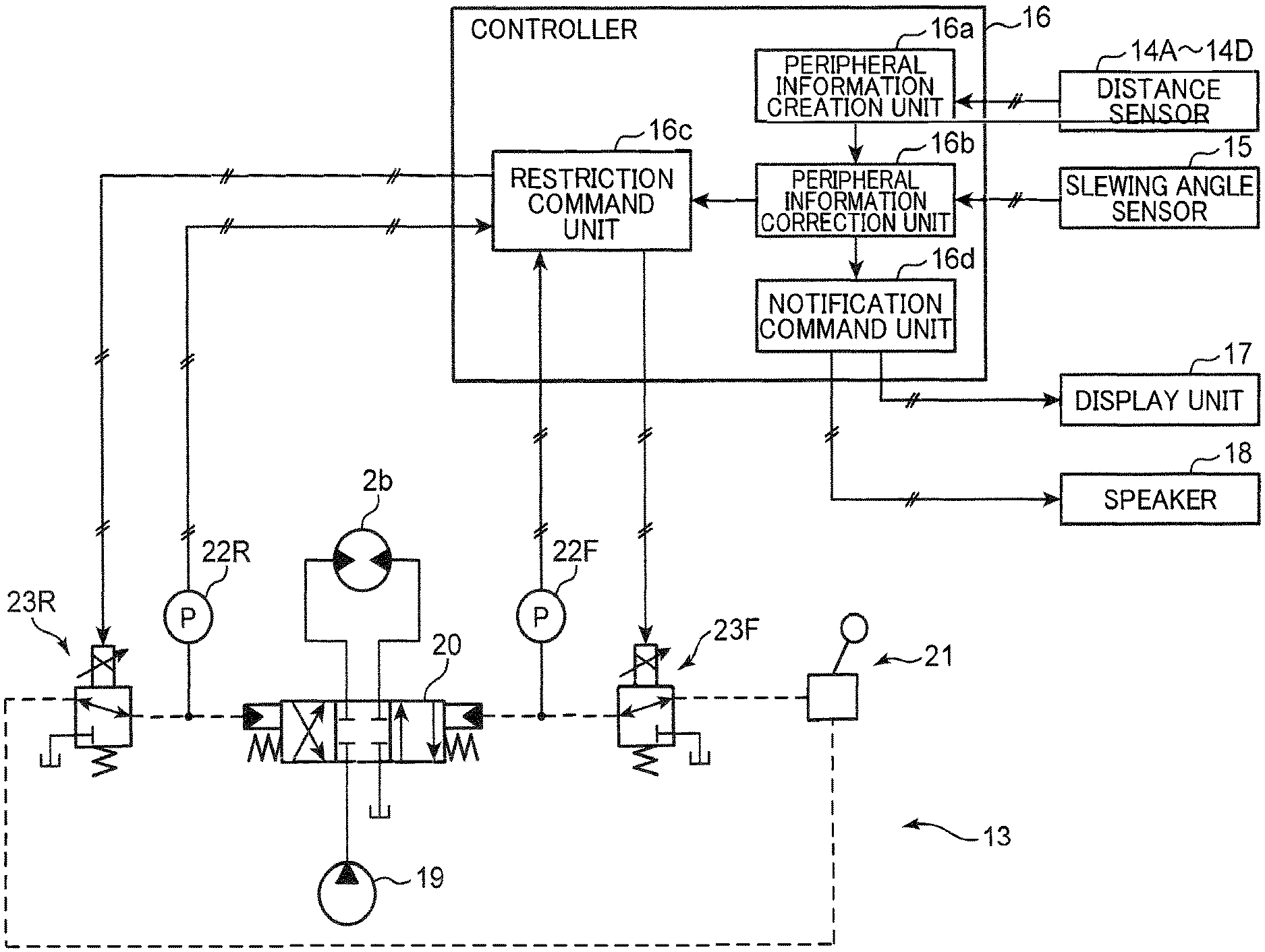
| International Class: | E02F 3/43 20060101 E02F003/43; E02F 9/20 20060101 E02F009/20; E02F 9/24 20060101 E02F009/24; E02F 9/26 20060101 E02F009/26 |
Foreign Application Data
| Date | Code | Application Number |
|---|---|---|
| Mar 29, 2018 | JP | 2018-064909 |
Claims
1. Construction machinery comprising: a lower travelling body; an upper slewing body attached to the lower travelling body in a rotatable manner about a slewing axis; distance detection means attached to the upper slewing body, the distance detection means being capable of detecting a distance to an object to be detected, the object being located in a circumference of the lower travelling body about the slewing axis; a slewing angle detector that detects a slewing angle of the upper slewing body with respect to the lower travelling body; and a controller that specifies an entry prohibited area in which ingress of the lower travelling body is prohibited, based on the distance detected by the distance detection means, that generates information about safety with reference to a travelling direction of the lower travelling body based on the entry prohibited area and the slewing angle detected by the slewing angle detector, and that outputs the information about the safety.
2. The construction machinery according to claim 1, wherein the controller determines whether the entry prohibited area exists within at least one range of a front side detection range from a front portion of the lower travelling body to a position separated by a predetermined distance to a forward side in the travelling direction, and a rear side detection range from a rear portion of the lower travelling body to a position separated by a predetermined distance to a reverse side in the travelling direction, and outputs the information about the safety when it is determined that the entry prohibition area exists within the at least one range.
3. The construction machinery according to claim 2, further comprising: a forward side restriction device that restricts travelling of the lower travelling body to a forward side in response to a command from the controller; and a reverse side restriction device that restricts travelling of the lower travelling body to a reverse side in response to a command from the controller, wherein the controller outputs a command to the forward side restriction device when it is determined that the entry prohibited area exists within the front side detection range, and outputs a command to the reverse side restriction device when it is determined that the entry prohibited area exists within the rear side detection range.
4. The construction machinery according to claim 3, wherein the controller prohibits output of a command to the reverse side restriction device when it is determined that the entry prohibited area exists only within the front side detection range, and also prohibits output of a command to the forward side restriction device when it is determined that the entry prohibited area exists only within the rear side detection range.
5. The construction machinery according to claim 3, wherein the controller is capable of outputting a command for stopping the lower travelling body with gradual deceleration to the forward side restriction device and the reverse side restriction device.
6. The construction machinery according to claim 1, further comprising: notification means for notifying an operator of predetermined information, wherein when it is determined that the entry prohibited area exists within the at least one range, the controller outputs, to the notification means, a command for notifying the operator of the determination.
Description
TECHNICAL FIELD
[0001] The present invention relates to construction machinery capable of detecting an entry prohibited area in a travelling direction.
BACKGROUND ART
[0002] Conventionally, known examples of the construction machinery include a loading work machine described in Patent Literature 1.
[0003] This loading work machine includes a loading work machine main body, a travelling unit that causes the loading work machine main body to travel, and a loader bucket provided in the loading work machine main body.
[0004] The loading work machine also includes a multi-lens camera attached to a position overlooking a travelling direction of the loading work machine main body. The multi-lens camera has a plurality of cameras disposed at a predetermined interval and can simultaneously image the same subject.
[0005] The loading work machine further includes a distance image generation unit that generates a distance image including distance information from the multi-lens camera to the subject based on an image captured by the multi-lens camera and a parallax between the cameras, a cliff edge recognition unit that recognizes a cliff edge based on the distance image, and a control unit that stops travelling of the loading work machine when a distance from the multi-lens camera to the cliff edge approaches a predetermined value or more.
[0006] The loading work machine described in Patent Literature 1 has a travelling direction of the travelling unit, being aligned with a detection direction of the multi-lens camera.
[0007] However, when a multi-lens camera is used in another construction machinery including a lower travelling body and an upper slewing body provided on the lower travelling body in a rotatable manner, the multi-lens camera has difficulty in attaching to the lower travelling body due to the following reasons.
[0008] First, the lower travelling body has a high possibility of being covered with water or earth and sand, so that attaching a multi-lens camera to the lower travelling body may cause early deterioration of the multi-lens camera.
[0009] Secondly, the lower travelling body is attached to the upper slewing body in a rotatable manner, so that disposing the multi-lens camera on the lower travelling body requires an electrical connection means (e.g., a slip ring) to be provided in a portion between the multi-lens camera and the control unit provided in the upper slewing body, thereby complicating structure of the construction machinery.
[0010] Thus, providing the multi-lens camera on the upper slewing body is conceivable, but this case may cause the multi-lens camera to have a detection direction that is not aligned with a travelling direction of the lower travelling body depending on a slewing angle of the upper slewing body.
[0011] This causes the control unit to be unable to accurately specify an entry prohibited area (a cliff edge in Patent Literature 1) in the travelling direction of the lower travelling body, so that a command for stopping travel of the loading work machine cannot be accurately output.
CITATION LIST
Patent Literature
[0012] Patent Literature 1: JP H11-222882 A
SUMMARY OF INVENTION
[0013] It is an object of the present invention to provide construction machinery having a controller capable of outputting information about safety based on a travelling direction of a lower travelling body regardless of a slewing angle of an upper slewing body.
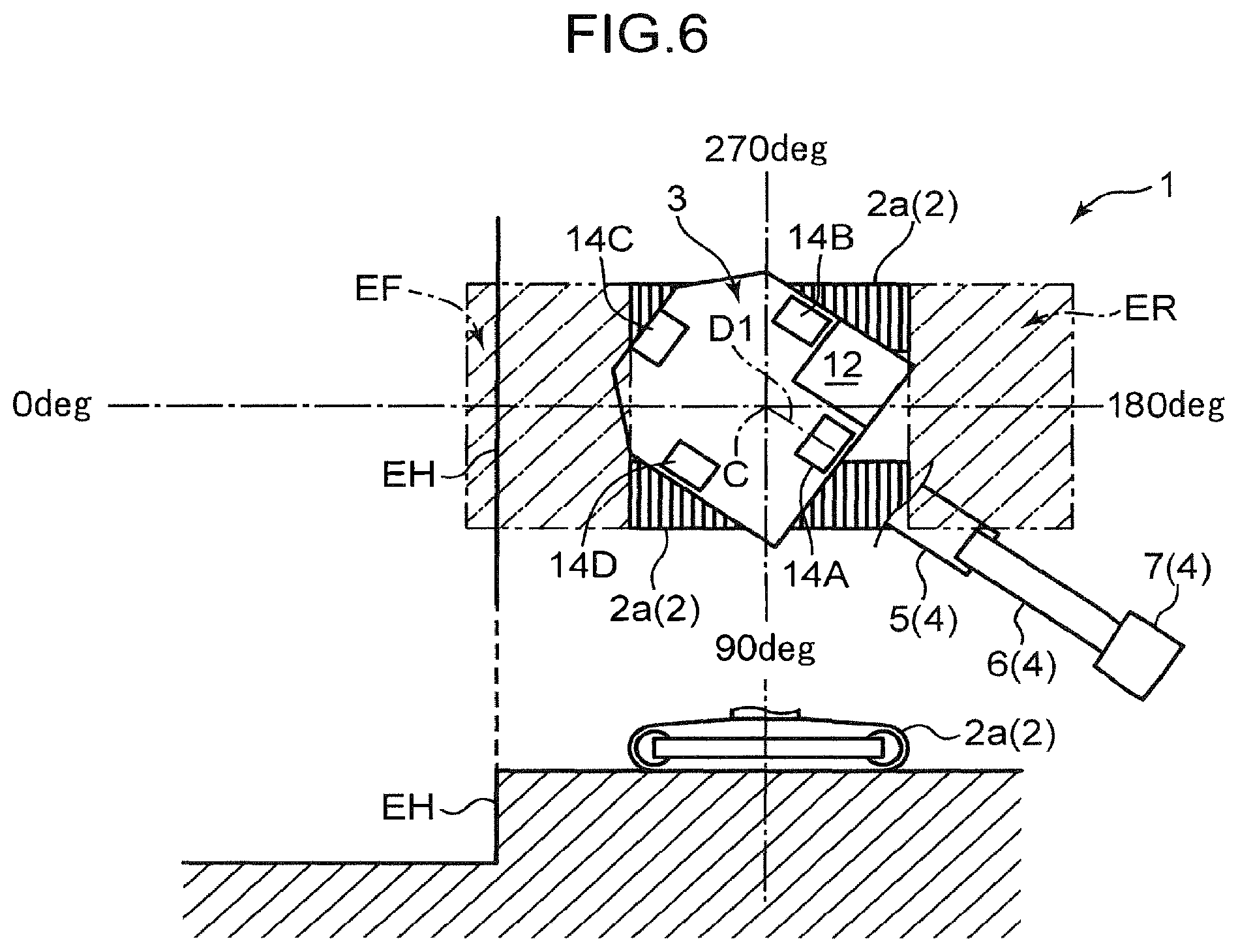
[0014] To solve the above-mentioned problems, the present invention provides construction machinery including: a lower travelling body; an upper slewing body attached to the lower travelling body in a rotatable manner about a slewing axis; distance detection means attached to the upper slewing body, the distance detection means being capable of detecting a distance to an object to be detected, the object being located in a circumference of the lower travelling body about the slewing axis; a slewing angle detector that detects a slewing angle of the upper slewing body with respect to the lower travelling body; and a controller that specifies an entry prohibited area in which ingress of the lower travelling body is prohibited, based on the distance detected by the distance detection means, that generates information about safety with reference to a travelling direction of the lower travelling body based on the entry prohibited area and the slewing angle detected by the slewing angle detector, and that outputs the information about the safety.
[0015] The present invention enables providing construction machinery having a controller capable of outputting information about safety with reference to a travelling direction of the lower travelling body regardless of a slewing angle of the upper slewing body.
BRIEF DESCRIPTION OF DRAWINGS
[0016] FIG. 1 is a side view illustrating overall structure of a hydraulic excavator according to an embodiment of the present invention.
[0017] FIG. 2 is a plan view schematically illustrating the hydraulic excavator of FIG. 1.
[0018] FIG. 3 is a system configuration diagram illustrating a travelling control device provided in the hydraulic excavator of FIG. 1 and a controller for controlling the travelling control device.
[0019] FIG. 4 is a flowchart illustrating a process executed by the controller of FIG. 3.
[0020] FIG. 5 is a combination of a plan view and a side view illustrating a state in which the hydraulic excavator of FIG. 1 moves away from an entry prohibited area.
[0021] FIG. 6 is a combination of a plan view and a side view illustrating a state in which the hydraulic excavator of FIG. 1 approaches an entry prohibited area.
[0022] FIG. 7 is a schematic diagram illustrating an image displayed on a display unit of FIG. 3.
DESCRIPTION OF EMBODIMENTS
[0023] Hereinafter, embodiments of the present invention will be described with reference to the accompanying drawings. The following embodiments are merely examples embodying the present invention, and do not limit the technical scope of the present invention.
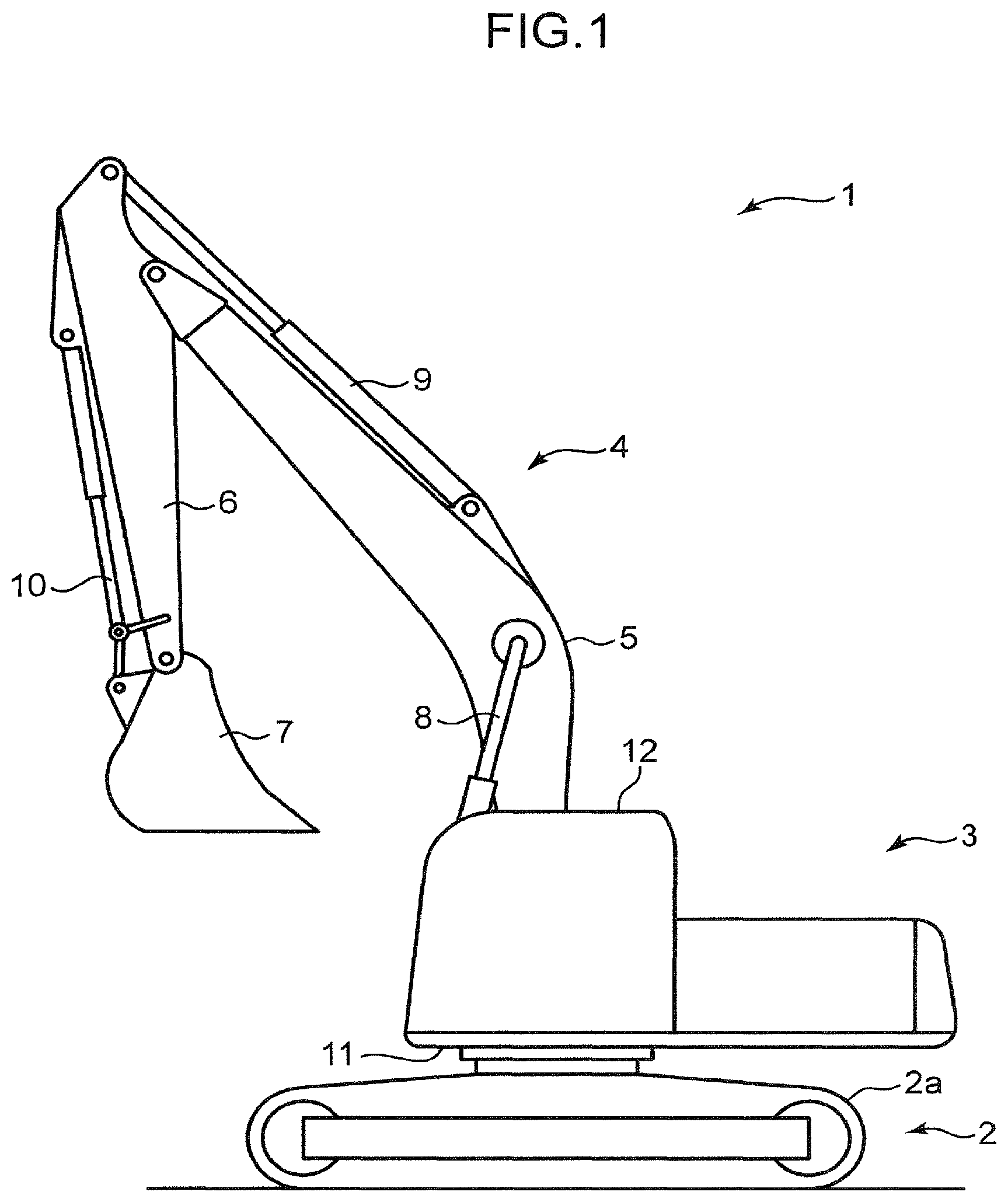
[0024] FIG. 1 is a side view illustrating overall structure of a hydraulic excavator 1 as an example of construction machinery according to an embodiment of the present invention. FIG. 2 is a plan view schematically illustrating the hydraulic excavator 1 of FIG. 1.
[0025] Referring to FIGS. 1 and 2, the hydraulic excavator 1 includes a lower travelling body 2 having a crawler 2a, an upper slewing body 3 attached to the lower travelling body 2 in a rotatable manner about a slewing axis C, and an attachment 4 attached to the upper slewing body 3.
[0026] The attachment 4 includes a boom 5 having a base end portion rotatably attached to the upper slewing body 3, and an arm 6 having a base end portion rotatably attached to a leading end portion of the boom 5, and a bucket 7 rotatably attached to a leading end portion of the arm 6.
[0027] The attachment 4 also includes a boom cylinder 8 that rotates the boom 5 with respect to the upper slewing body 3, an arm cylinder 9 that rotates the arm 6 with respect to the boom 5, and a bucket cylinder 10 that rotates the bucket 7 with respect to the arm 6.
[0028] The upper slewing body 3 includes an upper frame 11 mounted to the lower travelling body 2 in a rotatable manner, and a cab 12 provided on the upper frame 11.
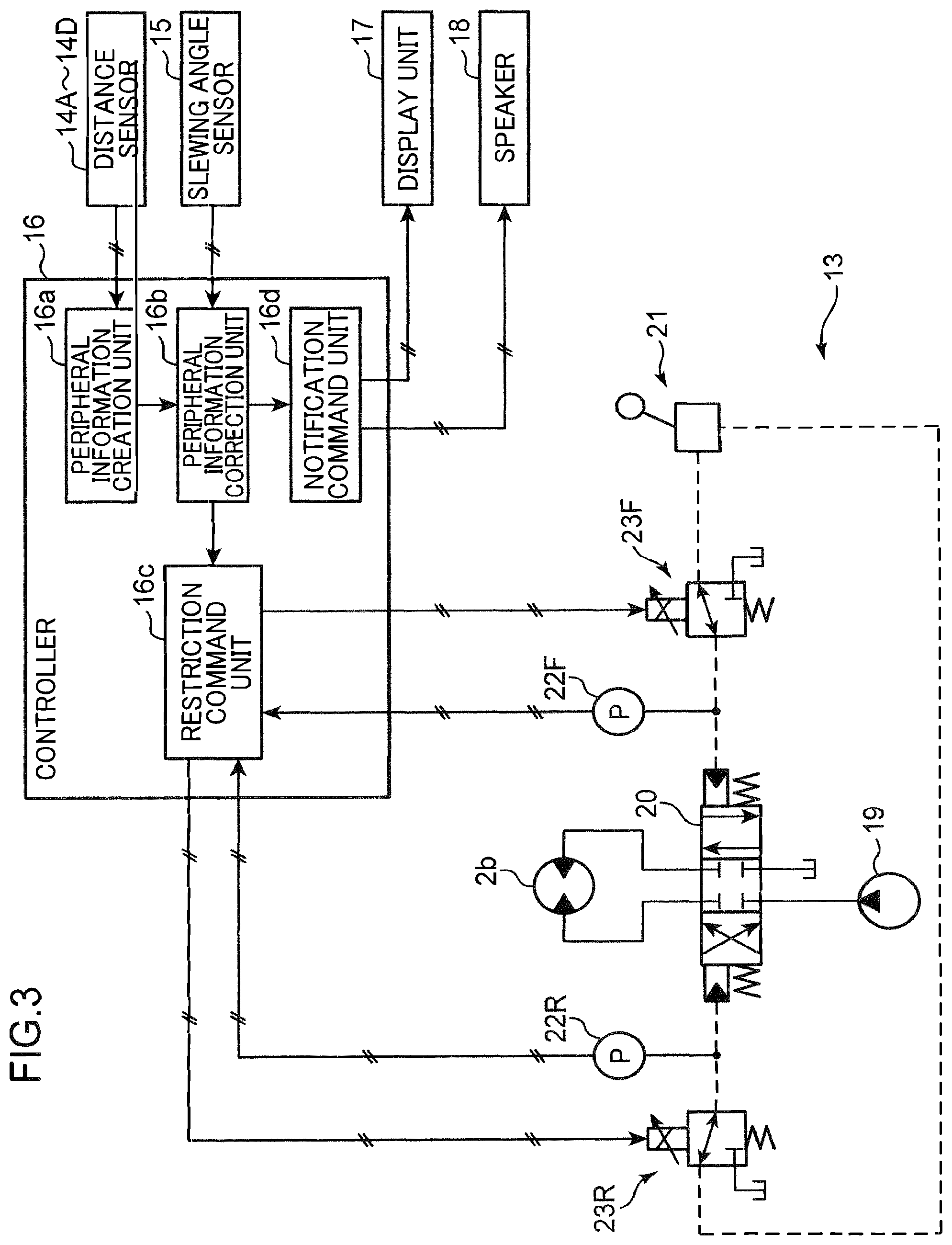
[0029] As illustrated in FIG. 3, the upper slewing body 3 also includes a travelling control device 13 that controls travelling and stop of travelling of the lower travelling body 2.
[0030] The travelling control device 13 controls driving of a travelling motor 2b provided on the crawler 2a of the lower travelling body 2. Specifically, the travelling control device 13 includes a hydraulic pump 19 that supplies hydraulic oil to the travelling motor 2b, a control valve 20 that controls supply and discharge of hydraulic oil to and from the travelling motor 2b, an operation device 21 for operating the control valve 20, and a forward side sensor 22F and a reverse side sensor 22R that detect whether the operation device 21 is operated.
[0031] The control valve 20 is a pilot-type switching valve that is switchable among a neutral position (a central position in FIG. 3) at which supply and discharge of hydraulic oil to the travelling motor 2b is stopped, a forward position (a right position in FIG. 3) at which the travelling motor 2b is operated in a forward direction, and a reverse position (a left position in FIG. 3) at which the travelling motor 2b is operated in a reverse direction. The control valve 20 includes a pilot port on forward side and a pilot port on reverse side, and is biased to the neutral position in a state where pilot pressure is not supplied to both the pilot ports.
[0032] The operation device 21 is configured by combining an operation lever, a remote control valve, and a pilot pump (each reference numeral is omitted). When the operation lever is operated, the remote control valve opens at an opening degree corresponding to the amount of the operation, and then hydraulic oil from the pilot pump is supplied to the pilot port on the forward side or reverse side of the control valve 20.
[0033] The forward side sensor 22F can detect pilot pressure applied from the operation device 21 to the pilot port on the forward side of the control valve 20, i.e., the amount of operation of the operation lever.
[0034] The reverse side sensor 22R can detect pilot pressure applied from the operation device 21 to the pilot port on the reverse side of the control valve 20, i.e., the amount of operation of the operation lever.
[0035] The travelling control device 13 includes a forward side proportional valve (forward side restriction device) 23F provided between the forward side sensor 22F and the operation device 21, and a reverse side proportional valve (reverse side restriction device) 23R provided between the reverse side sensor 22R and the operation device 21.
[0036] The forward side proportional valve 23F restricts travelling of the lower travelling body 2 to the forward side in response to a command from a controller 16 described later. Specifically, the forward side proportional valve 23F is biased to a normal position for supplying pilot pressure from the operation device 21 to the pilot port on the forward side of the control valve 20 in a state where no command is received from the controller 16. When the forward side proportional valve 23F is biased to the normal position, pilot pressure corresponding to the amount of operation of the operation lever toward the forward side is applied to the pilot port on the forward side of the control valve 20. The forward side proportional valve 23F is switched to a pressure reduction position at which the pilot pressure from the operation device 21 is reduced in response to a command from the controller 16. The forward side proportional valve 23F is configured to be able to adjust a degree of pressure reduction (the amount of hydraulic oil guided to a tank) in accordance with a command value (current value) from the controller 16. When the forward side proportional valve 23F is switched to the pressure reduction position as described above, pilot pressure applied from the operation device 21 to the pilot port on the forward side of the control valve 20 is reduced in accordance with an opening degree of the forward side proportional valve 23F, thereby restricting driving on the forward side of the travelling motor 2b.
[0037] The reverse side proportional valve 23R restricts travelling of the lower travelling body 2 to the reverse side in response to a command from the controller 16. The reverse side proportional valve 23R has a configuration similar to that of the forward side proportional valve 23F, and thus description of the configuration is omitted.
[0038] A plurality of distance sensors 14A to 14D is attached to the upper slewing body 3.
[0039] Referring to FIG. 2, the distance sensors 14A to 14D will be described below.
[0040] Each of the distance sensors 14A to 14D has a detector, and the detector emits light. Each of the distance sensors 14A to 14D detects a distance to a portion to be detected based on time from when the detector emits light to when the detector receives reflected light from an object to be detected.
[0041] The distance sensor 14A is disposed below a base end portion of the boom 5 pivotally supported by the upper frame 11 at a substantially central position in the left-right direction of a front edge of the upper frame 11. Directions of the upper slewing body 3 are each based on a direction viewed by an operator seated in a driver's seat (not illustrated) provided in the cab 12.
[0042] The distance sensor 14A has a detection range EA that spreads rightward and leftward from the distance sensor 14A toward the front. The detection range EA is set to be inclined downward from the upper frame 11 so that the distance sensor 14A can detect the ground in front of the lower travelling body 2 within the detection range EA.
[0043] The distance sensor 14B is disposed at a substantially central position in the front-rear direction of the upper frame 11 and behind the cab 12 on a left edge of the upper frame 11. The distance sensor 14B has a detection range EB that spreads forward and backward from the distance sensor 14B toward the left. The detection range EB is set to be inclined downward from the upper frame 11 so that the distance sensor 14B can detect the ground on a left side of the lower travelling body 2 within the detection range EB. The detection range EB includes a front portion overlapping a left portion of the detection range EA in plan view.
[0044] The distance sensor 14C is disposed at a substantially central position in the left-right direction of a rear edge of the upper frame 11. The distance sensor 14C has a detection range EC that spreads rightward and leftward from the distance sensor 14C toward the rear. The detection range EC is set inclined downward from the upper frame 11 so that the distance sensor 14C can detect the ground behind the lower travelling body 2 in the detection range EC. The detection range EC includes a left portion overlapping a rear portion of the detection range EB in plan view.
[0045] The distance sensor 14D is disposed at a substantially central position in the front-rear direction of the upper frame 11 and at a right edge of the upper frame 11. The distance sensor 14D has a detection range ED that spreads forward and backward from the distance sensor 14D toward the right. The detection range ED is set to be inclined downward from the upper frame 11 so that the distance sensor 14D can detect the ground on a right side of the lower travelling body 2 in the detection range ED. The detection range ED includes a rear portion overlapping a right portion of the detection range EC, and a front portion overlapping a right portion of the detection range EA in plan view.
[0046] As described above, the detection ranges EA to ED adjacent to each other of the distance sensors 14A to 14D overlap each other in plan view, so that a distance to an object to be detected can be detected, the object being located in the periphery of the lower travelling body 2 about the slewing axis C. That is, the distance sensors 14A to 14D constitute distance detection means attached to the upper slewing body 3, the distance detection means being capable of detecting a distance to an object to be detected, the object being located in the periphery of the lower travelling body 2 about the slewing axis C. Here, the object to be detected includes the ground and an object placed on the ground.
[0047] As illustrated in FIG. 3, the upper slewing body 3 includes a slewing angle sensor (slewing angle detector) 15 that detects a slewing angle of the upper slewing body 3 with respect to the lower travelling body 2.
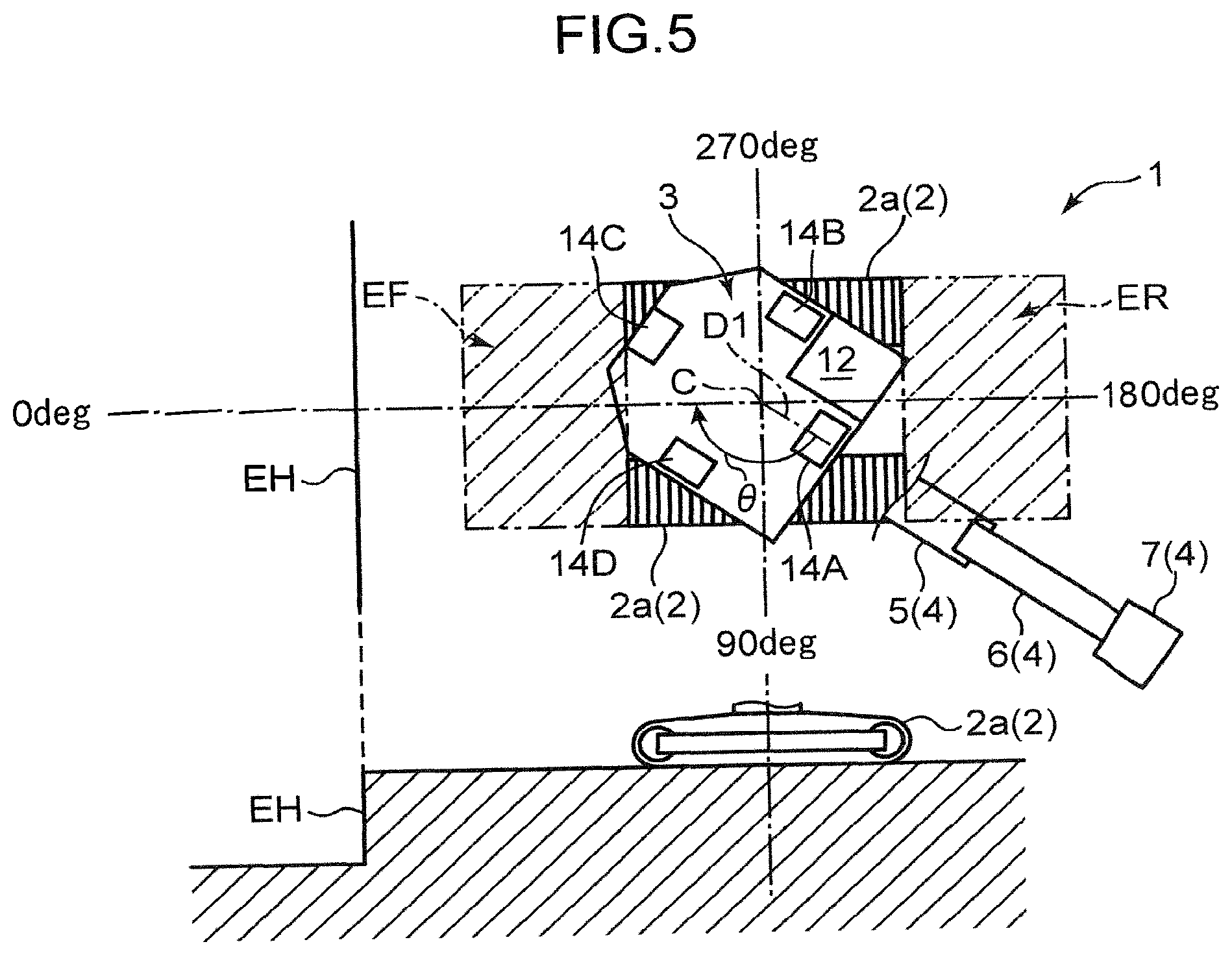
[0048] As illustrated in FIG. 5, the slewing angle sensor 15 can detect an angle of the upper slewing body 3 in a slewing body front direction D1 (a front direction of an operator seated in the driver's seat in the cab 12) with respect to a reference angle in the travelling direction of the lower travelling body 2 (indicated as a forward direction of 0 deg in the present embodiment). As the slewing angle sensor 15, for example, a rotary encoder that detects a rotation angle of a rotating shaft (not illustrated) for slewing that connects the lower travelling body 2 and the upper slewing body 3 can be used.
[0049] As illustrated in FIG. 3, the upper slewing body 3 further includes the controller 16 that specifies an entry prohibited area EH (refer to FIG. 5) in which ingress of the lower travelling body 2 is prohibited, based on distances detected by the distance sensors 14A to 14D described above, generates information about safety with reference to a travelling direction of the lower travelling body 2 based on the entry prohibited area EH and a slewing angle detected by the slewing angle sensor 15, and outputs this information. Here, the entry prohibited area EH means an area including a step (a height of unevenness on the ground and a height of an object placed on the ground) having a height equal to or higher than a preset height.
[0050] Specifically, the controller 16 outputs a predetermined command (information about safety) to the travelling control device 13, and a display unit 17 and a speaker 18 (an example of notification means) provided on the upper slewing body 3 (in the cab 12).
[0051] Referring to FIGS. 2, 3, and 5, the controller 16 will be described below.
[0052] The controller 16 is configured by combining a CPU, a ROM, and a RANI to achieve the following functions by the configuration.
[0053] The controller 16 includes a peripheral information creation unit 16a that creates information about the periphery of the lower travelling body 2, a peripheral information correction unit 16b that corrects the peripheral information to information with respect to the travelling direction of the lower travelling body 2, a restriction command unit 16c that outputs a command to the travelling control device 13, and a notification command unit 16d that outputs a command to the display unit 17 and the speaker 18.
[0054] The peripheral information creation unit 16a is configured such that when there is an area where a step having a height equal to or higher than a preset height over the entire circumference about the slewing axis C, i.e., when the entry prohibited area EH exists, a distance to the entry prohibited area EH is determined based on detection results of the distance sensors 14A to 14D, and then periphery information is created by summarizing information on the distance.
[0055] The peripheral information is created by the peripheral information creation unit 16a with reference to the slewing body front direction D1 (refer to FIG. 5) of the upper slewing body 3. Thus, the peripheral information correction unit 16b corrects the peripheral information into information with reference to the reference angle (0 deg) in the travelling direction of the lower travelling body 2.
[0056] Specifically, the example of FIG. 5 shows a state where the upper slewing body 3 has the slewing body front direction D1 when slewed by an angle .theta. with respect to the reference angle (0 deg) of the lower travelling body 2. In this case, the peripheral information correction unit 16b rotates reference coordinates of the peripheral information about the slewing axis C by the angle .theta.. This allows the peripheral information to coincide with the travelling direction of the lower travelling body 2.
[0057] The peripheral information correction unit 16b stores front side detection range EF from a front portion of the lower travelling body 2 to a position separated by a predetermined distance to a forward side in the travelling direction, and a rear side detection range ER from a rear portion of the lower travelling body 2 to a position separated by a predetermined distance to a reverse side in the travelling direction. Although the example of FIG. 5 illustrates the detection ranges EF and ER each having a width set equivalent to a width in a width direction of the lower travelling body 2, each of the widths of the detection ranges EF and ER may be set wider than that of the lower travelling body 2 to more reliably prevent ingress of the lower travelling body 2 into the entry prohibited area EH. No range in the width direction may be set for the detection ranges EF and ER. The detection ranges EF and ER has a boundary line therebetween that is not necessarily set to a straight line. Additionally, a distance from the front side detection range EF to the front portion of the lower travelling body 2 is set such that the lower travelling body 2 can be reliably stopped before the entry prohibited area EH when travelling restriction processing of the lower travelling body 2 described below is executed in a state where the lower travelling body 2 is travelling at the highest speed. Similarly, a distance from the rear side detection range ER to the rear portion of the lower travelling body 2 is set.
[0058] Then, the peripheral information correction unit 16b determines whether the entry prohibited area EH exists within at least one range of the front side detection range EF and the rear side detection range ER based on the corrected peripheral information.
[0059] For example, the example of FIG. 5 illustrates that the entry prohibited area EH is located in front of (outside) the front side detection range EF, and the entry prohibited area EH does not exist in the rear side detection range ER either. In this state, the peripheral information correction unit 16b determines that the entry prohibited area EH does not exist in the detection ranges EF and ER.
[0060] In contrast, the example of FIG. 6 illustrates that the entry prohibited area EH is located within the front side detection range EF. Thus, in this state, the peripheral information correction unit 16b determines that the entry prohibited area EH exists within at least one range of the detection ranges EF and ER.
[0061] As described above, when it is determined that the entry prohibited area EH exists within at least one range of the detection ranges EF and ER, the peripheral information correction unit 16b determines whether the entry prohibited area EH exists in the front side detection range EF, in the rear side detection range ER, or in both the detection ranges EF and ER.
[0062] Referring to FIG. 3, the restriction command unit 16c outputs a command (information about safety) to at least one of both the proportional valves 23F and 23R based on the detection range EF and/or the detection range ER determined that the entry prohibited area EH exists by the peripheral information correction unit 16b.
[0063] The example of FIG. 6 illustrates that the entry prohibited area EH exists within the front side detection range EF, so that forward movement of the lower travelling body 2 needs to be restricted. Thus, in this case, the restriction command unit 16c outputs a command to the forward side proportional valve 23F.
[0064] The restriction command unit 16c outputs a command to gradually decelerate the lower travelling body 2 to the proportional valves 23F and 23R so that the lower travelling body 2 stops until the lower travelling body 2 approaches a preset distance (hereinafter referred to as a stop distance) with respect to the entry prohibited area EH. Specifically, the restriction command unit 16c preliminarily stores a table set to have a command value (current value) to each of the proportional valves 23F and 23R, gradually increasing as a distance from the lower travelling body 2 to the entry prohibited area EH decreases. The stop distance is set such that when output of the command is started in a state where an operation lever of the operation device 21 is fully opeated, the lower travelling body 2 can be always stopped by time when reaching a position away from the entry prohibited area EH by the stop distance.
[0065] Instead of the above-described table, a command for stopping the lower travelling body 2 at a position with the stop distance to the entry prohibited area EH by gradually decelerating the lower travelling body 2 based on pilot pressure detected by both the sensors 22F and 22R may be determined by calculation. In this case, the restriction command unit 16c needs to receive the pilot pressure detected by both the sensors 22F and 22R as illustrated in FIG. 3. In contrast, when the table is used as described above, both the sensors 22F and 22R do not need to be connected to the restriction command unit 16c.
[0066] The notification command unit 16d outputs a command (information about safety) to the display unit 17 and the speaker 18 based on the detection range RF and/or the detection range ER determined that the entry prohibited area EH exists by the peripheral information correction unit 16b.
[0067] Specifically, as illustrated in FIG. 7, the display unit 17 displays an image showing that the entry prohibited area EH exists on at least one of the forward side and the reverse side in the travelling direction of the lower travelling body 2, in response to a command from the peripheral information correction unit 16b. FIG. 7 illustrates that a downward step (entry prohibited area EH) exists at a position on the forward side of the lower travelling body 2.
[0068] The speaker 18 notifies an operator by sound that the entry prohibited area EH exists on at least one of the forward side and the reverse side in the travelling direction of the lower travelling body 2.
[0069] Referring to FIGS. 3 and 4, processing executed by the controller 16 will be described below.
[0070] When the processing is started, detection values of the distance sensors 14A to 14D are acquired (step S1), and peripheral information about the entry prohibited area EH in the circumference of the lower travelling body 2, about the slewing axis C, is created based on the detection values of the distance sensors 14A to 14D (step S2).
[0071] Next, a detection value of the slewing angle sensor 15 is acquired to determine the slewing body front direction D1 (refer to FIG. 5) of the upper slewing body 3 (step S3). Then, the peripheral information is corrected into that with respect to the travelling direction of the lower travelling body 2 using the slewing body front direction D1 (step S4).
[0072] Specifically, the example of FIG. 5 illustrates that the slewing body front direction D1 is shifted by the angle .theta. with respect to the reference angle (0 deg) in the travelling direction of the lower travelling body 2, so that reference coordinates of the peripheral information are rotated by the angle .theta. about the slewing axis C. This allows the reference coordinates of the peripheral information to coincide with the travelling direction of the lower travelling body 2.
[0073] Then, it is determined whether the entry prohibited area EH exists within at least one range of both the detection ranges EF and ER (step S5). Here, when it is determined that the entry prohibited area EH does not exist within both the detection ranges EF and ER as illustrated in FIG. 5, the processing returns to step S1.
[0074] In contrast, referring to FIG. 4, when it is determined in step S5 that the entry prohibited area EH exists within at least one range of both the detection ranges EF and ER, a range of both the detection ranges EF and ER in which the entry prohibited EH exists is determined in subsequent steps S6 and S7.
[0075] Specifically, the front side detection range EF is determined in step S6 whether the entry prohibited area EH exists. When it is determined as YES in step S6, the rear side detection range ER is determined in step S7 whether the entry prohibited area EH exists.
[0076] When it is determined as NO in step S7, i.e., when the entry prohibited area EH exists only in the front side detection range EF as illustrated in FIG. 6, the controller 16 (restriction command unit 16c) outputs a command to only the forward side proportional valve 23F (step S8), and prohibits output of a command to the reverse side proportional valve 23R. This enables the lower travelling body 2 not only to be prevented from approaching the entry prohibited area EH by restricting forward movement of the lower travelling body 2 but also to move away (avoid) from the entry prohibited area EH by allowing reverse movement of the lower travelling body 2, when the entry prohibited area EH exists only within the front side detection range EF as illustrated in FIG. 6.
[0077] Referring to FIG. 4, when it is determined as YES in step S7, i.e., when the entry prohibited area EH exists in both the detection ranges EF and ER, the controller 16 (restriction command unit 16c) outputs commands to both the proportional valves 23F and 23R (step S9). This restricts travelling to the front side and the rear side on each of which the entry prohibited area EH exists. In this case, the hydraulic excavator 1 can be traveled after a measure such as reducing a step in the entry prohibited area EH on at least one of the front side and the rear side (a measure such as piling up sand to fill the step) is applied.
[0078] In contrast, when it is determined in step S6 that the entry prohibited area EH does not exist in the front side detection range EF, i.e., when the entry prohibited area EH exists only in the rear side detection range ER, the controller 16 (the restriction command unit 16c) outputs a command to only the reverse side proportional valve 23R (step S10) and prohibits output of a command to the forward side proportional valve 23F. This enables the lower travelling body 2 not only to be prevented from approaching the entry prohibited area EH by restricting reverse movement of the lower travelling body 2 but also to move away (avoid) from the entry prohibited area EH by allowing forward movement of the lower travelling body 2, when the entry prohibited area EH exists only within the rear side detection range ER.
[0079] Then, after steps S8 to S10, the controller 16 (the notification command unit 16d) executes a notification process of outputting a command to each of the display unit 17 and the speaker 18 (step S11) As illustrated in FIG. 7, this enables not only a position of the entry prohibited area EH with respect to the hydraulic excavator 1 to be visually notified to an operator using the display unit 17, but also approaching of the entry prohibited area EH to be auditorily transmitted to the operator using the speaker 18.
[0080] As described above, location information about the entry prohibited area EH in the circumference of the lower travelling body 2 about the slewing axis C can be acquired by the distance sensors 14A to 14D and the controller 16 This enables the controller 16 not only to generate information about safety with respect to the travelling direction of the lower travelling body 2 (commands to the proportional valves 23F and 23R, and commands to the display unit 17 and the speaker 18) by further using a slewing angle detected by the slewing angle sensor 15, but also to output the information.
[0081] Thus, for example, the information output from the controller 16 can be used to notify the operator to prevent ingress into the entry prohibited area EH and to stop travelling of the lower travelling body 2.
[0082] According to the embodiment above, the following effects can be achieved.
[0083] When the lower travelling body 2 approaches the entry prohibited area EH to some extent, a command can be output to each of the proportional valves 23F and 23R, the display unit 17, and the speaker 18. Thus, using the command enables preventing ingress of the lower travelling body 2 into the entry prohibited area EH and prompting the operator to prevent the ingress.
[0084] When the lower travelling body 2 approaches the entry prohibited area EH to some extent, travelling of the lower travelling body 2 toward the entry prohibited area EH can be restricted.
[0085] Allowing restriction of travelling in a direction away from the entry prohibited area EH enables a quick avoidance from the entry prohibited area EH.
[0086] The lower travelling body 2 is gradually decelerated from a stage, where the entry prohibited area EH enters the corresponding detection ranges EF and ER, to cause the lower travelling body 2 to stop, so that impact during braking can be reduced.
[0087] Notifying the operator of approach of the hydraulic excavator 1 to the entry prohibited area EH enables the operator to be prompted to move away from the entry prohibited area EH.
[0088] The present invention is not limited to the above embodiment, and for example, the following aspects also can be used.
[0089] Although there is exemplified distance detection means composed of the plurality of distance sensors 14A to 14D disposed with the adjacent detection ranges EA to ED overlapping each other, the configuration of the distance detection means is not limited to this. For example, the distance detection means can be composed of one distance sensor having a detection range rotatable about the slewing axis C.
[0090] When it is determined that the entry prohibited area EH exists within one of the detection ranges EF and ER, travelling (forward or reverse) on only a side where the entry prohibited area EH exists is restricted. However, both the forward and reverse travelling may be restricted.
[0091] Although stopping the lower travelling body 2 is exemplified as content of the restriction on the travelling of the lower travelling body 2 in the above embodiment, the content is not limited to the stopping. The lower travelling body 2 may be restricted to an extremely low travelling speed.
[0092] Although the method using the proportional valves 23F and 23R is described as a method for restricting travelling of the lower travelling body 2, the travelling of the lower travelling body 2 can also be restricted by restricting output of an engine (not illustrated). In this case, the controller 16 may output a command for reducing output to an ECU that controls driving of the engine.
[0093] Although the example in which the lower travelling body 2 is decelerated and then stopped is described, the lower travelling body 2 may be immediately stopped when it is determined that the entry prohibited area EH exists in at least one range of the detection ranges EF and ER.
[0094] Although the display unit 17 and the speaker 18 are illustrated as the notification means, the notification means is not limited to these. For example, a buzzer or a lamp also can be used as the notification means.
[0095] The construction machinery is not limited to the hydraulic excavator, and may be a crane, a demolition machine, or hybrid construction machinery.
[0096] The specific embodiment described above mainly includes the invention having the following configuration.
[0097] Specifically, the present invention provides construction machinery including: a lower travelling body; an upper slewing body attached to the lower travelling body in a rotatable manner about a slewing axis; distance detection means attached to the upper slewing body, the distance detection means being capable of detecting a distance to an object to be detected, the object being located in a circumference of the lower travelling body about the slewing axis; a slewing angle detector that detects a slewing angle of the upper slewing body with respect to the lower travelling body; and a controller that specifies an entry prohibited area in which ingress of the lower travelling body is prohibited, based on the distance detected by the distance detection means, that generates information about safety with reference to a travelling direction of the lower travelling body based on the entry prohibited area and the slewing angle detected by the slewing angle detector, and that outputs the information about the safety.
[0098] According to the present invention, location information about the entry prohibited area in the circumference of the lower travelling body about the slewing axis can be acquired by the distance detection means and the controller. This enables the controller to generate information about safety with reference to a travelling direction of the lower travelling body by further using the slewing angle detected by the slewing angle detector and to output the information.
[0099] Thus, for example, using the information output from the controller enables notifying the operator to prevent ingress into the entry prohibited area and stopping travelling of the lower travelling body.
[0100] In the present invention, the "object to be detected" includes the ground and an object placed on the ground. The "entry prohibited area" means an area including a step (a height of unevenness on the ground and a height of an object placed on the ground) having a height equal to or higher than a preset height.
[0101] The construction machinery is preferably configured such that the controller determines whether the entry prohibited area exists within at least one range of a front side detection range from a front portion of the lower travelling body to a position separated by a predetermined distance to a forward side in the travelling direction, and a rear side detection range from a rear portion of the lower travelling body to a position separated by a predetermined distance to a reverse side in the travelling direction, and outputs the information about the safety when it is determined that the entry prohibition area exists within the at least one range.
[0102] According to this aspect, the information about the safety can be output when the lower travelling body approaches the entry prohibited area to some extent. Thus, for example, using this information enables preventing ingress of the lower travelling body into the entry prohibited area and prompting an operator to prevent the ingress.
[0103] Specifically, the construction machinery preferably further includes a forward side restriction device that restricts travelling of the lower travelling body to a forward side in response to a command from the controller, and a reverse side restriction device that restricts travelling of the lower travelling body to a reverse side in response to a command from the controller, in which the controller outputs a command to the forward side restriction device when it is determined that the entry prohibited area exists within the front side detection range, and outputs a command to the reverse side restriction device when it is determined that the entry prohibited area exists within the rear side detection range.
[0104] According to this aspect, when the lower travelling body approaches the entry prohibited area to some extent, travelling of the lower travelling body toward the entry prohibited area can be restricted.
[0105] The "restriction" in the above aspect includes not only stopping the lower travelling body but also decelerating the lower travelling body.
[0106] Here, when it is determined that the entry prohibition area exists in the front side detection range or the rear side detection range, both forward and backward travelling may be restricted. However, this case does not enable a quick avoidance because travelling toward a direction for avoiding the entry prohibited area is also restricted.
[0107] Thus, the construction machinery is preferably configured such that the controller prohibits output of a command to the reverse side restriction device when it is determined that the entry prohibited area exists only within the front side detection range, and also prohibits output of a command to the forward side restriction device when it is determined that the entry prohibited area exists only within the rear side detection range.
[0108] According to this aspect, restriction of travelling in the direction away from the entry prohibited area is allowed, thereby enabling a quick avoidance from the entry prohibited area.
[0109] Here, the controller may output a command for immediately stopping the lower travelling body to the forward side restriction device and the reverse side restriction device. However, this case causes sudden braking in a stage where the entry prohibited area enters the detection range, thereby increasing impact at the time of stopping.
[0110] Thus, the construction machinery is preferably configured such that the controller is capable of outputting a command for stopping the lower travelling body with gradual deceleration to the forward side restriction device and the reverse side restriction device.
[0111] According to this aspect, the lower travelling body can be gradually decelerated from the stage where the entry prohibited area enters the detection range, thereby reducing impact at the time of braking.
[0112] The construction machinery may further include notification means for notifying an operator of predetermined information, in which when it is determined that the entry prohibited area exists within the at least one range, the controller may output, to the notification means, a command for notifying the operator of the determination.
[0113] According to this aspect, when the operator is notified that the construction machinery approaches the entry prohibited area, the operator can be prompted to move away from the entry prohibited area.
* * * * *
D00000
D00001
D00002
D00003
D00004
D00005
D00006
D00007
XML
uspto.report is an independent third-party trademark research tool that is not affiliated, endorsed, or sponsored by the United States Patent and Trademark Office (USPTO) or any other governmental organization. The information provided by uspto.report is based on publicly available data at the time of writing and is intended for informational purposes only.
While we strive to provide accurate and up-to-date information, we do not guarantee the accuracy, completeness, reliability, or suitability of the information displayed on this site. The use of this site is at your own risk. Any reliance you place on such information is therefore strictly at your own risk.
All official trademark data, including owner information, should be verified by visiting the official USPTO website at www.uspto.gov. This site is not intended to replace professional legal advice and should not be used as a substitute for consulting with a legal professional who is knowledgeable about trademark law.