Inductive Coupling Gap Compensation
Stout; Thomas Gattan ; et al.
U.S. patent application number 17/086282 was filed with the patent office on 2021-02-18 for inductive coupling gap compensation. The applicant listed for this patent is Evatran Group, Inc.. Invention is credited to James Brian Normann, Thomas Gattan Stout.
| Application Number | 20210046832 17/086282 |
| Document ID | / |
| Family ID | 1000005190818 |
| Filed Date | 2021-02-18 |


| United States Patent Application | 20210046832 |
| Kind Code | A1 |
| Stout; Thomas Gattan ; et al. | February 18, 2021 |
INDUCTIVE COUPLING GAP COMPENSATION
Abstract
A first inductive element including a plurality of first subcoils, each first subcoil characterized at least in part by a geometry that comprises a winding direction and a physical size is provided. The plurality of first subcoils are in electrical communication with each other, and the geometry of each first subcoil is selected to reduce a variation in an inductive coupling between the first inductive element and a second inductive element when a gap between the first inductive element and the second inductive element varies. A method of vehicle wireless power charging using the above system is also provided.
| Inventors: | Stout; Thomas Gattan; (Morrisville, NC) ; Normann; James Brian; (Holy Springs, NC) | ||||||||||
| Applicant: |
|
||||||||||
|---|---|---|---|---|---|---|---|---|---|---|---|
| Family ID: | 1000005190818 | ||||||||||
| Appl. No.: | 17/086282 | ||||||||||
| Filed: | October 30, 2020 |
Related U.S. Patent Documents
| Application Number | Filing Date | Patent Number | ||
|---|---|---|---|---|
| 15674091 | Aug 10, 2017 | |||
| 17086282 | ||||
| 62373856 | Aug 11, 2016 | |||
| Current U.S. Class: | 1/1 |
| Current CPC Class: | B60L 53/12 20190201; H01F 38/14 20130101; H02J 50/12 20160201; H02J 7/0042 20130101; H02J 50/10 20160201; H01F 27/38 20130101 |
| International Class: | B60L 53/12 20060101 B60L053/12; H02J 50/12 20060101 H02J050/12; H01F 27/38 20060101 H01F027/38; H02J 7/00 20060101 H02J007/00; H02J 50/10 20060101 H02J050/10; H01F 38/14 20060101 H01F038/14 |
Claims
1. A vehicle wireless power charging system, comprising: a controller configured to execute instructions on a non-transitory computer-readable data storage medium; a transfer coil apparatus, wherein the transfer coil apparatus has minimal coupling variation over a wide variation of a gap due to a combination of the coupling of a plurality of subcoils without adjusting current settings in an electric inverter supplying AC power; wherein the transfer coil apparatus comprises: two inductive elements magnetically coupled together, the two inductive elements comprising (i) a first inductive element that is a wireless power transmitter, and (ii) a second inductive element that is a wireless power receiver; wherein the first inductive element is comprised of a plurality of first subcoils in electrical communication with each other, each first subcoil characterized at least in part by a geometry comprising a winding direction, a number of turns, and a physical size; wherein at least one first subcoil is wound in a first direction (clockwise), at least one first subcoil is wound in a second direction that is opposite to the first direction (counter-clockwise), the locations of the plurality of first subcoils are fixed relative to each other, the physical size of the plurality of first subcoils are fixed, the physical size of the plurality of first subcoils are substantially different; wherein the second inductive element is comprised of a plurality of second subcoils in electrical communication with each other, each second subcoil characterized at least in part by a geometry comprising a winding direction, a number of turns, and a physical size; wherein the geometries of the first subcoils of the first inductive element are selected to reduce the variation in coupling between the first inductive element and the second inductive element as a function of a gap between each of the first subcoils and the second inductive element, the coupling defined as k(G,.phi.)=C.sub.ak.sub.a(G,.phi.)+C.sub.bk.sub.b(G,.phi.); where C.sub.a and C.sub.b are constants whose values depend on intrinsic properties of each subcoil when planes on which the first and second inductive elements lie are substantially parallel; and the centers of the first and second inductive elements in X and Y directions are at a fixed distance smaller than the largest physical size of either inductive element; and a Z direction gap between the first and second inductive elements varies over a large distance; and wherein the controller is in communication with first inductive element and with second inductive element.
2. A vehicle wireless power charging method, comprising the steps of: executing instructions, by a controller, on a non-transitory computer-readable data storage medium; statically optimizing inductive coupling between two inductive elements over a wide range of gaps in a wireless power transfer system without adjusting a current settings in an electric inverter supplying AC power; forming a plurality of first subcoils, each first subcoil characterized at least in part by an original geometry that comprises a winding direction, number of turns, and a physical size; providing a second inductive element; determining the couplings between each of the first sub coils individually and the second inductive element as a function of a gap between each of the first subcoils and the second inductive element; the coupling defined as k(G,.phi.)=C.sub.ak.sub.a(G,.phi.)+C.sub.bk.sub.b(G,.phi.); where C.sub.a and C.sub.b are constants whose values depend on intrinsic properties of each subcoil; adjusting the geometry of at least one of the first subcoils to a modified geometry, based on the coupling functions; electrically interconnecting the plurality of first subcoils to form a first inductive element, wherein the winding directions of at least two of the plurality of first subcoils are opposite; communicating, by the controller, with the first inductive element and with the second inductive element and; achieving a reduced variation in coupling between the first inductive element and the second inductive element when the gap varies, by using the first subcoil modified geometry in place of the original geometry through the entire range of gaps.
3. A vehicle wireless inductive power charging system, comprising: a controller configured to execute instructions on a non-transitory computer-readable data storage medium; two inductive elements magnetically coupled together, the two inductive elements comprising (i) a first inductive element that is a wireless power transmitter, and (ii) a second inductive element that is a wireless power receiver; wherein the first inductive element is comprised of a plurality of first subcoils in electrical communication with each other, each first subcoil characterized at least in part by a geometry comprising a winding direction, a number of turns, and a physical size; wherein at least one first subcoil is wound in a first direction (clockwise), at least one first subcoil is wound in a second direction that is opposite to the first direction (counter-clockwise), the locations of the plurality of first subcoils are fixed relative to each other; the physical size of the plurality of first subcoils are fixed; the physical size of the plurality of first subcoils are substantially different; wherein the second inductive element is comprised of a plurality of second subcoils in electrical communication with each other, each second subcoil characterized at least in part by a geometry comprising a winding direction, a number of turns, and a physical size; wherein the controller is in communication with first inductive element and with second inductive element; wherein the geometries of the first subcoils of the first inductive element are selected to reduce the variation in coupling between the first inductive element and the second inductive element when the planes on which the first and second inductive elements lie are substantially parallel and the centers of the first and second inductive element in X and Y directions are at a fixed distance smaller than the largest physical size of either inductive element, and a Z direction gap between the first and second inductive elements varies over a large distance; and wherein a power source is connected to the input of an electric inverter, the wireless power transmitter is connected to the output of the electric inverter, the wireless power receiver is connected to the input of a rectifier; a load is connected to the output of the rectifier; and power from the source is transferred through the inverter, magnetic coupling, and rectifier, to the load, and current settings of the electric inverter are not adjusted.
Description
CROSS-REFERENCE TO RELATED APPLICATIONS
[0001] The present disclosure is related and claims priority to U.S. Provisional Pat. Appl. No. 62/373,856, filed on Aug. 11, 2016, and U.S. patent application Ser. No. 15/674,091, filed on Aug. 10, 2017, the contents of which are hereby incorporated by reference in their entirety, for all purposes.
BACKGROUND
Field of Disclosure
[0002] Embodiments described herein are generally related to the field of wireless powering of electronic devices. More specifically, embodiments described herein are related to systems and methods for compensating an inductive coupling variation with respect to a gap variation between a primary inductor and a secondary inductor in a wireless powering configuration. One or more of these embodiments may be employed to transfer power to a vehicle from a base charging system.
Related Art
[0003] Current systems for wireless power transfer into mobile electronic appliances have wide variability in total power efficiency over the charging configuration geometry. For example, the inductive coupling between two inductive elements, each having a single coil, may vary by a factor of two or more over a span of about two inches for the gap between the two inductive elements. This inductive coupling variability is compensated by adjusting the current settings in the electric inverter supplying AC power for the primary inductive element, typically resulting in higher losses when the inductive coupling is reduced with distance.
SUMMARY
[0004] In one embodiment, a first inductive element includes a plurality of first subcoils, each first subcoil characterized at least in part by a geometry that comprises a winding direction and a physical size. The plurality of first subcoils are in electrical communication with each other, and the geometry of each first subcoil is selected to reduce a variation in an inductive coupling between the first inductive element and a second inductive element when a gap between the first inductive element and the second inductive element varies.
[0005] In another embodiment, a method of optimizing inductive coupling includes forming a plurality of first subcoils, each first subcoil characterized at least in part by a geometry that comprises a winding direction and a physical size. The method includes electrically interconnecting the plurality of first subcoils to form a first inductive element, providing a second inductive element, and determining a variation of an inductive coupling between the first inductive element and the second inductive element as a function of a gap between the first inductive element and the second inductive element. The method also includes adjusting the geometry of at least one of the first subcoils to reduce the variation of the inductive coupling when the gap varies.
BRIEF DESCRIPTION OF THE DRAWINGS
[0006] FIG. 1 illustrates an inductive wireless charging system including a first inductive element and a second inductive element having a mutual inductance M there between, according to some embodiments.
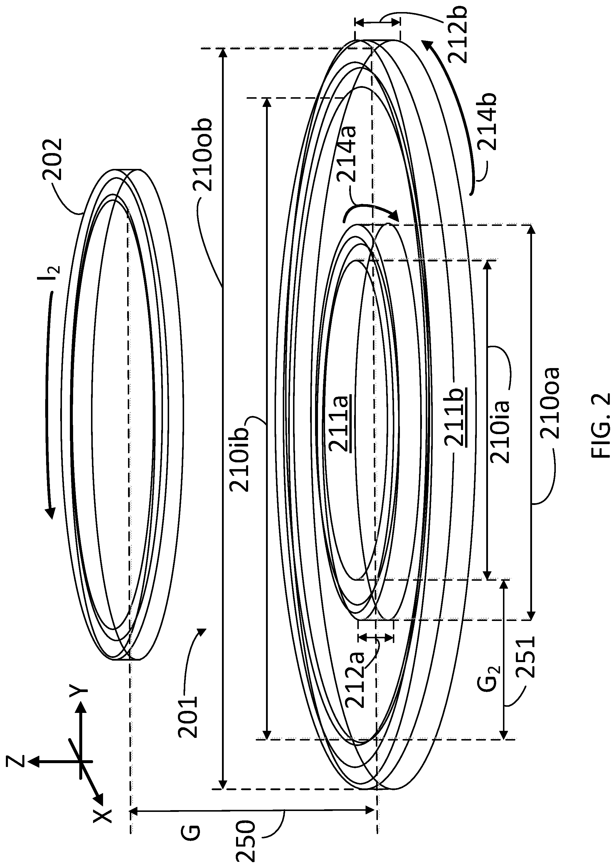
[0007] FIG. 2 illustrates a configuration between a first inductive element and a second inductive element, according to some embodiments.
[0008] FIG. 3 illustrates a chart with graphs describing a magnetic coupling as a function of a gap between the first inductive element and the second inductive element, according to some embodiments.
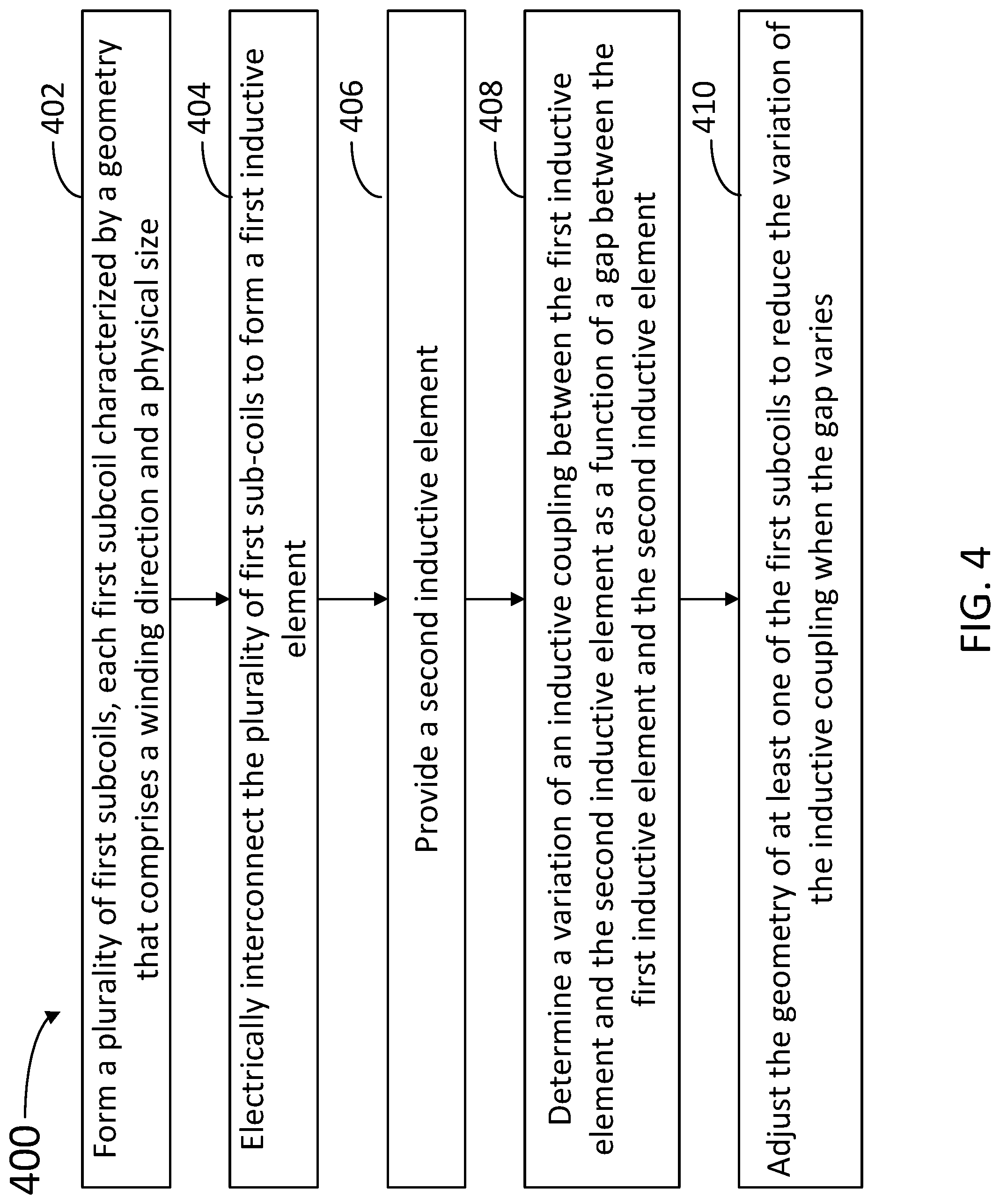
[0009] FIG. 4 is a flow chart illustrating steps in a method for inductive coupling, according to some embodiments.
[0010] In the figures, elements and steps denoted by the same or similar reference numerals are associated with the same or similar elements and steps, unless indicated otherwise.
DETAILED DESCRIPTION
[0011] The detailed description set forth below is intended as a description of various implementations and is not intended to represent the only implementations in which the subject technology may be practiced. As those skilled in the art would realize, the described implementations may be modified in various different ways, all without departing from the scope of the present disclosure. Accordingly, the drawings and description are to be regarded as illustrative in nature and not restrictive.
[0012] A wireless inductively coupled power transfer system typically includes a primary coil and a secondary coil. A traditional coil in the system is wound as a single spiral of wire, with each turn being concentric and each turn going in the same direction (e.g. clockwise or counterclockwise). In some embodiments consistent with the present disclosure, a single coil can be constructed from what is conceptually a plurality of subcoils where the winding directions are not all the same. A small diameter coil couples well at small gaps, but the inductive coupling with the primary inductor that wirelessly provides an AC power typically drops off quickly as the gap is increased. A larger diameter coil couples better across the full range (i.e. the inductive coupling does not fall off as quickly with increased gap), but will have a lower coupling coefficient at small gaps. Subcoils comprising the primary coil that are described as "large" are larger than the secondary coil. Conversely, subcoils comprising the primary coil that are described as "small" are smaller than the secondary coil. Similarly, subcoils comprising the secondary that are described as "large" or "small" are larger or smaller, respectively, than the primary coil.
[0013] FIG. 1 illustrates an inductive wireless charging system 100 including a first inductive element 101, having inductance, L.sub.1, and a second inductive element 102, having inductance, L.sub.2. First inductive element 101 and second inductive element 102 may electromagnetically interact through a mutual inductance, M, therebetween, according to some embodiments. Charging system 100 may include a configuration where a source 140, coupled to second inductive element 102 (e.g., via an inverter circuit), would typically provide power to a remote electronic device, e.g., charge a battery for an electric vehicle that includes first inductive element 101 at a voltage, V.sub.1, and generating a current, I.sub.1.
[0014] First inductive element 101 includes subcoils 111a and 111b (hereinafter, collectively referred to as "subcoils 111"). Subcoils 111 are in electrical communication with each other. Subcoil 111a may be associated with an inductance, L.sub.1a, and subcoil 111b may be associated with an inductance, L.sub.1b, so that, in some embodiments, L.sub.1=L.sub.1a+L.sub.1b (e.g., when subcoils 111 are interconnected in series as in system 100). In some embodiments, L.sub.1 and L.sub.1a, and L.sub.1b are related as: 1/L.sub.1=1/L.sub.1a+1/L.sub.1b (e.g., when subcoils 111 are interconnected in parallel). More generally, the relation between L.sub.1, L.sub.1a, L.sub.1b, and any other inductance from an additional subcoil 111 in first inductive element 101 may depend on the specific electric coupling between subcoils 111, and also on a fixed, relative angle .theta. 115 formed between axis W.sub.a of subcoil 111a and axis W.sub.b of subcoil 111b, respectively.
[0015] Subcoils 111 may include a plurality of substantially concentric loops of an electrically conductive material (e.g., a conductive wire). In some embodiments, subcoils 111 are interconnected in series. In some embodiments, subcoils 111 are interconnected in parallel. Subcoils 111 also have a physical size that may be defined by a diameter 110a and 110b (hereinafter, collectively referred to as "diameter 110") and a thickness 112a and 112b (hereinafter, collectively referred to as "thickness 112"). Further, each subcoil 111 may be characterized by a geometry that comprises a winding direction 114a and 114b (e.g., counterclockwise or clockwise) and a physical size such as diameter 110 or thickness 112. The geometry of subcoils 111 may include a number of loops, N.sub.a, and N.sub.b, in each subcoil.
[0016] In some embodiments, second inductive element 102 includes a plurality of subcoils characterized in a similar manner as subcoils 111 in first inductive element 101. Source 140 generates a voltage V.sub.2, and a current I.sub.2 flowing through second inductive element 102, at a frequency, .omega.. Voltage V.sub.2 and current I.sub.2 generate AC voltage V.sub.1 and AC current I.sub.1 through first inductive element 101, due to the mutual inductance factor, M. Accordingly, voltages V.sub.1 and V.sub.2 may satisfy the following expressions:
V.sub.1=j.omega.(L.sub.1I.sub.1+MI.sub.2) (1.1)
V.sub.2=j.omega.(MI.sub.1+L.sub.2I.sub.2) (1.2)
System 100 may include a capacitor 155 that introduces a resonant behavior in the inductive coupling of second inductive element 102 and first inductive element 101. Accordingly, for high .omega. relative to 1/C (where the impedance is 1/.omega.C), primary coil 101 is substantially shorted down to ground voltage, V.sub.g (e.g., zero). Assuming V.sub.g=0, under high frequency conditions, then, V.sub.2 is shorted down to zero and the following is true:
I 2 = - M I 1 L 2 ( 2 ) ##EQU00001##
[0017] And using Eq. (2) into Eq. 1.1:
V 1 = j .omega. ( L 1 I 1 - M 2 I 1 L 2 ) = I 1 j .omega. ( L 1 - M 2 L 2 ) ( 3 ) ##EQU00002##
[0018] By analogy with Eqs. 1.1 and 1.2, an effective inductance L.sub.s may be defined as:
L s = L 1 - M 2 L 2 Wherein ( 4 ) V 1 = I 1 j .omega. L s ( 5 ) ##EQU00003##
[0019] Accordingly, L.sub.s may be interpreted as the inductance measured across L.sub.1 when second inductor 102 is shorted (e.g., at high frequencies, .omega.). From Eq. 4, the value of the mutual inductance, M, may be found as:
M= {square root over (L.sub.2(L.sub.1-L.sub.s))} (6)
[0020] A unit-less coupling coefficient, k, may be further defined as:
k = M L 1 L 2 = ( 1 - L s L 1 ) ( 7 ) ##EQU00004##
[0021] Measurement of L.sub.s when second inductive element 102 is shorted, together with prior knowledge of L.sub.2 and L.sub.1, gives a measure of coupling coefficient, k. The coupling coefficient, k, is a unit-less value between 0 and 1, which is dependent on the geometry of each of subcoils 111, the configuration between subcoils 111 themselves, and the configuration of each subcoil 111 relative to second inductive element 102. In some embodiments, the geometry of subcoils 111 may include a size (e.g., diameter 110 and thickness 112). The configuration between subcoils 111 themselves may include a relative winding direction between the subcoils (e.g., coil 111-1 wound clockwise, and coil 111-2 wound counter-clockwise) and the value of fixed angle .theta. 115. The configuration between subcoils 111 relative to second inductive element 102 includes the value of gap 150 (G) and the value of an angle .PHI. 125 between the axes of first conductive element 101 and second conductive element 102 (W.sub.a and W.sub.2, respectively). In some embodiments, the geometry of subcoils 111 is selected to reduce a variation in the coupling coefficient, k, between first inductive element 101 and second inductive element 102 when G 150 varies, or when .PHI. 125 varies. Likewise, in embodiments where second inductive element 102 includes a plurality of subcoils, the geometry of each subcoil in the second inductive element 102 may be selected to reduce the variation in the inductive coupling between the first inductive element and the second inductive element when G 150 or .PHI. 125 vary.
[0022] In some embodiments, and to a first order approximation, it is desirable to express the inductive coupling, k, between first inductive element 101 and second inductive element 102 as a linear combination of two inductive coupling coefficients k.sub.a and k.sub.b. Accordingly, inductive coupling k.sub.a may be an inductive coupling between subcoil 111a and second inductive element 102. Likewise, inductive coupling k.sub.b may be an inductive coupling between subcoil 111b and second inductive element 102. In such embodiments, an expression for inductive coupling, k, between first inductive element 101 and second inductive element 102 may be given by the following mathematical equation
k(G,.phi.)=C.sub.ak.sub.a(G,.phi.)+C.sub.bk.sub.b(G,.phi.) (8)
Where C.sub.a and C.sub.b are constants whose value depends on intrinsic properties of each of subcoils 111a and 111b, respectively, and their relative configuration (e.g., angle .theta. 115). In some embodiments, the intrinsic properties of each of subcoils 111a and 111b may include the inductance of each subcoil 111, separately (e.g., L.sub.a and L.sub.b). For example, the value of constants C.sub.a and C.sub.b may depend on at least one of the diameter, the length, and the number of loops of each of the subcoils 111. Further, the relative ratio between constants C.sub.a and C.sub.b may depend on the relative configuration between subcoils 111. For example, the parity between constants C.sub.a and C.sub.b (C.sub.a, C.sub.b=+,+; +, -; -,+; -,-) may depend on the relative winding orientation between the subcoils (e.g., clockwise-clockwise, clockwise-counterclockwise, counterclockwise-clockwise, counterclockwise-counterclockwise). In some embodiments, an expression similar to Eq. 8 applies for any number of subcoils 111 in first inductive element 101, and a constant C.sub.i is associated with each subcoil, 111i.
[0023] As Eq. 8 indicates, coupling coefficients k, k.sub.a, and k.sub.b may be functions of G 150, and of .PHI. 125. More generally, k.sub.a and k.sub.b may be different functions of G 150 and of .PHI. 125. The variation in the coupling coefficient, k, as a function of G 150 may be expressed from Eq. 8 as:
.DELTA.k(G,.phi.)=(C.sub.ak'.sub.a(G,.phi.)+C.sub.bk'.sub.b(G,.phi.)).DE- LTA.G (9)
Where k'.sub.a and k'.sub.b are first derivatives of functions k.sub.a and k.sub.b with respect to G 150. In some embodiments, it is desirable to choose the intrinsic properties (e.g., geometry and relative configuration, including .theta. 115) of subcoils 111 so that the values of constants C.sub.a and C.sub.b are such that .DELTA.k(G,.PHI.) is minimized for a selected range of values of gap 150 (G) and of angle .PHI. 125 (cf. Eq. 9).
[0024] When G 150 changes (e.g., first inductive element 101 is displaced relative to second inductive element 102), inductive coupling, k, changes as well by an amount .DELTA.k (cf. Eq. 9). The value of .DELTA.k leads to a change in the induced voltage V.sub.1, which may induce a reduction in voltage V.sub.2 (e.g., when .DELTA.G>0). However, reducing V.sub.2 may be compensated by an increase the current I.sub.2 to maintain a constant output power, P.sub.out=V.sub.2I.sub.2, provided by source 140. However, current I.sub.2 is typically supplied by an inverter circuit having losses that are proportional to the square of the current, I.sub.2. Embodiments as disclosed herein include specially designed first inductive element 101 having a plurality of subcoils 111, each with a geometry and a winding direction 114 that minimizes the variation ink over a wide range of values of G 150 and of .PHI. 125.
[0025] Accordingly, in some embodiments consistent with the present disclosure, the inductive coupling, k, between inductive elements 101 and 102 may vary by a factor of about two or less, over a G 150 span of five inches, or more (e.g., a variability at least half or less of what would be expected between two traditional, single-coil inductive elements). This prevents the need to over-design the inverter coupled to source 140 to operate at high values of k, and allows for the system to run at a more consistent operating point over a broader range of configurations between first inductive element 101 and second inductive element 102. Accordingly, embodiments as disclosed herein reduce the power losses in the circuitry providing current I.sub.2 to second inductive element 102 (e.g., source 140).
[0026] Wireless charging system 100 may further include a controller 160 having a processor 161 configured to execute instructions from, and receive and store data in, a memory 162. Controller 160 may communicate (e.g., wirelessly or via a wire) with first inductive element 101 and with second inductive element 102, so that when processor 161 executes instructions from memory 162, controller 160 may cause wireless charging system 100 to perform steps in a method consistent with the present disclosure. In some embodiments, controller 160 causes a charge start in wireless charging system 100 according to a detected value of G 150 or .PHI. 125 (e.g., when G 150 is smaller than a first threshold, or when .PHI. 125 is smaller than a second threshold), or a combination of a value of G 150 and a value of .PHI. 125. Further, in some embodiments controller 160 may cause a charge stop in wireless charging system 100 according to a detected value of G 150 or .PHI. 125 (e.g., when G 150 is larger than a third threshold, or when .PHI. 125 is larger than a fourth threshold), or a combination of both. Further, in some embodiments controller 160 may cause wireless charging system 100 to start or stop charging according to a value of V.sub.1, V.sub.2, I.sub.1, I.sub.2, or a combination of the above. In some embodiments, processor 161 may be configured to determine a value of k, a value of .DELTA.k, or a combination of both (cf. Eqs. 8-9). Accordingly, controller 160 may cause wireless charging system 100 to start or stop charging according to the value of k, of .DELTA.k, or a combination of the two.
[0027] FIG. 2 illustrates a configuration 200 between a first inductive element 201 and a second inductive element 202 separated by a gap G (e.g., along the Z axis) 250, according to some embodiments. In some embodiments, second inductive element 202 is configured as a primary inductor in a wireless power transfer system, receiving an alternating current (AC), I.sub.2, to induce an AC voltage in first inductive element 201, which acts as a secondary inductor configured to receive power from the primary inductor (e.g., in a wirelessly re-chargeable electric appliance). First inductive element 201 includes a smaller subcoil 211a and a larger subcoil 211b (hereinafter, collectively referred to as "subcoils 211"). Subcoil 211a has an inner diameter 210ia, an outer diameter 210oa (hereinafter, collectively referred to as "diameters 210a"), a thickness 212a, and is wound in a clockwise direction 214a. Likewise, subcoil 211b has an inner diameter 210ib (hereinafter, collectively referred to as "diameters 210b"), an outer diameter 210ob, a thickness 212b, and is wound in a counter-clockwise direction 214b.
[0028] For example, in some embodiments subcoil 211a may include 25 turns with an inner diameter 210ia of about 2.5 inches, an outer diameter 210oa of about 4.25 inches, and a thickness 212a of about 0.25 inches. Further, in some embodiments subcoil 211b may include 25 turns with an inner diameter 210ib of about 9.5 inches, an outer diameter 210ob of about 11.25 inches, and a thickness 212b of about 0.25 inches.
[0029] By winding subcoils 211 in opposite directions, the combined effective inductive coupling, k, between first inductive element 201 and second inductive element 202, is associated with a difference between the inductive coupling between subcoil 211a and second inductive element 202, k.sub.a, and the inductive coupling between subcoil 211b and second inductive element 202, k.sub.b. Furthermore, by adjusting the number of turns in each coil the ratio Ca/Cb of inductive coupling coefficients of each of subcoils 211 with second inductive element 202 can be controlled. Accordingly, an effective inductive coupling, k, may be approximately: k=k.sub.b-0.5*k.sub.a (cf. Eqs. 8-9, with C.sub.a=-0.5, and C.sub.b=1), wherein k.sub.a is the inductive coupling between subcoil 211a and second inductive element 202, and k.sub.b is the inductive coupling between subcoil 211b and second inductive element 202.
[0030] Tables 1-3 below list the results for mutual inductance (M) and inductive coupling, k(G), as a function of G 150 for the inductive coupling system illustrated in configuration 200. Without limitation, and for illustrative purposes only, the variation of G 150 in Tables 1-3 is from zero (0), to seven (7) inches.
[0031] Note that the configuration of subcoils 211 in first inductive element 201 includes a fixed gap 251 (G.sub.2) between subcoil 211a and subcoil 211b, and coplanar subcoils 211 (along an XY plane). Accordingly, in some embodiments the value of G.sub.2 251 may also be adjusted to modify coefficients C.sub.a and C.sub.b (and their relative value). For example, while subcoils 211 are shown to be concentric, some embodiments may include non-concentric subcoils 211, so that G.sub.2 251 may in fact be different around the circumference of either one of subcoils 211. Moreover, in some embodiments, subcoils 211, in addition to have different diameters 210a/210b, and different winding directions 214, may be placed in different planes.
TABLE-US-00001 TABLE 1 Total inductive coupling, k Mutual Primary Secondary Inductance Inductance Inductance (H) Inductive Z .times.10.sup.-5 (H) .times.10.sup.-4 (H) .times.10.sup.-5 Coupling (inches) (201) (202) (M) (k) 7 2.02 6.94 0.895 0.075467 6 2.02 6.94 1.02 0.085772 5 2.02 6.94 1.14 0.096533 4 2.02 6.94 1.27 0.106769 3 2.02 6.94 1.37 0.115187 2 2.02 6.94 1.42 0.119404 1 2.02 6.94 1.39 0.117647 0 2.02 6.94 1.32 0.1117
TABLE-US-00002 TABLE 2 Small subcoil 211a Primary Secondary Mutual Inductance Inductance Inductance Inductive Z .times.10.sup.-5 (H) .times.10.sup.-4 (H) .times.10.sup.-5 (H) Coupling (inches) (201) (202) (M) (k) 7 2.02 1.34 0.297 0.057098 6 2.02 1.34 0.380 0.073057 5 2.02 1.34 0.491 0.09437 4 2.02 1.34 0.639 0.122869 3 2.02 1.34 0.834 0.160482 2 2.02 1.34 1.08 0.208506 1 2.02 1.34 1.37 0.264079 0 2.02 1.34 1.62 0.312451
TABLE-US-00003 TABLE 3 Large subcoil 211b Primary Secondary Mutual Inductance Inductance Inductance Inductive Z .times.10.sup.-5 (H) .times.10.sup.-4 (H) .times.10.sup.-5 (H) Coupling (inches) (201) (202) (M) (k) 7 2.02 6.34 1.19 0.10521 6 2.02 6.34 1.40 0.123324 5 2.02 6.34 1.63 0.144373 4 2.02 6.34 1.90 0.168171 3 2.02 6.34 2.20 0.19425 2 2.02 6.34 2.50 0.220711 1 2.02 6.34 2.77 0.244385 0 2.02 6.34 2.95 0.260366
[0032] FIG. 3 illustrates a chart 300 with graphs describing the inductive coupling results of configuration 200 as a function of G 150 (cf. FIG. 2 and Tables 1-3). Curve 310a corresponds to total inductive coupling, k, (cf. Table 1). Curve 310b corresponds to inductive coupling, k.sub.a, (small subcoil 211a, cf. Table 2), dropping fast as a function of G 150 from a large value at G=0. Curve 310c corresponds to inductive coupling, k.sub.b, (large subcoil 211b, cf. Table 3), dropping at a lower rate than the small inductive coupling, from a lower inductive coupling at G=0. Further, the variation of k for first inductive element 201 over a large range (e.g., 7 inches) is reduced compared to either subcoil 211a (small, k.sub.a) and 211b (large, k.sub.b), independently.
[0033] FIGS. 2 and 3 illustrate embodiments were the secondary inductor (e.g., first inductive elements 101 or 201) includes a plurality of subcoils. Furthermore, embodiments consistent with the present disclosure may include using a plurality of opposite wound coils on second inductive elements 102 or 202 (e.g., the primary inductor that supplies power), or on both the primary and secondary sides. A precise control over the coupling variance (.DELTA.k, e.g., Eq. 9) is achieved by adjusting geometries (e.g., inner/outer diameter, thickness, and relative angles) and number of turns in the subcoils. In some embodiments, a certain degree of variation .DELTA.k.noteq.0 is allowed in the system. For example, in some embodiments it may be desirable to design an inverter circuit that operates over a range of current, I.sub.2, from X to 2X. In this case, a first inductive element 101, or 201 may include subcoils 111 or 211 designed and arranged so that .DELTA.k/k is less than two (2) over a pre-selected desired gap range (.DELTA.G). In some embodiments, inductive coupling, k, generally decreases as inductive elements 101 and 102 (201 and 202, likewise) move farther away (.DELTA.G>0). The results (cf. FIG. 3 and Table 1) verify that .DELTA.k is substantially reduced over a wide variation in gap (no power was transferred), and that k may decrease below a certain gap value G 350.
[0034] FIG. 4 is a flow chart illustrating steps in a method 400 of optimizing inductive coupling between a first inductive element and a second inductive element, according to some embodiments. The first inductive element may be separated by a variable gap from the second inductive element, and form a variable angle between the axis of the two inductive elements (e.g., G 150, G 250, and .PHI. 125, cf. FIGS. 1-2). Further, at least one, or both, of the first and second inductive elements may include a plurality of subcoils, each subcoil having a geometry, and a relative configuration to each other (e.g., subcoils 111 and 211). In some embodiments, the geometry of each subcoil may include a thickness, an inner diameter, an outer diameter, and a number of loops. Moreover, a relative configuration between the subcoils may include a fixed angle and a fixed gap between any two of the subcoils, and a clockwise, counter-clockwise winding direction (e.g., angle 115, gap G.sub.2 251, thickness 110, diameter 112, winding direction 114, cf. FIGS. 1 and 2).
[0035] Methods consistent with method 400 may include at least one, but not all of the steps in method 400. At least some of the steps in method 400 may be performed by a processor circuit in a controller, wherein the processor circuit is configured to execute instructions and commands stored in a memory (e.g., controller 160, processor 161, and memory 162, cf. FIG. 1). Further, methods consistent with the present disclosure may include at least some of the steps in method 400 performed in a different sequence. For example, in some embodiments a method may include at least some of the steps in method 400 performed in parallel, simultaneously, almost simultaneously, or overlapping in time.
[0036] Step 402 includes forming a plurality of first subcoils, each first subcoil characterized by a geometry that comprises a winding direction and a physical size. In some embodiments, step 402 includes winding a plurality of substantially concentric loops of an electrically conductive material for each first subcoil.
[0037] Step 404 includes electrically interconnecting the plurality of first sub-coils to form the first inductive element. In some embodiments, step 404 includes connecting at least two of the first subcoils in series. In some embodiments, step 404 includes connecting at least two of the first subcoils in parallel.
[0038] Step 406 includes providing the second inductive element. In some embodiments, step 406 includes forming a plurality of second subcoils. In some embodiments, step 406 includes winding a plurality of substantially concentric loops of an electrically conductive material for each second subcoil. Accordingly, in some embodiments step 406 includes electrically interconnecting the plurality of second subcoils. In some embodiments, step 406 includes electrically interconnecting at least two of the plurality of second subcoils in series. In some embodiments, step 406 includes connecting at least two of the plurality of second subcoils in parallel.
[0039] Step 408 includes determining a variation of an inductive coupling between the first inductive element and the second inductive element as a function of a gap between the first inductive element and the second inductive element.
[0040] Step 410 includes adjusting the geometry of at least one of the first subcoils to reduce the variation of the inductive coupling when the gap varies.
[0041] To the extent that the term "include," "have," or the like is used in the description or the claims, such term is intended to be inclusive in a manner similar to the term "comprise" as "comprise" is interpreted when employed as a transitional word in a claim.
[0042] The word "exemplary" is used herein to mean "serving as an example, instance, or illustration." Any embodiment described herein as "exemplary" is not necessarily to be construed as preferred or advantageous over other embodiments. Phrases such as an aspect, the aspect, another aspect, some aspects, one or more aspects, an implementation, the implementation, another implementation, some implementations, one or more implementations, an embodiment, the embodiment, another embodiment, some embodiments, one or more embodiments, a configuration, the configuration, another configuration, some configurations, one or more configurations, the subject technology, the disclosure, the present disclosure, other variations thereof and alike are for convenience and do not imply that a disclosure relating to such phrase(s) is essential to the subject technology or that such disclosure applies to all configurations of the subject technology. A disclosure relating to such phrase(s) may apply to all configurations, or one or more configurations. A disclosure relating to such phrase(s) may provide one or more examples. A phrase such as an aspect or some aspects may refer to one or more aspects and vice versa, and this applies similarly to other foregoing phrases.
[0043] A reference to an element in the singular is not intended to mean "one and only one" unless specifically stated, but rather "one or more." The term "some" refers to one or more. Underlined and/or italicized headings and subheadings are used for convenience only, do not limit the subject technology, and are not referred to in connection with the interpretation of the description of the subject technology. Relational terms such as first and second and the like may be used to distinguish one entity or action from another without necessarily requiring or implying any actual such relationship or order between such entities or actions. All structural and functional equivalents to the elements of the various configurations described throughout this disclosure that are known or later come to be known to those of ordinary skill in the art are expressly incorporated herein by reference and intended to be encompassed by the subject technology. Moreover, nothing disclosed herein is intended to be dedicated to the public regardless of whether such disclosure is explicitly recited in the above description. No claim element is to be construed under the provisions of 35 U.S.C. .sctn. 112(f), unless the element is expressly recited using the phrase "means for" or, in the case of a method claim, the element is recited using the phrase "step for."
[0044] While this specification contains many specifics, these should not be construed as limitations on the scope of what may be claimed, but rather as descriptions of particular implementations of the subject matter. Certain features that are described in this specification in the context of separate embodiments can also be implemented in combination in a single embodiment. Conversely, various features that are described in the context of a single embodiment can also be implemented in multiple embodiments separately or in any suitable subcombination. Moreover, although features may be described above as acting in certain combinations and even initially claimed as such, one or more features from a claimed combination can in some cases be excised from the combination, and the claimed combination may be directed to a subcombination or variation of a subcombination.
[0045] The subject matter of this specification has been described in terms of particular aspects, but other aspects can be implemented and are within the scope of the following claims. For example, while operations are depicted in the drawings in a particular order, this should not be understood as requiring that such operations be performed in the particular order shown or in sequential order, or that all illustrated operations be performed, to achieve desirable results. The actions recited in the claims can be performed in a different order and still achieve desirable results. As one example, the processes depicted in the accompanying figures do not necessarily require the particular order shown, or sequential order, to achieve desirable results. In certain circumstances, multitasking and parallel processing may be advantageous. Moreover, the separation of various system components in the aspects described above should not be understood as requiring such separation in all aspects, and it should be understood that the described program components and systems can generally be integrated together in a single software product or packaged into multiple software products.
[0046] The title, background, brief description of the drawings, abstract, and drawings are hereby incorporated into the disclosure and are provided as illustrative examples of the disclosure, not as restrictive descriptions. It is submitted with the understanding that they will not be used to limit the scope or meaning of the claims. In addition, in the detailed description, it can be seen that the description provides illustrative examples and the various features are grouped together in various implementations for the purpose of streamlining the disclosure. The method of disclosure is not to be interpreted as reflecting an intention that the claimed subject matter requires more features than are expressly recited in each claim. Rather, as the claims reflect, inventive subject matter lies in less than all features of a single disclosed configuration or operation. The claims are hereby incorporated into the detailed description, with each claim standing on its own as a separately claimed subject matter.
[0047] The claims are not intended to be limited to the aspects described herein, but are to be accorded the full scope consistent with the language claims and to encompass all legal equivalents. Notwithstanding, none of the claims are intended to embrace subject matter that fails to satisfy the requirements of the applicable patent law, nor should they be interpreted in such a way.
* * * * *
D00000
D00001
D00002
D00003
D00004
XML
uspto.report is an independent third-party trademark research tool that is not affiliated, endorsed, or sponsored by the United States Patent and Trademark Office (USPTO) or any other governmental organization. The information provided by uspto.report is based on publicly available data at the time of writing and is intended for informational purposes only.
While we strive to provide accurate and up-to-date information, we do not guarantee the accuracy, completeness, reliability, or suitability of the information displayed on this site. The use of this site is at your own risk. Any reliance you place on such information is therefore strictly at your own risk.
All official trademark data, including owner information, should be verified by visiting the official USPTO website at www.uspto.gov. This site is not intended to replace professional legal advice and should not be used as a substitute for consulting with a legal professional who is knowledgeable about trademark law.