Preventing Worn Edges When Rolling Flat Rolled Products
SCHMIDT; Andrea ; et al.
U.S. patent application number 16/970078 was filed with the patent office on 2021-02-18 for preventing worn edges when rolling flat rolled products. The applicant listed for this patent is Primetals Technologies Germany GmbH. Invention is credited to Andrea SCHMIDT, Alexander THEKALE.
| Application Number | 20210046529 16/970078 |
| Document ID | / |
| Family ID | 1000005208522 |
| Filed Date | 2021-02-18 |


| United States Patent Application | 20210046529 |
| Kind Code | A1 |
| SCHMIDT; Andrea ; et al. | February 18, 2021 |
PREVENTING WORN EDGES WHEN ROLLING FLAT ROLLED PRODUCTS
Abstract
A roll stand (1) having at least one pair of rollers (4, 5) between which a flat rolled product (2) is located. The rollers (4, 5) can be moved axially in opposite directions. The roll stand (1) has a bending system (6) for the rollers (4, 5). A controller (8) of the roll stand (1) uses the bending and the axial movement of the rollers (4, 5) in order to regulate the roll gap contour as an adjustment mechanism. Prior to rolling a respective rolled product (2), the controller determines a respective axial position (x) as the resulting axial position (x) and sets the axial position as the axial position (x) of the rollers (4, 5) for the roll stand (1) in order to roll the next flat rolled product (2). For this purpose, the controller (8) ascertains how far a specified target roll gap contour can be approximated for a plurality of axial positions (x) of the rollers (4, 5) by actuating the adjustment mechanism (6, 7) while taking into consideration technological boundary conditions and classifies the axial positions (x) at which a deviation of the resulting roll gap contour from the target roll gap contour lies below a specified limit as being permissible. The controller then removes the axial positions (x) excluded from the plurality of axial positions (x) classified as being permissible as long as at least one axial position (x) classified as being permissible still remains after the excluded axial positions (x) are removed. The controller (8) determines one of the remaining axial positions (x) as the resulting axial position (x).
| Inventors: | SCHMIDT; Andrea; (Erlangen, DE) ; THEKALE; Alexander; (Erlangen, DE) | ||||||||||
| Applicant: |
|
||||||||||
|---|---|---|---|---|---|---|---|---|---|---|---|
| Family ID: | 1000005208522 | ||||||||||
| Appl. No.: | 16/970078 | ||||||||||
| Filed: | February 14, 2019 | ||||||||||
| PCT Filed: | February 14, 2019 | ||||||||||
| PCT NO: | PCT/EP2019/053618 | ||||||||||
| 371 Date: | August 14, 2020 |
| Current U.S. Class: | 1/1 |
| Current CPC Class: | B21B 37/42 20130101; B21B 37/165 20130101; B21B 13/02 20130101 |
| International Class: | B21B 37/16 20060101 B21B037/16; B21B 13/02 20060101 B21B013/02 |
Foreign Application Data
| Date | Code | Application Number |
|---|---|---|
| Mar 9, 2018 | EP | 18160879.5 |
Claims
1. A method for rolling a flat rolled product in a rolling stand, wherein the rolling stand has at least one pair of rollers, wherein the rollers are axially displaceable in opposite directions, the rolling stand has a bending system for the rollers; the method comprising: situating the flat rolled product between the two rollers; operating a control device of the rolling stand for controlling the rolling gap contour using as adjusting mechanisms the bending and the axial displacement of the rollers; prior to the rolling of a respective rolled product, operating the control device to determine a respective axial position (x) as the resulting axial position (x) and prescribing the resulting axial position for the rolling stand as axial position (x) of the rollers for rolling the next flat rolled product; prior to the rolling of the respective rolled product, operating the control device to determine for a plurality of axial positions (x) of the rollers how far a predetermined target rolling gap contour can be approximated by actuating the adjusting mechanisms while taking account of technological boundary conditions, the control device classifies as permissible those axial positions (x) in which a deviation of the resulting rolling gap contour from the target rolling gap contour lies below a predetermined limit; the control device removes blocked axial positions (x) from the set of the axial positions (x) classified as permissible insofar as at least one axial position (x) classified as permissible still remains even after the removal of the blocked axial positions (x); and the control device determining one of the remaining axial positions (x) as the resulting axial position (x).
2. The method as claimed in claim 1, further comprising the rolling stand has backup rollers in addition to the rollers, and arranging the rollers in each case between the backup rollers and the rolled product.
3. The method as claimed in claim 1, wherein at least some of the rollers are each provided with a contour which is curved in the manner of a bottleneck.
4. The method as claimed in claim 1, further comprising the control device determining the resulting axial position (x) on a stochastic basis.
5. The method as claimed in claim 1, further comprising operating the control device to assign an evaluation to at least the remaining axial positions (x) on the basis of an evaluation criterion, and operating the control device to determine the resulting axial position (x) on the basis of the evaluation.
6. The method as claimed in claim 5, further comprising the control device to determine the evaluation on the basis of technological criteria.
7. The method as claimed in claim 1, further comprising the control device receives a blocking command from an operator, and the control device blocks axial positions (x) specified in the blocking command.
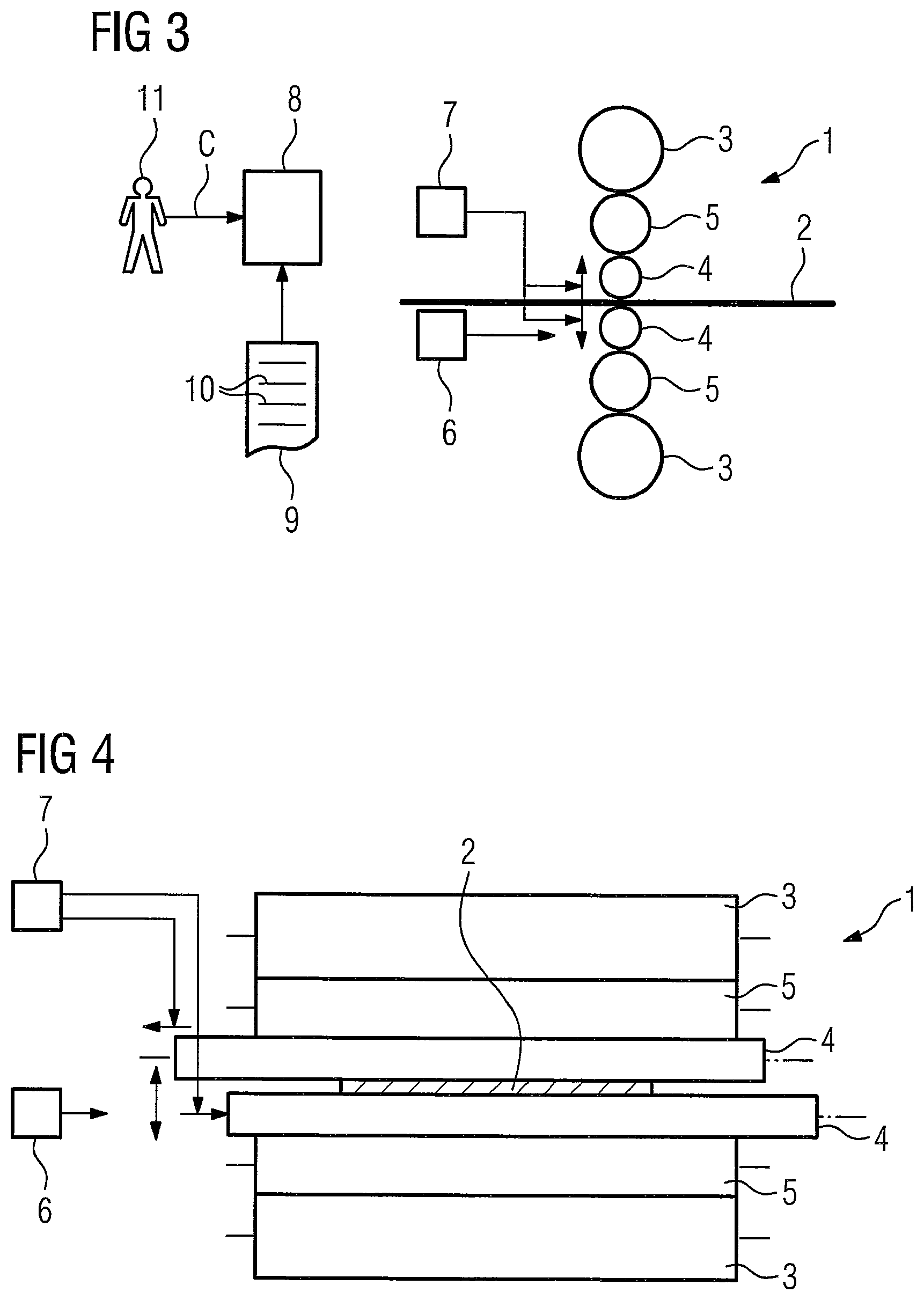
8. The method as claimed in claim 1, further comprising the control device determining a resulting edge of one of the rollers while taking into consideration a camber, a thermal crown and/or a wear of the rollers, and; and the control device blocking those axial positions (x) in which the resulting edge of one of the rollers would be positioned on a rolled product edge of the flat rolled product.
9. The method as claimed in claim 1, further comprising the control device blocking those axial positions (x) which are situated in a predetermined region around that axial position (x) in which the flat rolled product that was rolled immediately beforehand is rolled.
10. The method as claimed in claim 9, further comprising the control device blocking those axial positions (x) having spacing (a) which is situated below the minimum spacing (amin) from that axial position (x) in which the flat rolled product that was rolled immediately beforehand is rolled, for a predetermined number of flat rolled product and then cancelling the block again.
11. A control program for a control device for controlling a rolling stand, wherein the control program comprises machine code which can be processed by the control device, wherein the processing of the machine code by the control device has the effect that the control device carries out a method as claimed in claim 1.
12. A control device for a rolling stand, wherein the control device is programmed with a non-transitory control program operable to carry out a method as claimed in claim 1.
13. A rolling stand for rolling a flat rolled product, wherein the rolling stand has a pair of rollers; and the flat rolled product is situated between the two rollers; the rollers are axially displaceable in opposite directions; the rolling stand has a bending system for the rollers; the rolling stand for controlling by a control device as claimed in claim 12.
Description
CROSS-REFERENCE TO RELATED APPLICATIONS
[0001] The present application is a 35 U.S.C. .sctn..sctn. 371 national phase conversion of PCT/EP2019/053618, filed Feb. 14, 2019, the contents of which are incorporated herein by reference, which claims priority of European Patent Application No. 18160879.5 filed Mar. 9, 2018, the contents of which are incorporated by reference herein. The PCT International Application was published in the German language.
TECHNICAL FIELD
[0002] The present invention starts from a method for rolling a flat rolled product in a rolling stand, wherein; the rolling stand has at least one pair of rollers, the flat rolled product is situated between the two rollers of the pair, the rollers are axially displaceable in opposite directions, the rolling stand has a bending system for the rollers.
[0003] A control device of the rolling stand, which is for controlling the rolling gap contour, uses the bending and the axial displacement of the rollers as adjusting mechanisms. Prior to the rolling of a respective rolled product, the control device determines a respective axial position as a resulting axial position and prescribes the axial position for the rolling stand as an axial position of the rollers for rolling the next flat rolled product.
[0004] The present invention furthermore starts from a non-transitory control program for a control device for controlling a rolling stand, wherein the control program comprises machine code which can be processed by the control device, and wherein the processing of the machine code by the control device has the effect that the control device carries out such a method.
[0005] The present invention furthermore starts from a control device for a rolling stand, wherein the control device is designed such that in operation it carries out such a method, in particular is programmed with such a control program.
[0006] The present invention furthermore starts from a rolling stand for rolling a flat rolled product, the rolling stand has at least one pair of rollers, the flat rolled product is situated between the two rollers, the rollers are axially displaceable in opposite directions, the rolling stand has a bending system for the rolls, and wherein the rolling stand is controlled by such a control device.
PRIOR ART
[0007] WO 2006/000 290 A1 discloses a method of the type stated at the outset. In this method, the bending of the rollers or the displacement of the rollers are varied cyclically.
SUMMARY OF THE INVENTION
[0008] The quality of the surface and the contour of the rolled product transversely with respect to the rolling direction are decisive characteristics for a flat rolled product. As a rule, further processing steps which occur after the rolling make certain demands on the maintaining in particular of a target contour of the flat rolled product, that is the thickness profile as a function over the width of the flat rolled product.
[0009] A key influencing factor for the contour of the flat rolled product is the contour of the surfaces of the rollers of the rolling stand. This contour is composed substantially of three component parts, the roller camber of a respective roller, the thermal expansion of the respective roller and the wear of the respective roller. Particularly the wear on the rolled product edge/strip edge that is at the borders of the flat rolled product often leads to step-like patterns in the roller surface. It is therefore often necessary for measures to be taken in order to avoid such steps being imprinted into the flat rolled product.
[0010] The prior art discloses various procedures to avoid such steps being imprinted into the flat rolled product.
[0011] In the simplest case, the production is adapted. In, the course of a roller work cycle, firstly a few rolled products are rolled which become gradually wider. The rolling of these rolled products heats up the roller. Subsequently, only ever rolled products are rolled having a width that decreases gradually. This procedure is known in technical circles as the so-called coffin lid method. It has the advantage that the flat rolled products can be rolled between the worn edges of their predecessors.
[0012] A further approach consists in mechanically grinding away the worn edges during the rolling process. Such a method is known for example from WO 2006/059 667 A1.
[0013] A further approach consists in spreading the worn edge by virtue of the corresponding rollers being axially displaced during the rolling process, in particular between the rolling of rolled products which are rolled in succession. This procedure is generally known for "normal" rollers which have a substantially cylindrical roller camber. In WO 2006/000 290 A1, however, this procedure is explained for rollers which are provided with a contour which is curved in the manner of a bottleneck.
[0014] The procedure known from WO 2006/000 290 A1 already presents an advancement over a procedure, in which the displacement of the rollers for rolling a specified flat rolled product is determined, without taking into consideration the displacement of the rollers during the rolling of previously rolled flat rolled products.
[0015] However, the procedure known from WO 2006/000 290 A1 is also capable of improvement. In particular, undesired accumulation of wear can also occur at those points of the rollers which are situated in the region of the rolled product edges.
[0016] The object of the present invention consists in providing possibilities by means of which in particular the wear, as seen in the direction of the axis of rotation of the rollers, can be reliably distributed over a sufficiently large region and thus at the same time an accumulation of the wear at individual points of the rollers can be reliably counteracted.
[0017] According to the invention, a method of the type stated at the outset is configured so that, prior to the rolling of the respective rolled product, the control device determines for a plurality of axial positions of the rollers how far a predetermined target rolling gap contour can be approximated by actuating the adjusting mechanisms while taking into account technological boundary conditions. The control device classifies as permissible those axial positions in which a deviation of the resulting rolling gap contour from the target rolling gap contour lies below a predetermined limit. The control device removes blocked axial positions from the set of the axial positions classified as permissible so that at least one axial position classified as permissible still remains even after the removal of the blocked axial positions, and the control device determines one of the remaining axial positions as the resulting axial position.
[0018] The rolling stand may be a two-high stand, that is a rolling stand in which no further rollers apart from the aforementioned rollers are present. In this case, the rollers according to the invention are the working rollers of the rolling stand. As a rule, however, the rolling stand has at least two backup rollers in addition to the rollers, wherein the rollers are in each case arranged between the backup rollers and the rolled product. In this case, the rolling stand is usually a four-high stand or a six-high stand. A four-high rolling stand that has a total of four rollers arranged above one another. In this case, only backup rollers are present in addition to the rollers according to the invention.
[0019] Alternatively, the rolling stand may be a six-high stand, that is a rolling stand which, in addition to the backup rollers and the working rollers, has two intermediate rollers which are in each case arranged between one of the support rollers and one of the working rollers. In this case, the rollers according to the invention can likewise be the working rollers of the rolling stand. Alternatively, they can be the intermediate rollers. It is even possible in the case of a six-high stand that both the working rollers and the intermediate rollers are axially displaceable, so that both the working rollers and the intermediate rollers are rollers in the sense of the present invention.
[0020] It is possible that the rollers are provided with a cylindrical contour. However, full advantages are provided by the present invention when the rollers are provided with a contour which is curved in the axial direction in the manner of a bottleneck.
[0021] Within the scope of determining the permissible axial positions, the control device particularly takes into consideration technological boundary conditions of the rolling stand. Such boundary conditions are determined for example by the adjusting limits of the adjusting mechanisms and by the maximum possible adjusting speeds of the adjusting mechanisms. The adjusting limits of the adjusting mechanisms and the maximum possible adjusting speed can be technically conditioned or can be limited by corresponding stipulations of an operator.
[0022] The rolling gap contour corresponds to the thickness of the flat rolled product after rolling, positionally resolved over the strip width. The thickness of the flat rolled product is here determined over the strip width at at least 5 points, preferably at at least 10 points, and for example at 20 points or more.
[0023] The manner and way in which the control device then determines the actually used axial position from the remaining axial positions can be according to requirement.
[0024] For example, it is possible that the control device determines the resulting axial position on a stochastic basis. This very procedure particularly avoids a situation in which, for whatever reasons, specific axial positions are used disproportionately often and thus wear results in particular at those points of the further rollers at which the resulting rolled product edges are situated during the rolling of the flat rolled product.
[0025] Alternatively, it is possible that the control device assigns an evaluation to at least the remaining axial positions on the basis of an evaluation criterion and that the control device determines the resulting axial position on the basis of the evaluation. As a result, the optimal axial position, which corresponds to the evaluation, can be used in each case for rolling the respective flat rolled product. The control device can determine the evaluation in particular on the basis of technological criteria.
[0026] The blocking of axial positions can also occur according to requirement.
[0027] For example, it is possible that the control device receives a blocking command from an operator, and the control device subsequently blocks axial positions specified in the blocking command. As a result, the operator is capable of blocking specific disadvantageous axial positions, for example on the basis of superordinate technological knowledge which is not present in the control device.
[0028] As already mentioned, the rolling of flat rolled products gives rise to worn edges in the rollers. The position of these worn edges is generally known to the control device because the control device generally knows which flat rolled product has already been rolled (with which width) at which axial position of the further rollers, that is where the worn edges have arisen. In addition, it is possible according to requirement to also take into consideration the camber and the thermal crown of a respective roller. As a result, it is therefore possible that, while taking into consideration a camber, a thermal crown and/or a wear of the rollers, the control device determines a resulting edge of one of the rollers and blocks those axial positions at which the resulting edge of one of the rollers would be positioned on a rolled product edge of the flat rolled product.
[0029] Furthermore, the control device preferably blocks those axial positions which are situated in a predetermined region around that axial position in which the flat rolled product that was rolled immediately beforehand is rolled. This ensures that, during the rolling of a plurality of flat rolled products, the further rollers are positioned in a relatively large displacement region. This causes the result that the wear of the further rollers is distributed over a large region of the width of the further rollers. As a result, the service life of the further rollers is increased. In the simplest case, the predetermined region is symmetrical with respect to the axial position in which the flat rolled product that was rolled immediately beforehand is rolled. In this case, the axial position in which the flat rolled product that was rolled immediately beforehand is rolled is situated in the center of the predetermined region. However, the region can also be arranged asymmetrically.
[0030] It is possible that the control device blocks those axial positions which are situated in the predetermined region only for the flat rolled product to be rolled next in each case. Alternatively, the control device can block the corresponding axial positions for a plurality of rolled products which are rolled subsequently. Furthermore, although the control device blocks the corresponding axial positions for a number of flat rolled products, it is subsequently the case that, if the corresponding number of flat rolled products has thus been rolled, the control device cancels the block again. This applies irrespective of whether the number of flat rolled products for which the block has occurred is 1 or greater than 1.
[0031] As already mentioned, the blocking of axial positions actually classified as permissible is only performed when at least one axial position classified as permissible still remains after the blocking. As a rule, the control device blocks at least the current axial position in which the flat rolled product that was rolled immediately beforehand is rolled. However, other criteria are also possible, for example, the blocking of axial positions by the operator takes priority. The prioritization can be rigidly predetermined or be stipulated by the operator.
[0032] The object is furthermore achieved by a non-transitory control program. The processing of the control program has the effect that the control device carries out a method according to the invention.
[0033] The object is furthermore achieved by a control device. The control device is designed such that it carries out a method according to the invention. In particular, the control device can be programmed with a control program according to the invention.
[0034] The object is furthermore achieved by a rolling stand for rolling a flat rolled product, and the rolling stand is controlled by a control device according to the invention.
BRIEF DESCRIPTION OF THE DRAWINGS
[0035] The properties, features and advantages of this invention which are described above and the manner and way in which they are achieved will become better and more clearly understandable in connection with the following description of the exemplary embodiments, which are explained in more detail in conjunction with the drawings. Here, in schematically illustrated form:
[0036] FIG. 1 shows a rolling stand from the side,
[0037] FIG. 2 shows the rolling frame from FIG. 1 from the front,
[0038] FIG. 3 shows a further rolling stand from the side,
[0039] FIG. 4 shows the rolling frame from FIG. 3 from the front,
[0040] FIG. 5 shows a pair of rollers,
[0041] FIG. 6 shows a flow diagram,
[0042] FIG. 7 shows a profile of a quality value as a function of the axial position, and
[0043] FIG. 8 shows a pair of working rollers and a flat rolled product.
DESCRIPTION OF THE EMBODIMENTS
[0044] According to FIGS. 1 to 4, a flat rolled product 2 is intended to be rolled in a rolling stand 1. The rolling stand 1 has at least one pair of rollers 4, 5, between which the flat rolled product 2 passes. In principle, it is possible that only the rollers 4, 5 are present and that the rolling stand 1 is thus designed as a two-high stand. As a rule, however, a pair of backup rollers 3 is additionally present. In this case, the rollers 4, 5 are arranged between the backup rollers 3 and the flat rolled product 2. In particular, in FIGS. 1 to 4, at least working rollers 4 are present as a rule, that is rollers which in operation are in direct contact with the flat rolled product 2. If, as illustrated in FIGS. 1 and 2, only the working rollers 4 are present apart form the backup rollers 3, the rolling stand 1 is a four-high stand. If, as illustrated in FIGS. 3 and 4, intermediate rollers 5 are also present in addition to the backup rollers 3 and the working rollers 4, the rolling stand 1 is a six-high stand.
[0045] The present invention will be explained below in conjunction with embodiments in which the working rollers 4 are axially displaceable in opposite directions both for a four-high stand and for a six-high stand. However, in a six-high stand, whether alternatively to or additionally to the working rollers 4, it is also possible that the intermediate rollers 5 are axially displaceable.
[0046] Furthermore, in the invention, a distinction is made between various rolled products 2. It is possible that the various rolled products 2 are physically separated from one another, causing necessarily a longer or shorter rolling pause between the rolling of a rolled product 2 and of the following rolled product 2. However, it is also possible that the subdivision into various rolled products 2 is of a purely imaginary kind, so that a longer rolled product 2 is only conceptually subdivided into various shorter rolled products 2.
[0047] According to FIGS. 2 and 4, as already mentioned, at least one or both of the working rollers 4 are axially displaceable in opposite directions. The corresponding displacement state is referred to below as axial position x. In the context of the present invention, "axial position" is thus used not in the sense of a specific point along a roller barrel of a roller 3, 4, 5 or over the width of the flat rolled product 2, but in the sense of a specific sliding position of one working roller 4 in relation to the other working roller 4.
[0048] The working rollers 4 can be provided according to requirement with a specific contour. For example, they can be provided with a cylindrical contour. According to the illustration in FIG. 5, the working rollers 4 are each provided over their barrel length with a contour which is curved in the manner of a bottleneck. Such bottleneck-like contours are known in technical circles for example as CVC camber and as SmartCrown camber. In the loading-free state of the rolling stand 1, the contours of the working rollers 4 as a rule supplement one another in complementary fashion in a (1) axial position x. However, embodiments are also possible in which the supplementation is not complementary and/or occurs only in the loaded state of the rolling stand 1. Furthermore, the curved contours can have bevels or gradual transitions at their axial ends. However, independently of the concrete embodiment of the contours of the working rollers 4, the working rollers 4 form a parabolic rolling gap, wherein, in the case of the bottleneck-like contours, the extent of the parabolicity depends on the extent of the axial displacement of the working rollers 4.
[0049] According to FIGS. 1 to 4, the rolling stand 1 further has a bending system 6. A bending system for the rollers does not bend the rolled metal strip but the work rolls themselves in a direction perpendicular to their roll axes. It is a device which can act independent of the shifting system that shifts the rolls along their axial direction and is explained in U.S. Pat. No. 7,895,871 B2, for instance, pressure cylinders act on the chocks of the work rolls in a vertical direction. Hence, a bending system constitutes a means for modifying and controlling the resulting roll gap profile in a direction perpendicular to the transport direction of the metal strip, with the largest impact at the lateral edge portions of a metal strip. The resulting effect of the bending system must be known to the control device of the roll stand in advance such that the control device can properly actuate the bending system during the rolling process.
[0050] By means of the bending system 6, the working rollers 4 may be bent in a defined manner in a manner known per se. The bending system 6 also particularly allows the rolling gap to have a parabolic shape imparted thereto. It is therefore possible within certain limits for the effect of the axial displacement of the working rollers 4 on the one hand at the effect of the bending system 6 on the other hand to be mutually reinforcing or mutually compensating depending on the manner and extent of the respective actuation of a sliding system 7, by means of which the working rollers 4 can be displaced, and of the bending system 6. The two systems 6, 7 thus make it possible in particular for the rolling gap contour to be set.
[0051] The rolling stand 1 is controlled by a control device 8. In particular, the bending system 6 and the sliding system 7 are controlled by the control device 8. In operation, the control device 8 carries out a method which will be explained in more detail below. In particular, the control device 8 can be programmed with a non-transitory control program 9 for this purpose. In this case, the control program comprises a machine code 10 which can be processed by the control device 8. The processing of the machine code 10 causes the control device 8 to carry out the corresponding method, which in particular comprises controlling the bending system 6 and the sliding system 7.
[0052] According to FIG. 6, in a step S1, the control device 8 determines for a plurality of axial positions x of the working rollers 4 which are defined by a respective actuation of the sliding system 7 and by which respective actuation of the bending system 6 the rolling gap contour optimally approximates a predetermined target rolling gap contour. It also simultaneously determines a quality value A for the correspondence of the resulting rolling gap contour with the target rolling gap contour. The corresponding situation is illustrated in FIG. 7 by a corresponding quality value A as a function over the axial positions x. The control device 8 can determine the quality value A for example by means of a cost function. In this case, particularly at a number of supporting points over the width of the flat rolled product 2, the respective local deviation of the rolling gap contour from the target rolling gap contour is included in the cost function. The number of supporting points over the width of the flat rolled product 2 at which the control device 8 respectively determines the respective local deviation of the rolling gap contour from the target rolling gap contour is as a rule at least 5 points, and preferably at least 10 points. In many cases, the comparison is carried out even on a still considerably larger number, for example at 20, 50 or even more supporting points.
[0053] It is additionally possible for the cost function to include further variables, for example an extent and/or a speed with which the axial position x has to be adjusted, starting from a current axial positioning that is the positioning of the corresponding adjusting system 6, 7 at the time of the rolling of the flat rolled product 2 that was rolled immediately beforehand (referred to below as rolled product 2A).
[0054] The control device 8 can determine the axial positions x discretely--for example every 5 mm, every 10 mm or every 20 mm within the possible displacement range of the working rollers 4 or continuously. In the last-mentioned case, determination of the quality value A occurs as a rule only for supporting points of the axial position x. The control device 8 interpolates the quality value A between the supporting points.
[0055] The control device 8 carries out step S1 prior to the rolling of the respective flat rolled product 2 (referred to below as rolled product 2B). As a rule, the control device 8 carries out step S1 furthermore after the rolling of the rolled product 2A that was rolled immediately beforehand.
[0056] The control device 8 takes account of technological boundary conditions within the context of carrying out step S1. Such boundary conditions can consist in particular of the extent to which the bending system 6 and/or the sliding system 7 can be actuated at all, that is the maximum possible sliding stroke and the maximum possible bending stroke. Alternatively and in particular additionally, the boundary conditions can consist in the fact that, with consideration of a maximum adjusting speed for the sliding system 7, the possible range of axial positions x is limited and/or, with consideration of a maximum adjusting speed for the bending system 6, a limitation of the achievable rolling gap contour is carried out.
[0057] In a step S2, the control device 8 determines those axial positions x at which the quality value A (based substantially on the deviation of the resulting rolling gap contour from the target rolling gap contour) lies below a predetermined limit MAX. These axial positions x represent the total set of the permissible axial positions x.
[0058] In a step S3, the control device 10 then removes blocked axial positions x from the set of the permissible axial positions x.
[0059] It is possible for example for the control device 8 to receive a blocking command C from an operator 11 within step S3 (see FIGS. 1 and 3). In this case, the control device 8 blocks the axial positions x specified in the blocking command C. For example, on account of the stipulation of the operator 11, the control device 8 can block the axial position x which is supplemented by the letter A in FIG. 7.
[0060] Alternatively or additionally, it is possible that, according to the illustration in FIG. 8, the control device 8 determines at least one resulting edge 12 of the working rollers 4 and checks at which axial position x of one of the working rollers 4 the resulting edge 12 would be positioned on a rolled product edge 13 of the rolled product 2B to be rolled. In this case, according to the illustration in FIG. 7, the control device 8 for example blocks the axial position x supplemented by the letter B in FIG. 7. It is possible that, in the context of determining the resulting edge 12, the control device 8 considers only the wear of the working rollers 4. However, the control device 8 preferably determines the resulting edge 12 with consideration of the camber, the thermal crown and/or the wear of the working rollers 4.
[0061] Alternatively or additionally, it is possible that, according to the illustration in FIG. 7, the control device 8 blocks those axial positions x which are situated in a predetermined region around that axial position x at which the flat rolled product 2A that was rolled immediately beforehand, that is the flat rolled product 2A here, is rolled. For example, the control device 8 can block that axial position x whose spacing a lies below a minimum spacing amin from that axial position x at which the flat rolled product 2 that was rolled immediately beforehand is rolled. In FIG. 7, these are the axial positions x supplemented by the letter C.
[0062] In the last-mentioned case, that is the block in dependence on the predetermined region, it is possible that the block applies only to the flat rolled product 2 to be rolled next, that is the flat rolled product 2B. Alternatively, it is possible to maintain the block for a predetermined number of flat rolled products 2, for example for the flat rolled product 2B and the next two flat rolled products 2. Subsequently, however, the control device 8 automatically cancels the block again. Furthermore, the duration of the block can be a function of sign and/or magnitude of the spacing a, in particular can decrease with increasing spacing a.
[0063] The extent to which, in step S3, the control device 8 blocks axial positions x can be determined according to requirement.
[0064] However, irrespective of the extent of the blocks, the blocking is carried out only to the extent that, even after the removal of the blocked axial positions x from the set of the axial positions x classified as permissible, at least one axial position x still remains, that is both permissible and not blocked. Expressed in other terms: if only a single axial position x is permissible, this axial position x must not be blocked in step S3 since otherwise there would no longer be available a permissible axial position x for the rolling of the flat rolled product 2. If, by contrast, the number of permissible axial positions x is greater than 1, at least one (in principle permissible) axial position x is blocked in step S3. However, the blocking of axial positions x is carried out only to such a degree that even then at least one axial position x still remains permissible. Furthermore, during blocking, priority is as a rule given to blocking that axial position x at which the flat rolled product 2 that was rolled immediately beforehand that is the flat rolled product 2A here is rolled. However, other prioritizations are also possible in principle.
[0065] Furthermore, the blocking of axial positions x is not simply optional but absolutely necessary if the possibility exists at all for blocking axial positions x. Within step S3, the control device 8 thus always checks whether the number of permissible axial positions x is greater than 1. If this is the case, at least one axial position x is blocked. If, on the other hand, this is not the case, but also only then, there is no blocking of the axial position x which is permissible alone in this case.
[0066] In a step S4, the control device 8 determines the respective axial position x at which the flat rolled product 2 now to be rolled, that is the rolled product 2B according to the example, is intended to be rolled. This axial position x is referred to below as the resulting axial position x. The resulting axial position x is determined by selecting one of the permissible and at the same time not blocked axial positions x. Step S4 is also carried out prior to the rolling of the corresponding rolled product 2.
[0067] The manner and way in which the control device 8 determines the resulting axial position x can occur for example on a stochastic basis. Alternatively, the control device 8 can determine an evaluation for the axial positions x on the basis of an evaluation criterion and assign it to the axial positions x. In this case, the control device 8 determines the resulting axial position x on the basis of the evaluation. It is sufficient for the determination and assignment of the evaluation to be carried out only for the remaining axial positions x, that is the permissible and at the same time not blocked axial positions x. This is because the determination of the resulting axial position x also occurs only with consideration of these axial positions x.
[0068] The evaluation can be determined according to requirement. The control device 8 preferably determines the evaluation on the basis of technological criteria, in particular the quality value A.
[0069] In a step S5, the control device 8 finally prescribes the resulting axial position x for the rolling stand 1 as axial position x for rolling the flat rolled product 2--the rolled product 2B according to the example. The corresponding rolled product 2 is thus rolled in the rolling stand 1 with this axial position x of the working rollers 4 and with the bending system 6 in the state which corresponds thereto and which is determined within step S1.
[0070] The present invention has been explained above in such a way that the working rollers 4 are the axially displaceable rollers. However, in the case of a six-high stand, it is possible that the intermediate rollers 5 are axially displaceable. In this case, the method according to the invention is carried out with respect to the intermediate rollers 5. In the case of a six-high stand, it is even possible that both the working rollers 4 and the intermediate rollers 5 are axially displaceable. In this case, the method according to the invention can be carried out both with regard to the working rollers 4 and with regard to the intermediate rollers 5.
[0071] The present invention has many advantages. In particular, it is possible to ensure in a simple and reliable manner that the wear of the working rollers 4 and/or of the intermediate rollers 5 is spread over a large region of their axial extent, with the result that a significant worn edge cannot be formed anywhere. Where required, it is even possible for the axial position x to be determined sequentially in succession in such a way that a desired roller wear is worked towards in a very targeted manner. The various possibilities of blocking axial positions x and the various possibilities of determining the resulting axial position x from the remaining axial positions x results in a high degree of flexibility, and therefore the procedure according to the invention can be applied without further modifications in the multiplicity of rolling stands.
[0072] Although the invention has been more fully illustrated and described in detail by means of the preferred exemplary embodiment, the invention is not limited by the disclosed examples and other variants can be derived therefrom by a person skilled in the art without departing from the scope of protection of the invention.
LIST OF REFERENCE SIGNS
[0073] 1 Rolling stand
[0074] 2 Flat rolled products
[0075] 3 Backup rollers
[0076] 4 Working rollers
[0077] 5 Intermediate rollers
[0078] 6 Bending system
[0079] 7 Sliding system
[0080] 8 Control device
[0081] 9 Control program
[0082] 10 Machine code
[0083] 11 Operator
[0084] 12 Resulting edge
[0085] 13 Rolled product edge
[0086] a Spacing
[0087] amin Minimum spacing
[0088] A Quality value
[0089] MAX Limit
[0090] S1 to S5 Steps
[0091] x, xA, xB, xC Axial positions
* * * * *
D00000
D00001
D00002
D00003
D00004
XML
uspto.report is an independent third-party trademark research tool that is not affiliated, endorsed, or sponsored by the United States Patent and Trademark Office (USPTO) or any other governmental organization. The information provided by uspto.report is based on publicly available data at the time of writing and is intended for informational purposes only.
While we strive to provide accurate and up-to-date information, we do not guarantee the accuracy, completeness, reliability, or suitability of the information displayed on this site. The use of this site is at your own risk. Any reliance you place on such information is therefore strictly at your own risk.
All official trademark data, including owner information, should be verified by visiting the official USPTO website at www.uspto.gov. This site is not intended to replace professional legal advice and should not be used as a substitute for consulting with a legal professional who is knowledgeable about trademark law.