QC Wrap Pads
Truesdell; Kevin
U.S. patent application number 16/993409 was filed with the patent office on 2021-02-18 for qc wrap pads. This patent application is currently assigned to Buckingham Manufacturing Company, Inc.. The applicant listed for this patent is Buckingham Manufacturing Company, Inc.. Invention is credited to Kevin Truesdell.
| Application Number | 20210046358 16/993409 |
| Document ID | / |
| Family ID | 1000005038797 |
| Filed Date | 2021-02-18 |


View All Diagrams
| United States Patent Application | 20210046358 |
| Kind Code | A1 |
| Truesdell; Kevin | February 18, 2021 |
QC Wrap Pads
Abstract
A climber wrap pad accessory for attaching the to the upper tibia portion of the leg of the user for tree or pole climbing. The climber wrap pad includes a wrap pad body having a first end and a second end, and a buckle assembly configured to connect the first end to the second end. The buckle assembly has a first buckle connected to the first end and a complimentary second buckle connected to the second end. The climber wrap pad also includes an adjustment mechanism extending across at least a portion of the wrap pad body.
| Inventors: | Truesdell; Kevin; (Binghamton, NY) | ||||||||||
| Applicant: |
|
||||||||||
|---|---|---|---|---|---|---|---|---|---|---|---|
| Assignee: | Buckingham Manufacturing Company,
Inc. Binghamton NY |
||||||||||
| Family ID: | 1000005038797 | ||||||||||
| Appl. No.: | 16/993409 | ||||||||||
| Filed: | August 14, 2020 |
Related U.S. Patent Documents
| Application Number | Filing Date | Patent Number | ||
|---|---|---|---|---|
| 62886664 | Aug 14, 2019 | |||
| Current U.S. Class: | 1/1 |
| Current CPC Class: | A63B 27/02 20130101 |
| International Class: | A63B 27/02 20060101 A63B027/02 |
Claims
1. A climber wrap pad, comprising: a wrap pad body having a first end and a second end; a buckle assembly configured to connect the first end to the second end, the buckle assembly having a first buckle connected to the first end and a complimentary second buckle connected to the second end; and an adjustment mechanism extending across at least a portion of the wrap pad body.
2. The climber wrap pad of claim 1, wherein the wrap pad body has a main body portion extending between the first end and the second end and a side body portion extending from the main body portion.
3. The climber wrap pad of claim 2, wherein the side body portion extends at an acute angle relative to the main body portion.
4. The climber wrap pad of claim 2, further comprising an opening extending through a lower edge of the side body portion.
5. The climber wrap pad of claim 1, further comprising a gaff connected to the wrap pad body.
6. The climber wrap pad of claim 1, further comprising a hook connected to and extending from the wrap pad body.
7. The climber wrap pad of claim 1, wherein the adjustment mechanism is an adjustment strap configured to connect to a fixation device on the wrap pad body.
8. The climber wrap pad of claim 1, wherein in a connected position when the first and second buckles are connected, the adjustment mechanism is configured to increase or reduce a perimeter of the wrap pad body.
9. A climber wrap pad, comprising: a wrap pad body having a main body portion and a side body portion, the main body portion having a first end and a second end and the side body portion extending from the main body portion; a support extending through the main body portion of the wrap pad body; a loop extending from the support and through the main body portion; a connection mechanism connected to the main body portion, the connection mechanism configured to connect the first end to the second end; and an adjustment mechanism configured to extend over or through the loop.
10. The climber wrap pad of claim 9, wherein in a connected position when the first and second ends are connected via the connection mechanism, the adjustment mechanism is configured to increase or reduce a perimeter of the main body portion.
11. The climber wrap pad of claim 9, wherein the side body portion extends at an angle of 90 degrees or less relative to the main body portion.
12. The climber wrap pad of claim 9, further comprising an opening extending through a lower edge of the side body portion.
13. The climber wrap pad of claim 9, further comprising a gaff connected to the side body portion.
14. The climber wrap pad of claim 13, wherein a hook extends from the side body portion and the gaff extends from the hook.
15. The climber wrap pad of claim 14, wherein the hook curves toward the wrap pad body and the gaff extends away from the wrap pad body.
16. The climber wrap pad of claim 9, wherein the adjustment mechanism is an adjustment strap configured to connect to a fixation device on the wrap pad body.
17. The climber wrap pad of claim 9, further comprising a hook and loop fastener patch on the wrap pad body configured to attach to the adjustment mechanism.
18. The climber wrap pad of claim 9, wherein the connection mechanism is connected to the main body portion via strap.
19. The climber wrap pad of claim 18, wherein the strap comprises an adjustability section.
20. The climber wrap pad of claim 19, wherein the adjustability section is a clip.
Description
CROSS-REFERENCE TO RELATED APPLICATION
[0001] The present application claims priority to and the benefit of U.S. Provisional Patent Application No. 62/886,664, filed on Aug. 14, 2019 and entitled "QC Wrap Pads," the entirety of which is incorporated herein by reference.
BACKGROUND OF THE INVENTION
1. Field of the Invention
[0002] The present invention is directed generally to a climber with a gaff and, more particularly, to a tree or pole climbing accessory for attaching the climber to the upper tibia portion of the leg of the user.
2. Description of Related Art
[0003] Climbing harnesses for lineman and lumberjacks comprise "climbers" of fairly standard construction. One such harness is shown in U.S. Pat. No. 672,755, issued on Apr. 23, 1901. These climbers feature an elongated, rigid metal bar, referred to as a leg iron, that extends under the shank of the shoe or boot of the lineman. On the lower end of the leg iron is a spike or spur for insertion into the pole or tree. The upper end of the leg iron attaches to the upper tibia portion of the lineman's leg by means of a strap which fits into a metal loop in the leg iron. The strap wraps around the tibia portion of the leg, and is secured by a buckle.
[0004] It has been observed that the strap tends to cause discomfort to the linemen, particularly after a long period of standing in the harness. The strap, which is usually a thin strip of leather or nylon, tends to twist and bite into the leg. Blood circulation is often impaired, and the leg iron shank has been known to shift and cause injury. In order to relieve the discomfort caused by the strap, small padded cushions have been designed to shield the contact area between the inner shank portion of the leg and the strap. One such shielding pad is illustrated in U.S. Pat. No. 1,727,237, issued Sep. 3, 1929. In modern times the padded cushions have been designed to lend greater support to the leg, by featuring an increased wrap-around area. One such improved wrap-around pad is depicted in the patent to Hobbs; U.S. Pat. No. 4,530,420, issued Jul. 23, 1985. The pad of the above-identified invention is highly cushioned and extends half-way around the leg, thus providing an increased contact area against chafing and twisting of the strap.
[0005] While the aforementioned climber and pad are effective, there are some drawbacks. The traditional climbers and pads require the user to wrap the strap around his or her leg and either feed the strap through a buckle or wrap it back onto itself with a hook and loop fastener. Due to the strap and buckle or fastener methods for securing the strap, multiple readjustments to ensure the proper fit and tightness take time and can be difficult to execute. Therefore, there is a need for a climber with an easy-to-use adjustment mechanism.
[0006] Description of the Related Art Section Disclaimer: To the extent that specific patents/publications/products are discussed above in this Description of the Related Art Section or elsewhere in this disclosure, these discussions should not be taken as an admission that the discussed patents/publications/products are prior art for patent law purposes. For example, some or all of the discussed patents/publications/products may not be sufficiently early in time, may not reflect subject matter developed early enough in time and/or may not be sufficiently enabling so as to amount to prior art for patent law purposes. To the extent that specific patents/publications/products are discussed above in this Description of the Related Art Section and/or throughout the application, the descriptions/disclosures of which are all hereby incorporated by reference into this document in their respective entirety(ies).
BRIEF SUMMARY OF THE INVENTION
[0007] It is therefore a principal object and advantage of the present invention to provide a climber with an easy-to-use adjustment mechanism. Embodiments of the present invention are directed to climber wrap pad. According to one aspect, the climber wrap pad includes a wrap pad body having a first end and a second end, and a buckle assembly configured to connect the first end to the second end. The buckle assembly has a first buckle connected to the first end and a complimentary second buckle connected to the second end. The climber wrap pad also includes an adjustment mechanism extending across at least a portion of the wrap pad body.
[0008] According to another aspect, the climber wrap pad includes a wrap pad body having a main body portion and a side body portion. The main body portion has a first end and a second end. The side body portion extends from the main body portion. A support extends through the main body portion of the wrap pad body. A loop extends from the support and through the main body portion. The climber wrap pad also includes a connection mechanism and an adjustment mechanism. The connection mechanism is connected to the main body portion and is configured to connect the first end to the second end. The adjustment mechanism is configured to extend over or through the loop.
[0009] These and other aspects of the invention will be apparent from and elucidated with reference to the embodiment(s) described hereinafter.
BRIEF DESCRIPTION OF THE SEVERAL VIEWS OF THE DRAWING(S)
[0010] The present invention will be more fully understood and appreciated by reading the following Detailed Description in conjunction with the accompanying drawings. The accompanying drawings illustrate only typical embodiments of the disclosed subject matter and are therefore not to be considered limiting of its scope, for the disclosed subject matter may admit to other equally effective embodiments. Reference is now made briefly to the accompanying drawings, in which:
[0011] FIG. 1 is a front view schematic representation of a climber wrap pad in a planar position, according to an embodiment;
[0012] FIG. 2 is a perspective view schematic representation of a climber wrap pad, according to an embodiment;
[0013] FIG. 3 is a pictorial, side view of a climber wrap pad, according to an embodiment;
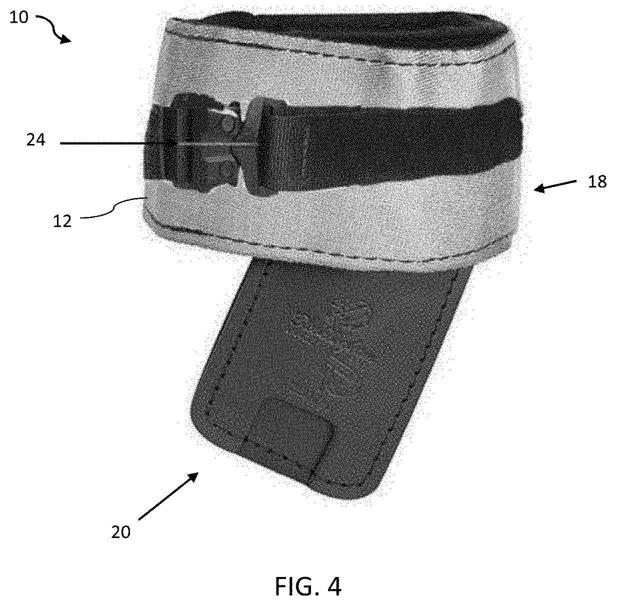
[0014] FIG. 4 is a pictorial, side view of a climber wrap pad with a connection mechanism, according to an embodiment;
[0015] FIG. 5 is a pictorial, close-up view of a connection mechanism of the climber wrap pad, according to an embodiment;
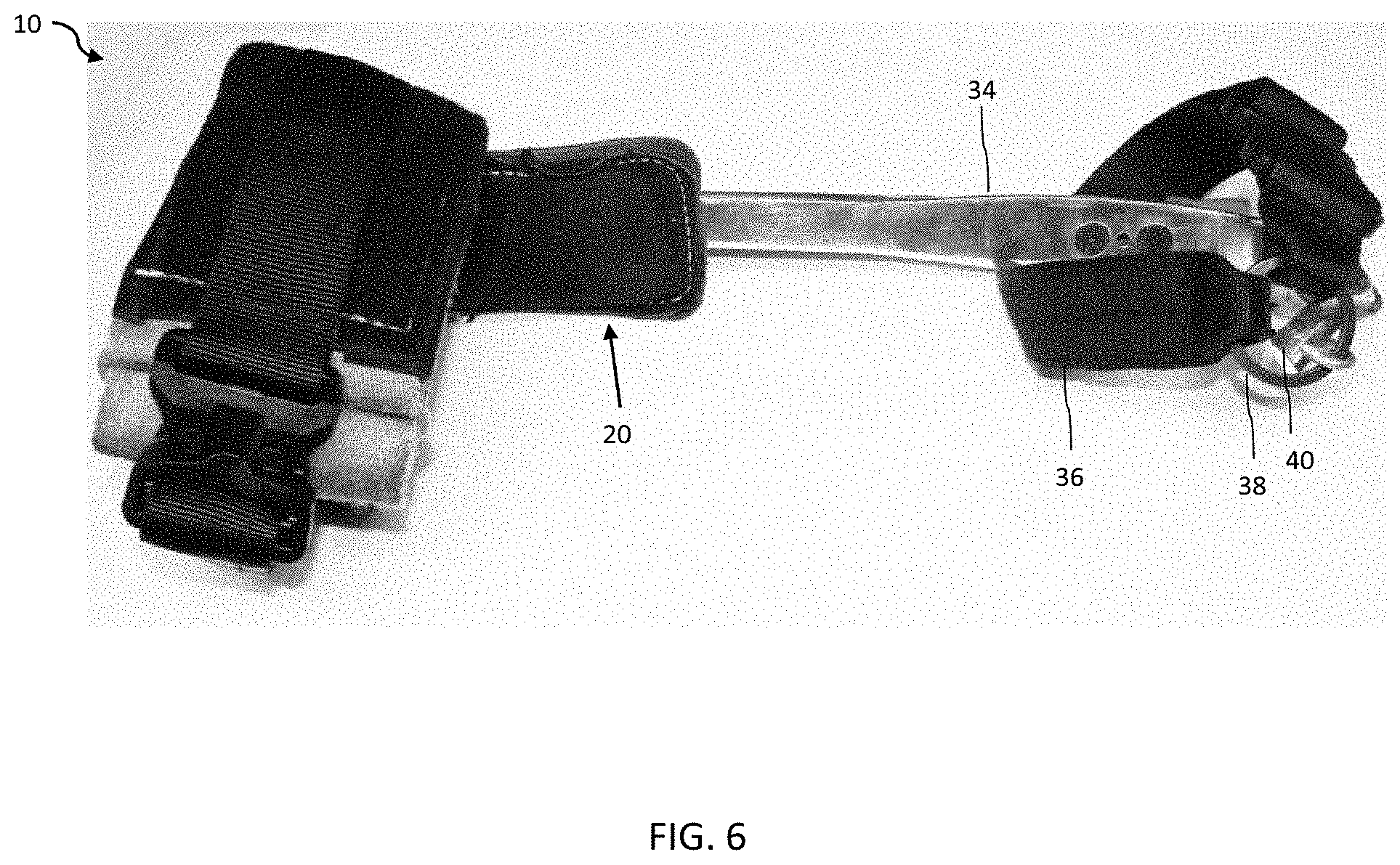
[0016] FIG. 6 is a pictorial, perspective view of a climber wrap pad attached to a hook and accessory, according to an embodiment;
[0017] FIG. 7 is a pictorial, front view of a climber wrap pad, according to an alternative embodiment;
[0018] FIG. 8 is a pictorial, perspective view of a support of a climber wrap pad, according to yet another embodiment;
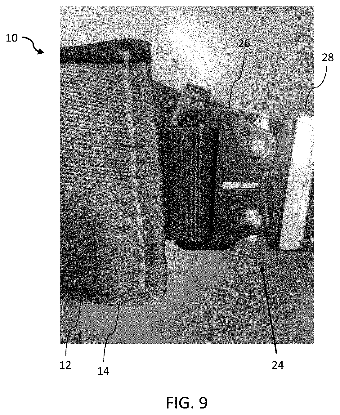
[0019] FIG. 9 is a pictorial, close-up view of a connection mechanism of the climber wrap pad, according to an embodiment;
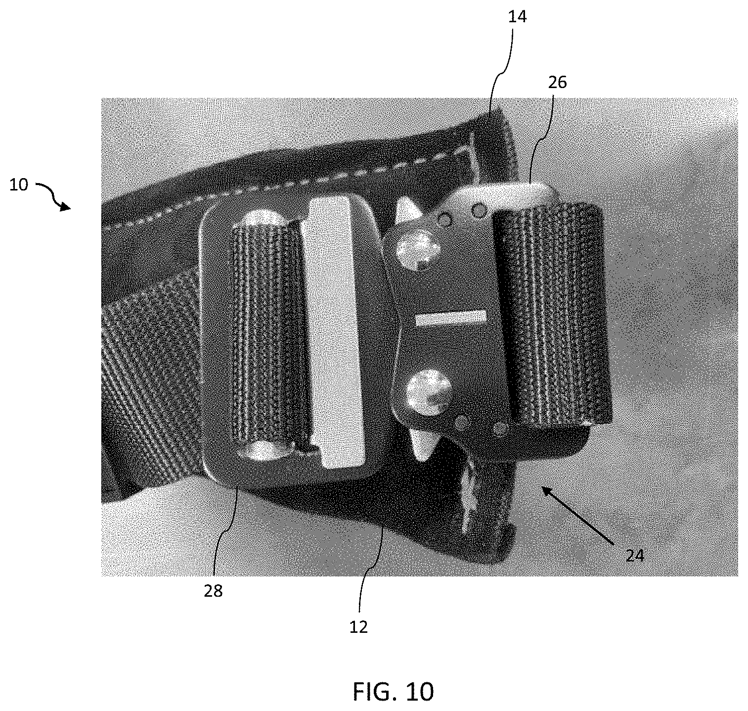
[0020] FIG. 10 is another pictorial, close-up view of a connection mechanism of the climber wrap pad, according to an embodiment;
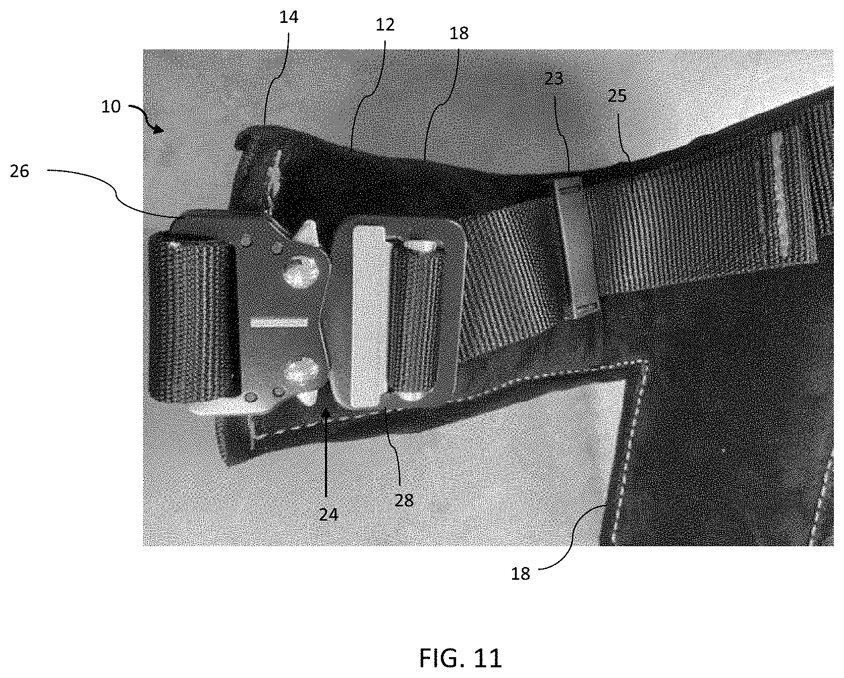
[0021] FIG. 11 is yet another pictorial, close-up view of a connection mechanism and an adjustability section of the climber wrap pad, according to an embodiment;
[0022] FIG. 12 is a pictorial, back view of climber wrap pads, according to an embodiment;
[0023] FIG. 13 is a pictorial, close-up view of a side body portion of the climber wrap pad, according to an embodiment;
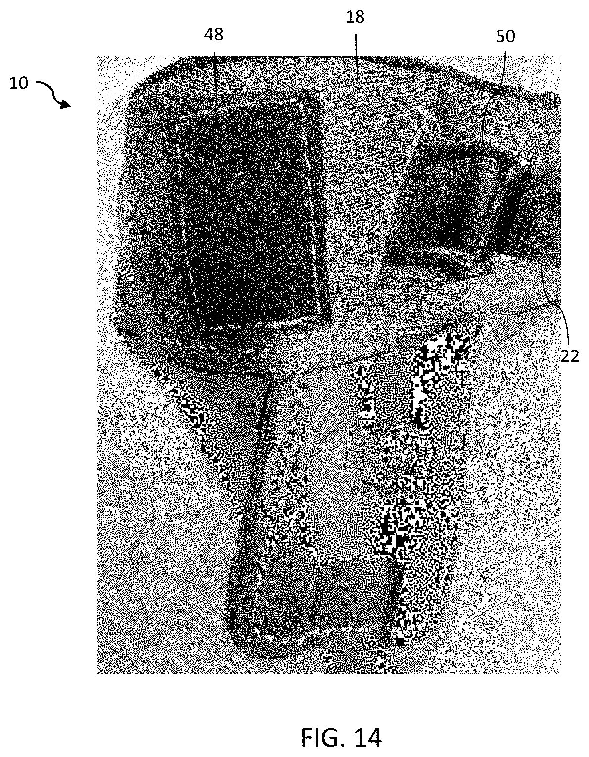
[0024] FIG. 14 is a pictorial, close-up view of an adjustment mechanism of the climber wrap pad, according to an embodiment;
[0025] FIG. 15 is a pictorial, close-up view of an adjustment mechanism of the climber wrap pad, according to an alternative embodiment;
[0026] FIG. 16 is another pictorial, close-up view of an adjustment mechanism of the climber wrap pad, according to an alternative embodiment; and
[0027] FIG. 17 is a pictorial, side view of climber wrap pads, according to an alternative embodiment.
DETAILED DESCRIPTION OF THE INVENTION
[0028] Aspects of the present invention and certain features, advantages, and details thereof, are explained more fully below with reference to the non-limiting examples illustrated in the accompanying drawings. Descriptions of well-known structures are omitted so as not to unnecessarily obscure the invention in detail. It should be understood, however, that the detailed description and the specific non-limiting examples, while indicating aspects of the invention, are given by way of illustration only, and are not by way of limitation. Various substitutions, modifications, additions, and/or arrangements, within the spirit and/or scope of the underlying inventive concepts will be apparent to those skilled in the art from this disclosure.
[0029] Referring now to the figures, wherein like reference numerals refer to like parts throughout, FIG. 1 shows a front view schematic representation of a climber wrap pad 10 in a planar position, according to an embodiment. The purpose of the climber wrap pad 10 is to provide an easy-to-use one-step connection and/or adjustment. The climber wrap pad 10 comprises a wrap pad body 12 extending between a first end 14 and a second end 16. The wrap pad body 12 is composed of a fabric or foam. In the depicted embodiment, the wrap pad body 12 is substantially rectangular.
[0030] Specifically, in FIG. 1, the wrap pad body 12 has a main body portion 18 and a side body portion 20. The side body portion 20 extends from the main body portion 18. The main body portion 18 extends along a central, first axis and the side body portion 20 extends along a second axis. The second axis is at an angle relative to the first axis. In the depicted embodiment, the second axis extends from the first axis at an acute angle. The wrap pad body 12 is sized and configured to extend around the circumference or perimeter of the upper tibia portion of the leg of the user.
[0031] Still referring to FIG. 1, the climber wrap pad 10 further comprises an adjustment mechanism 22 on the main body portion 18. The adjustment mechanism 22 is used to alter the circumference or perimeter of the main body portion 18 around the upper tibia portion of the leg of the user. The climber wrap pad 10 also has a connection mechanism 24. The connection mechanism 24 is used to connect the first end 14 of the wrap pad body 12 to the second end 16 of the wrap pad body 12.
[0032] Turning now to FIG. 2, there is shown a perspective view schematic representation of a climber wrap pad 10, according to an embodiment. In the depicted embodiment, the connection mechanism 24 is a buckle assembly. The buckle assembly 24 comprises a first buckle 26 connected to the first end 14 of the wrap pad body 12 and a second buckle 28 connected to the second end 16 of the wrap pad body 12. In an embodiment, the first buckle 26 is a female buckle (connector) and the second buckle 28 is a male buckle (connector).
[0033] Still referring to FIG. 2, the adjustment mechanism 22 is an adjustment strap. The adjustment strap 22 extends across the main body portion 18 of the wrap pad body 12. Specifically, the adjustment strap 22 extends along the central, first axis of the main body portion 18. In the depicted embodiment, the adjustment strap 22 comprises a fixation device 30. After the user adjusts the size of the circumference or perimeter of the main body portion 18 by tensioning or loosening the adjustment strap 22, the user engages the fixation device 30 with the adjustment strap 22, fixing the adjustment strap 22 at the desired size of the circumference or perimeter of the main body portion 18.
[0034] Also in the embodiment of the climber wrap pad 10 in FIG. 2, the side body portion 20 extends substantially perpendicular to the main body portion 18. In other words, the second axis extending through the side body portion 20 is substantially perpendicular to the central, first axis extending through the main body portion 18. In the depicted embodiment, the side body portion 20 is a separate piece of material that is connected to the main body portion 18. However, it is contemplated that in some embodiments, the side body portion 20 and the main body portion 18 are one continuous piece of material.
[0035] In FIG. 2, the side body portion 20 has a gaff 32 connected to and extending therefrom. The gaff 32 can be replaced with or combined with any other hook, spear, spar, or sharp feature. In FIG. 2, the side body portion 20 is connected to a hook 34, which has a gaff 32 extending therefrom. In the depicted embodiment, the hook 34 curves toward the climber wrap pad 10 and the gaff 32 extends in an opposing direction, outwardly from the climber wrap pad 10.
[0036] Referring now to FIGS. 3-6, there are shown various pictorial views of the climber wrap pad 10, according to another embodiment. In FIG. 3, the climber wrap pad 10 is shown with a fabric (e.g., nylon) main body portion 18 with a leather side body portion 20 extending therefrom. In the depicted embodiment, the side body portion 20 and second axis extends at an acute angle from the main body portion 18 and central, first axis. In FIG. 4, the climber wrap pad 10 of FIG. 3 has a connection mechanism 24 that is a buckle assembly (as described with reference to FIGS. 1-2 above). The buckle assembly 24 is shown in a connected position in FIG. 4. A close-up view of the buckle assembly 24 in the connected position is shown in FIG. 5.
[0037] The embodiment of the climber wrap pad 10 shown in FIG. 6 has a hook 34 extending from the side body portion 20. The hook 34 has an accessory 36 connected thereto. In the depicted embodiment, the accessory 36 is a strap. Specifically, the strap 36 is connected to a ring 38, which is connected to a free end 40 of the hook 34. The purpose of the strap 36 is to secure around an ankle or shin area of the user.
[0038] Turning briefly to FIG. 7, there is shown a front view of the climber wrap pad 10, according to an alternative embodiment. The climber wrap pad 10 in FIG. 7 has the main body portion 18 of the wrap pad body 12 but lacks the side body portion 20 extending therefrom. In the depicted embodiment, the main body portion 18 is composed of leather material. The connection mechanism 24 is a buckle assembly (as described with reference to FIGS. 1-2 above). The buckle assembly 24 is shown in the connected position.
[0039] Referring now to FIGS. 8-17, there are shown various pictorial views of a climber wrap pad 10, according to yet another embodiment. FIG. 8 shows a pictorial, perspective view of a support 42 of the climber wrap pad 10. In the embodiment shown in FIGS. 8-17, the support 42 extends within the wrap pad body 12. The support 42 is composed of hard material, such as hard plastic. The wrap pad body 12 is composed of fabric material and extends around the support 42. Thus, the support 42 provides structure to the wrap pad body 12 (FIG. 12).
[0040] FIGS. 9-11 show pictorial close-up views of the connection mechanism 24 of the climber wrap pad 10. In the depicted embodiment, the connection mechanism 24 is a buckle assembly. The buckle assembly 24 comprises a first buckle 26 connected to the first end 14 of the wrap pad body 12 and a second buckle 28 connected to the second end 16 of the wrap pad body 12. In an embodiment, the first buckle 26 is a female buckle and the second buckle 28 is a male buckle. The buckle assembly 24 is shown in the connected configuration in FIGS. 9-11.
[0041] The embodiment of the climber wrap pad 10 shown in FIG. 11 has an adjustability section 23 connected to or extending from the connection mechanism 24. The adjustability section 23 is a clip. In the depicted embodiment, the connection mechanism 24 is attached to the wrap pad body 12 via a strap 25.
[0042] In FIG. 11, the strap 25 is connected to or extends from the second buckle 28 (e.g., male buckle). Therefore, after the user places the connection mechanism 24 into the connected position around his or her leg, the user can adjust how tight the main body portion 18 is around the leg by tensioning or loosening the strap 25 via the adjustability section 23 (e.g., clip). As shown in FIG. 12, the adjustment mechanism 22 extends from the first end 14 of the wrap pad body 12 to the second end 16 of the wrap pad body 12. In the connected position, the strap 25 across the main body portion 18 of the wrap pad body 12 from the first end 14 to the second end 16. Specifically, the strap 25 extends along the central, first axis of the main body portion 18.
[0043] Turing now to FIG. 13, there is shown a pictorial, close-up view of the side body portion 20 of the climber wrap pad 10, according to an embodiment. The side body portion 20 is composed of a leather material. The side body portion 20 comprises an opening 44 in its lower edge 46. In FIG. 13, the opening 44 is rectangular; however it can have any suitable geometry. The opening 44 is sized and configured to receive a hook, spear, spar, or other sharp feature.
[0044] Referring now to FIGS. 14-17, there are shown various pictorial views of an adjustment mechanism 22 of the climber wrap pad 10 of FIGS. 8-13. The adjustment mechanism 22 in FIGS. 14-17 is an adjustment strap. The adjustment strap 22 is configured to connect to a hook and loop fastener patch 48, as shown in FIG. 15. The patch 48 is on the main body portion 18 of the climber wrap pad 10 and is spaced from the adjustment strap 22. The adjustment strap 22 has complimentary hook and loop fasteners (not shown) to connect to the hook and loop fastener patch 48, as shown in FIGS. 16-17.
[0045] Turning back to FIGS. 14-15, the adjustment mechanism 22 may additionally include a loop 50. As shown in FIGS. 14-15, the loop 50 is part of a U-shaped plate connected to the support 42 (FIG. 8) of the main body portion 18 between the adjustment strap 22 and the hook and loop fastener patch 48. The loop 50 extends through the main body portion 18. The user has the option to secure the complimentary hook and loop fasteners (not shown) on the adjustment strap 22 to the hook and loop fastener patch 48 (FIGS. 16-17) or feed the adjustment strap 22 through the loop 50 and attach it back onto itself via a fixation device 30 on the adjustment strap 22 (FIG. 16). Thus, there are numerous methods of adjusting how tight or loose the wrap pad body 12 is around the leg of the user and securing it at the appropriate tightness.
[0046] In use, the user can estimate the proper fit of the climber wrap pad 10 by securing the adjustment strap 22 at the appropriate tightness. Then, the user can secure the climber wrap pad 10 around his or her leg by bringing the opposing ends 14, 16 of the climber wrap pad 10 together and connecting the male buckle 28 to the female buckle 26. If the fit needs to be readjusted, the user can simply move the adjustment strap 22 to the appropriate tightness without unbuckling the connection mechanism 24 or removing the climber wrap pad 10 from his or her leg. Traditional adjustment mechanisms tend to loosen over time, but the climber wrap pad 10, with the male and female buckles 28, 26 separated from the adjustment strap 22, resists stretching from wear, making it easier to put on.
[0047] While embodiments of the present invention has been particularly shown and described with reference to certain exemplary embodiments, it will be understood by one skilled in the art that various changes in detail may be effected therein without departing from the spirit and scope of the invention as defined by claims that can be supported by the written description and drawings. Further, where exemplary embodiments are described with reference to a certain number of elements it will be understood that the exemplary embodiments can be practiced utilizing either less than or more than the certain number of elements.
[0048] Aspects of the present invention and certain features, advantages, and details thereof, are explained more fully below with reference to the non-limiting examples illustrated in the accompanying drawings. Descriptions of well-known structures are omitted so as not to unnecessarily obscure the invention in detail. It should be understood, however, that the detailed description and the specific non-limiting examples, while indicating aspects of the invention, are given by way of illustration only, and are not by way of limitation. Various substitutions, modifications, additions, and/or arrangements, within the spirit and/or scope of the underlying inventive concepts will be apparent to those skilled in the art from this disclosure.
* * * * *
D00000
D00001
D00002
D00003
D00004
D00005
D00006
D00007
D00008
D00009
D00010
D00011
D00012

D00013

D00014
D00015

D00016

D00017

XML
uspto.report is an independent third-party trademark research tool that is not affiliated, endorsed, or sponsored by the United States Patent and Trademark Office (USPTO) or any other governmental organization. The information provided by uspto.report is based on publicly available data at the time of writing and is intended for informational purposes only.
While we strive to provide accurate and up-to-date information, we do not guarantee the accuracy, completeness, reliability, or suitability of the information displayed on this site. The use of this site is at your own risk. Any reliance you place on such information is therefore strictly at your own risk.
All official trademark data, including owner information, should be verified by visiting the official USPTO website at www.uspto.gov. This site is not intended to replace professional legal advice and should not be used as a substitute for consulting with a legal professional who is knowledgeable about trademark law.