A Swing Training Practice Club
ARNOLD; Brett ; et al.
U.S. patent application number 16/967081 was filed with the patent office on 2021-02-18 for a swing training practice club. The applicant listed for this patent is Arnolds Innovations Pty Ltd. Invention is credited to Craig ANDREWS, Brett ARNOLD, Rohaan TANEJA, Pavel ZOCEK.
| Application Number | 20210046348 16/967081 |
| Document ID | / |
| Family ID | 1000005191701 |
| Filed Date | 2021-02-18 |
View All Diagrams
| United States Patent Application | 20210046348 |
| Kind Code | A1 |
| ARNOLD; Brett ; et al. | February 18, 2021 |
A Swing Training Practice Club
Abstract
A practice club for practicing a sport is described, the practice club including a club shaft; an extendible bump assembly including a stopper movable between a rest position in which it rests against a mounting stop, and an extended position in which the stopper extends a selected distance from the stop. There is also described a sports club or bat with a tension indicator disposed on a shaft of the practice club or bat to indicate tension of an inextensible stringer or resilient element in or on the practice club or bat.
| Inventors: | ARNOLD; Brett; (Dolans Bay, New South Wales, AU) ; ANDREWS; Craig; (Kirribilli, New South Wales, AU) ; ZOCEK; Pavel; (Kirribilli, New South Wales, AU) ; TANEJA; Rohaan; (Kirribilli, New South Wales, AU) | ||||||||||
| Applicant: |
|
||||||||||
|---|---|---|---|---|---|---|---|---|---|---|---|
| Family ID: | 1000005191701 | ||||||||||
| Appl. No.: | 16/967081 | ||||||||||
| Filed: | February 4, 2019 | ||||||||||
| PCT Filed: | February 4, 2019 | ||||||||||
| PCT NO: | PCT/AU2019/050080 | ||||||||||
| 371 Date: | August 3, 2020 |
| Current U.S. Class: | 1/1 |
| Current CPC Class: | A63B 69/3632 20130101; A63B 69/0002 20130101; A63B 2069/0008 20130101; A63B 69/0015 20130101; A63B 15/005 20130101; A63B 2102/32 20151001; A63B 2220/833 20130101 |
| International Class: | A63B 15/00 20060101 A63B015/00; A63B 69/00 20060101 A63B069/00; A63B 69/36 20060101 A63B069/36 |
Foreign Application Data
| Date | Code | Application Number |
|---|---|---|
| Feb 2, 2018 | AU | 2018900327 |
| Aug 8, 2018 | AU | 2018902900 |
| Nov 2, 2018 | AU | 2018904173 |
Claims
1. A practice club or bat for practicing a sport, the practice club including: a club shaft including a handle end and a distal end; an extendable head assembly including a resilient extensible connector, a tensioner for to place the resilient extensible connector under a selected among of tension, and a head, the head movable in use between a rest position in which it rests against a mounting stop at the distal end, and an extended position during a time the club is being swung, in which the head extends a selected distance from the distal end mounting stop.
2. The practice club in accordance with claim 1 wherein the length of the connector is variable to vary the tension of the connector.
3. The practice club in accordance with claim 1 wherein the mass of the head is variable to vary the dynamic of the swing.
4. The practice club in accordance with claim 1 wherein the connector includes one or more inextensible cord portions.
5. The practice club in accordance with claim 1 further including a tension indicator disposed on the club shaft.
6. The practice club in accordance with claim 5 wherein the tension indicator includes a window on a club shaft wall to provide a view of the connector.
7. The practice club in accordance with claim 5 wherein the connector includes markings thereon to indicate tension to a player.
8. (canceled)
9. The practice club in accordance with claim 2 wherein the tension adjuster tensioner is in the form of a rotatable actuator which is configured to draw the resilient cord around an axle.
10. The practice club in accordance with claim 2 wherein the tension adjuster tensioner is in the form of a rotatable actuator which draws a lace around an axle so as to extend or retract the connector.
11. (canceled)
12. The practice club in accordance with claim 2 wherein the tensioner includes a clutch to provide release and engagement positions for the axle relative to the stopper.
13. The practice club in accordance with claim 2 wherein the tensioner includes an axle accessible from both ends of the stopper.
14. The practice club in accordance with claim 2 wherein the tensioner includes an axle that is configured to be depressed to release the clutch.
15. The practice club in accordance with claim 2 wherein the tensioner includes an axle that extends transversely to the club shaft.
16. The practice club in accordance with claim 2 wherein the tensioner includes a clutch that includes a ratchet to control the release of the tension in the cord.
17. The practice club in accordance with claim 2 wherein the tensioner may include a biasing element to provide fail safe locking position for the clutch.
18. The practice dub in accordance with claim 1 wherein a mounting stop is provided, in the form of flange or a cup for receiving the head, and the mounting stop is a shape cooperating with the head or stopper shape to receive the stopper on a broad surface area.
19. (canceled)
20. The practice club in accordance with claim 1 including a joint to tilt the mounting stop to an angle transverse to the club shaft.
21. The practice club in accordance with claim 2 wherein the mass of the stopper is varied by providing mass receivers on or in the stopper.
22. The practice dub in accordance with claim 21 wherein the stopper is hollow and includes an access port to receive weights inside.
23. A sports club or bat with a tension indicator disposed on a shaft of the practice club or bat to indicate tension of an inextensible stringer or resilient element in or on the practice club or bat.
24-28. (canceled)
Description
[0001] This application is a US 371 Application from PCT/AU2019/050080 filed Feb. 4, 2019, which claims priority from AU2018900327 filed on 2 Feb. 2018, AU2018902900 filed on 8 Aug. 2018 and AU2018904173 filed on 2 Nov. 2018, the entire contents of which are incorporated herein by referring to them in this statement.
TECHNICAL FIELD
[0002] The present technology relates generally to a practice club and methods for practicing a club swing, The present technology finds particularly effective application in golf, but it may be applied to baseball, cricket and other sports where clubs and bats are used.
BACKGROUND
[0003] Club sports can be challenging.
[0004] Golf, in particular, is very difficult to master. Optimally and accurately swinging a club can be very difficult, because so many variables come into play. It is said that there are more than 90 variables including ball position, grip, hand position, stance, hand to lower arm angle, spine angle, club length. Many of these variables need to be deployed in the right sequence to obtain a good swing.
[0005] One important swing variable is downswing. A particular problem often experienced by novice golf players is that the hands and arms are moved too quickly during the downswing with the consequence that the club moves in advance of its desired position relative to the hips. A particular feature of many professional golfers is that their swing incorporates a desirable "lag" of the club head behind the golfer's hands during the downswing. The swing of the late Ben Hogan is thought to have been a particularly good example in this connection.
[0006] A particular advantage of the devices of the embodiment of the present technology is that they facilitate novice players to experience a swing which incorporates the above mentioned desirable lag of the club head, although the devices to be described are not solely restricted to this aspect of the swing.
[0007] Another important swing variable is club follow through, which is the trajectory and speed of club travel after the club head hits the ball. Clearly, the follow through is at least partially dependent on the trajectory and speed of the down-swing.
[0008] it is difficult to improve the down-swing and follow through with a normal club without going to the trouble of physically driving to a range, or having complex machinery, or losing a lot of balls, or other time-intensive and unhelpful distractions, in any event, it is not clear whether the lessons learnt with known machines or even on a driving range can be directly transferred to the course.
[0009] The genesis of the present invention is a desire to provide a device which provides an experience to a player of what a good swing should feel like. One intention is that repeated simulated good swings enables a muscle memory within the brain and body of the player to be developed. One aim is that having developed the appropriate muscle memory, the player is then able to apply it when playing with their own clubs or bats and thereby improve their game.
[0010] The present inventor seeks to provide a practice club which facilitates swing training, and/or which at least provides a useful alternative to known alternatives.
SUMMARY
[0011] Broadly, the present technology provides a practice club which provides feedback on a user's swing.
[0012] Broadly, the present technology provides a practice club which in use provides haptic feedback to a user during the user's swing.
[0013] Broadly, the present technology provides a practice club which during a swing provides a tactile sensation which can be felt through hands when in a grip position on a club shaft. On the downswing, and/or the follow-through, the dynamics of a swing of an actual swing are transmitted into the shaft of the practice club. It may be that a ball is not available or other conditions are not able to be met to hit a ball and this may be a convenient way to practice, or ij may be useful to instill the right technique by accentuating certain dynamic conditions on the practice club. The return bump that may be felt could be a snap, or audible noise to feedback to the user some relevant information about the velocity profile of a user's swing.
[0014] Broadly the present technology provides a practice club which provides tunable haptic feedback to the user on the velocity profile of the swing trajectory during a swing.
[0015] The arrangement may be that the practice club has a resiliently held mass element on a distal end thereof. In use the user swings the practice club with the aim of increasing the centripetal (or in lay terms centrifugal) force on the resiliently-held mass element so it is driven away from the distal end of the club during a down swing. The user can feel that movement away from the distal end of the club. The user may also feel the angular location of the resiliently-held mass leaving the mounting stop. Then, if the swing is good, the resiliently-held mass snaps back into a mounting stop at a selected portion of the follow-through. Players may aim to have the resiliently-held mass hit the distal end of the club during the follow through by aiming to slow the club down in a selected angular range of the follow through. The user may use the feedback to refine the swing so that a particular angle from vertical (during the follow through) is selected for a haptic bump. In poor swings, ij may even be that the return occurs during the downswing, which of course is undesirable and the user may immediately note the angle of the return by the feel.
[0016] Again, or alternatively, for clarity, the arrangement is such that an extensible element in the club is caused to extend away from a mounting stop during the down swing or follow through, and return to the mounting stop, preferably during the follow through. The user is caused to feel a haptic bump across or along the shaft at a point in the swing where the club is caused to slow down. The position of the bump provides feedback on the swing.
[0017] In accordance with one aspect of the present invention there is provided a practice club for practicing a club sport, the practice club including: [0018] a. a club shaft; [0019] b. a resiliently-mounted mass assembly including a stopper movable between a rest position in which it rests against a mounting stop, and an extended position, under centrifugal load, in which the stopper extends a selected distance from the stop.
[0020] In accordance with another aspect of the present invention there is provided a practice club or bat for practicing a sport, the practice club including: [0021] a. a club shaft including a handle end and a distal end; [0022] b. an extendible head assembly including a resilient extensible connector, a tensioner for to place the resilient extensible connector under a selected amount of tension, and a head,
[0023] c. the head movable in use between a rest position in which it rests against a mounting stop at the distal end, and an extended position during a time the club is being swung, in which the head extends a selected distance from the distal end mounting stop.
[0024] In accordance with another aspect of the present invention there is provided a method for practicing a golf swing, the method including the steps of:
[0025] a. swinging a practice club through the air, such that an extendible stopper mounted on or in the practice club extends from a rest position against a mounting stop on or in the club.
[0026] The method may further include the step of slowing the club to cause the stopper to return to the mounting stop with a bump.
[0027] In accordance with still another aspect of the present invention there is provided a sports club or bat with a tension indicator disposed on a shaft of the practice club or bat to indicate tension of a resilient element in or on the practice club or bat.
[0028] The resilient element may stiffen the club or bat to stiffen the club or bat shaft.
[0029] The resilient element may facilitate release of a club head or bump stopper during a swing.
[0030] In accordance with yet another aspect of the present technology there is provided a sports club or bat with a tensioning device for a flexible element.
[0031] In one embodiment the tensioning device may be a batten or a stringer element so as to provide an increase in stiffness along one or more portions of the club or bat. Although various embodiments of the technology are directed to a practice club, the tension element may be used in a golf club. The batten may be fairly inextensible such that an increase in tension may only move the tensioning indicator by 0.5 mm or 10 mm or 1.5, 2, 2.5, 3 mm, 3.5, 4 or 4.5 or 5 mm or thereabouts. There may be adjustment of the cord of up 10, 20, 30, 40, 50, 60, 70, 80, 90, 100, 110, 120, 130, 140, 150, 160, 170, 180, 190, 200, 210, 220, 230, 240, or 250 or thereabouts.
[0032] The stringer may be mounted at each end on a rubber mount, inside the club.
[0033] The stringer may be a wooden element in the form of balsa, bamboo, or a steel element or a metal element, or a plastic element to provide additional stiffness or compression.
[0034] The club may be formed from a hollow tube of steel or plastic, or metal, or like material.
[0035] The stringer may be attached at each end to a cable or other cord element to provide additional flexibility of mounting when under tension.
[0036] In one embodiment the club shaft is a stub shaft, which is to say that it resembles a shortened golf club; missing the typical golf club head that might be expected of a golf club. The club could be regulation length.
[0037] In one embodiment the club shaft is at least partially hollow, which is to say that at least one portion of the club is hollow, so as to receive and/or mount a portion of the resilient-mounted mass assembly.
[0038] In one embodiment the resilient-mounted mass includes a resilient element and a stopper mounted thereon. The resilient element is provided to allow the stopper to extend away from the mounting stop during an acceleration portion of a swing such as for example, a downswing, and to retract so as to cause a bump to be felt on or along the shaft during a follow through or a deceleration.
[0039] The resilient element may be an elastic band or octopus strap portion or other resilient cord. The arrangement of the resilient element may be that the tension therein may be varied, A tension adjuster may be provided for that purpose. The tension adjuster may be in the form of a plurality of rungs or steps or catches or hooks or the like, spaced along the club or some cooperating element, for to be selected by a cooperating hook element disposed on the resilient element.
[0040] The tension adjuster may be in the form of a rotatable actuator which is configured to draw the resilient cord around an axle.
[0041] The tension adjuster may be in the form of a rotatable actuator which draws a lace around an axle so as to extend or retract the cord.
[0042] The tension adjuster may include grip regions or handles on the axle to facilitate axle rotation.
[0043] The tension adjuster may include a clutch to provide release and engagement positions for the axle relative to the stopper.
[0044] The tension adjuster may include an axle accessible from both ends of the stopper.
[0045] The tension adjuster may include an axle that may be depressed to release the clutch.
[0046] The tension adjuster may include an axle that extends transversely to the club shaft.
[0047] The tension adjuster may include a clutch that includes a ratchet to control the release of the tension in the cord.
[0048] The tension adjuster may include a biasing element to provide fail safe locking position for the clutch.
[0049] The mounting stop may be provided at a selected portion along the club shaft. The mounting stop may be disposed at an intermediate portion along the club shaft, which may be preferred for internal mounting of the extendble bump assembly. In the alternative, the mounting stop may be disposed at a distal end of the club. A plurality of mounting stops may be provided at a selected plurality of points along the club shaft, which may provide one way of providing varying degrees of tension in the resilient element,
[0050] The mounting stop may be a flange or a cup for receiving the stopper. The mounting stop may be convex or some suitable cooperating shape to receive the stopper on a broad surface area, to make a loud sound when it retracts during the follow through. At least, the convex and/or cooperating shape may provide a secure seat for the resiliently-mounted mass when it is in the seated position.
[0051] The mounting stop may be oriented to face longitudinally outward from the club shaft, to facilitate fast retraction along the centripetal plane for strong bump and noise. Alternatively the mounting stop may be oriented in a lateral/transverse or (in use) trailing position which may suit some stoppers. The advantage of the mounting stop being mounted in a trailing disposition is so that it may release the stopper in a trailing direction and receive the stopper from the trailing direction.
[0052] There may be a suitable angle such as 20, 25, 30, 35, 40, 45, 50, 55, 60, 65, 70, 75, 80, 85 degrees at which the mounting stop may be disposed, relative to the club shaft.
[0053] The distal end may tilt so as to provide an angular adjustment for the mounting stop. A joint may be included so as to provide a mounting stop that can be moved into a suitable angle relative to the club shaft to suit the head speed/height/stance/physical attribute characteristic of a player.
[0054] The stopper may be in the form of an expansion or lump on the resilient element, so that the resilient element may pass through the stop but the stopper is stopped there against. The stopper may be a ball such as a baseball-shaped element, golf-ball sized, or sized as large as an orange, fist, or balloon, depending on the desired airflow or other resistance which is desired.
[0055] There may be dimples, stitching or other surface treatment on the stopper to influence the Reynolds number so as to affect the airflow around the surface of the stopper. The stopper may be a cylinder, cube, or other regular or irregularly-shaped element, laterally or longitudinally disposed relative to the club shaft, to suit an aerodynamic or other consideration. The stopper may be 100 mm in diameter, or 20 mm, or 30 mm, 40 mm, 50 mm, 60 mm, 70 mm, 80 mm, 90 mm, 110 mm, 120 mm, 130 mm, 140 min, 150 mm, 160 mm, 170 mm, 180 mm, 190 mm 200 mm, 210 mm or other suitable intermediate or greater diameter to suit a selected sport.
[0056] The mass of the stopper may be varied, so as to tailor the feel of the practice club to suit the style and strength of a player. A player may want to mimic the feel of a heavier head, or have a faster swing, and adjust the mass of the stopper accordingly.
[0057] The mass of the stopper may be varied by providing mass receivers on or in the stopper. In one embodiment the stopper is hollow and includes an access port to receive weights inside. The access port in one embodiment may include a closure in the form of, for example, a hatch. The hatch may be quick-release (1/4 or 1/2 turn) or threaded, or hinged with a catch.
[0058] The mass of the stopper may be varied by moving masses along the resilient element. This may provide variation in the spring of the resilient element.
[0059] In one embodiment, extra weights may be attached to the resilient element upstream or downstream of the ball, or on the ball. For example, weight collars or discs or washers with clips or other retainers may be provided on the resilient cord or strap, or on the ball or in the ball.
Advantages
[0060] Advantageously, embodiments of the practice club give a player a feeling of the required swing acceleration, velocity and deceleration of a club, by giving real-time, immediate haptic feedback during a stroke. On the downstroke and part of the follow through, the player seeks to feel the extension and trailing of the stopper from its mount. The player may also seek in use to feel a bump at the correct angle of the follow-through. If the stopper extension, trailing or bump is felt at some undesired angle, the player can feel what they did wrong and what they should do to improve the next stroke. They can apply that muscle memory to strokes in actual game play with actual clubs and bats.
Clarifications
[0061] In this specification, where a document act or item of knowledge is referred to or discussed, this reference or discussion is not an admission that the document, act or item of knowledge or any combination thereof was at the priority date:
[0062] part of common general knowledge; or
[0063] known to be relevant to an attempt to solve any problem with which this specification is concerned.
[0064] It is to be noted that, throughout the description and claims of this specification, the word `comprise` and variations of the word, such as `comprising` and `comprises`, is not intended to exclude other variants or additional components, integers or steps.
BRIEF DESCRIPTION OF THE DRAWINGS
[0065] In order to enable a clearer understanding, embodiments of the technology will now be further explained and illustrated by reference to the accompanying drawings, in which:
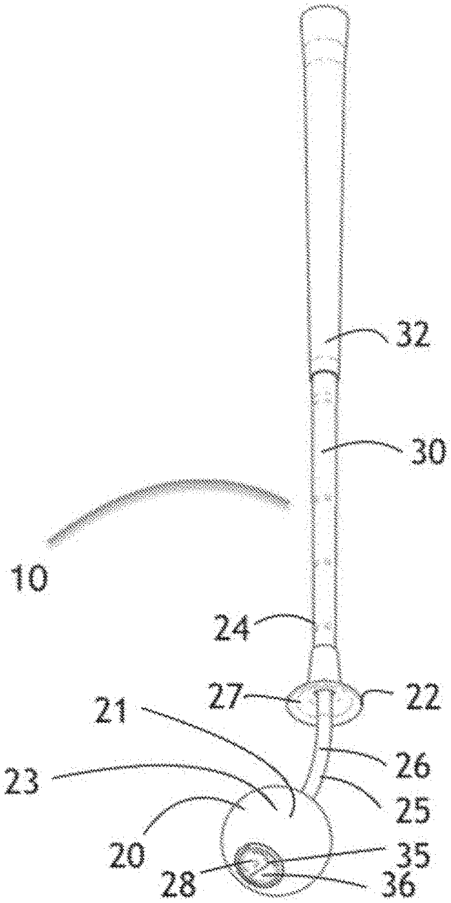
[0066] FIG. 1 is an isometric view of a first embodiment of the practice club from a distal end, with a variable-mass stopper shown in an extended position and a bit loose, only for the purposes of clarity. That is, in the rest or the swing position, the stopper would be under tension and either hard against the mounting stop cup (rest position) or extended therefrom, and under greater tension;
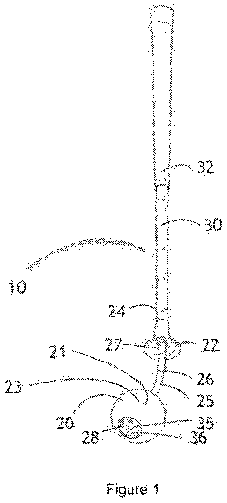
[0067] FIG. 2 is a left side view of the practice club shown in FIG. 1;
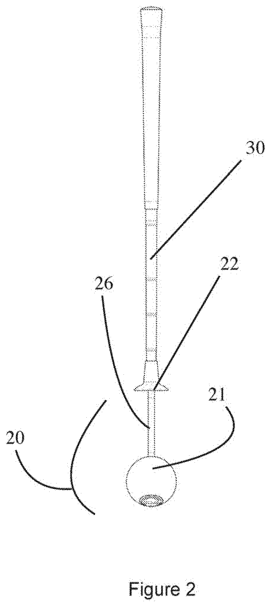
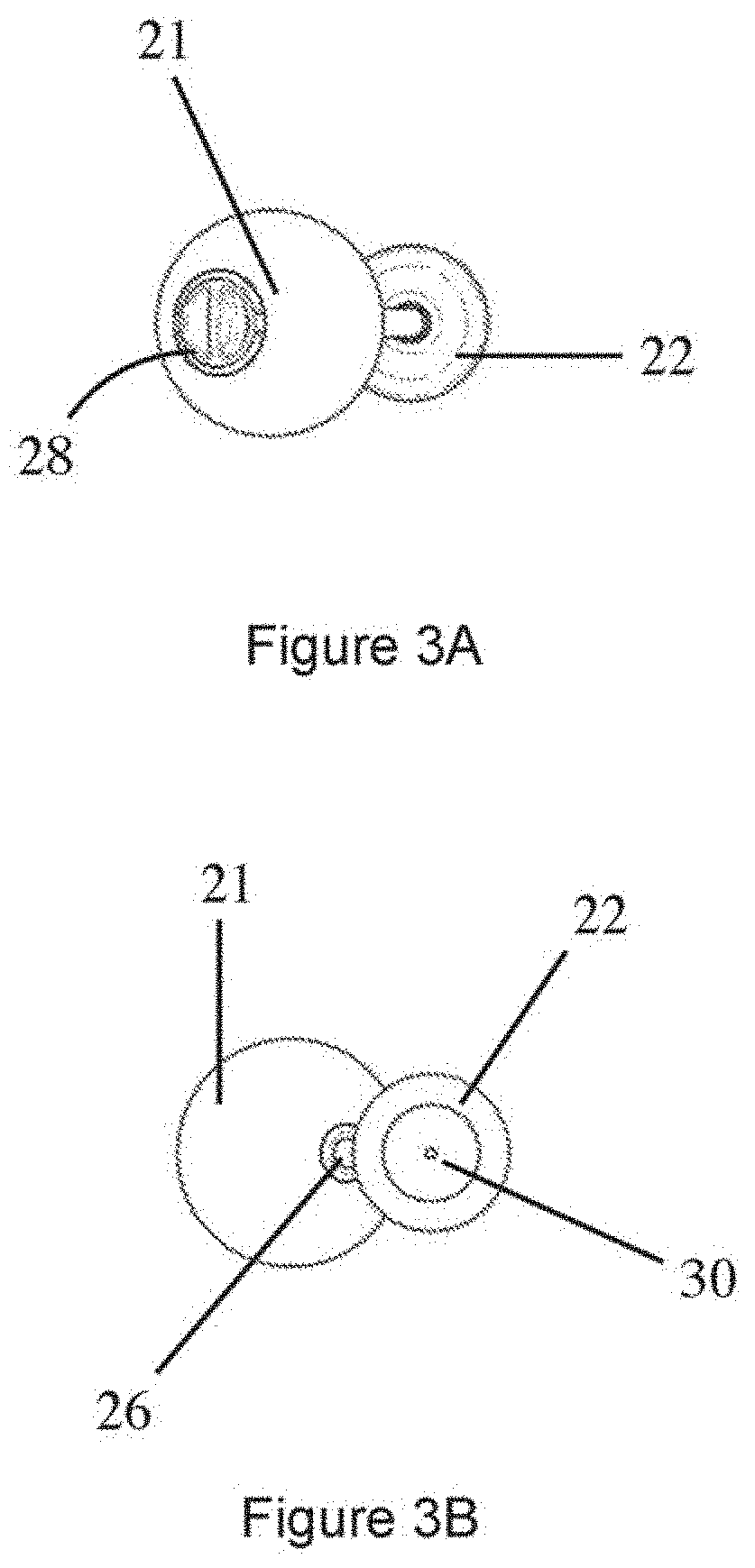
[0068] FIG. 3A is an underside view of the practice club;
[0069] FIG. 3B is a plan view of the practice club;
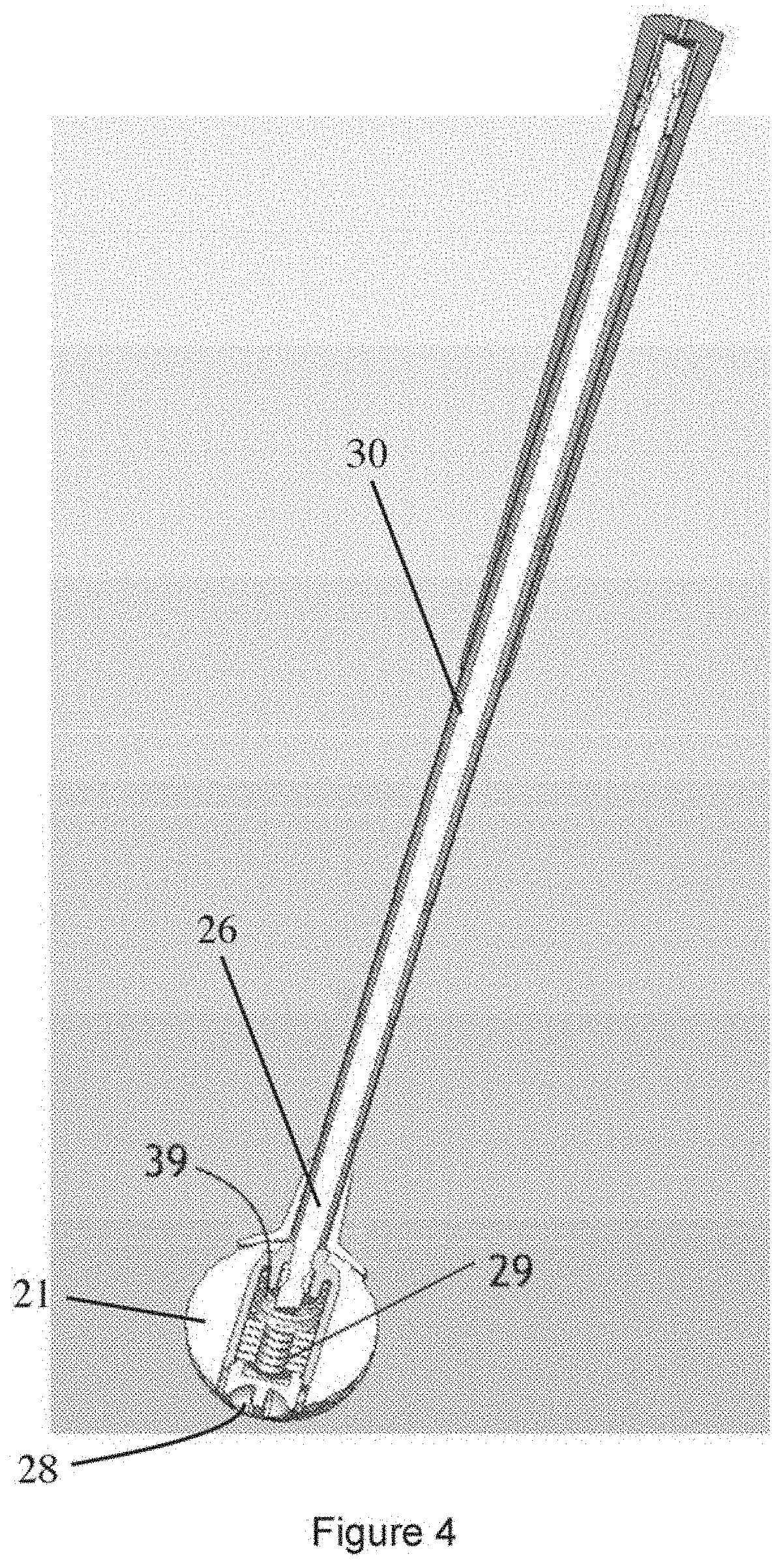
[0070] FIG. 4 is a cutaway isometric view of the practice club of FIG. 1, showing the variable mass stopper;
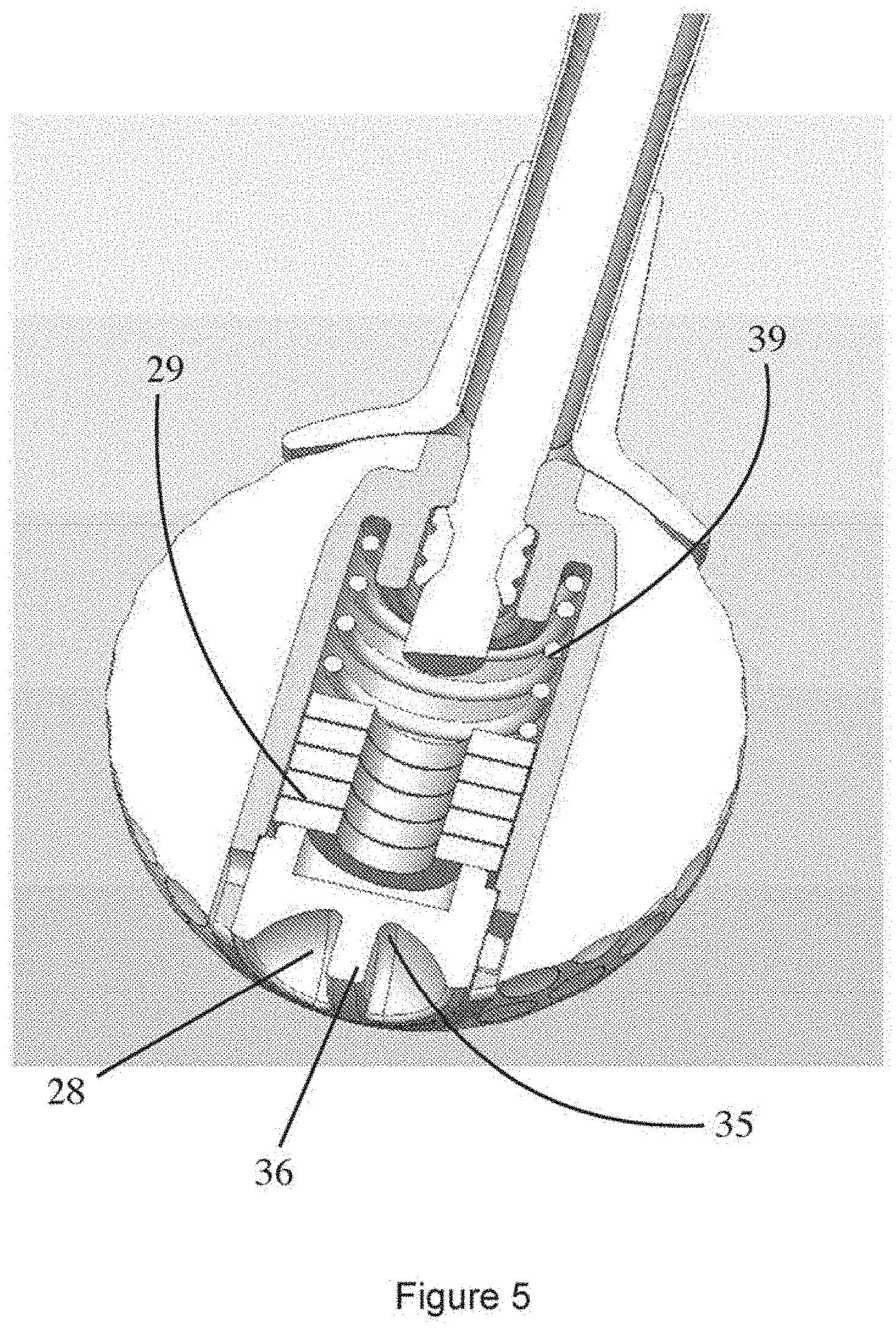
[0071] FIG. 5 is a detail view of the variable-mass stopper;
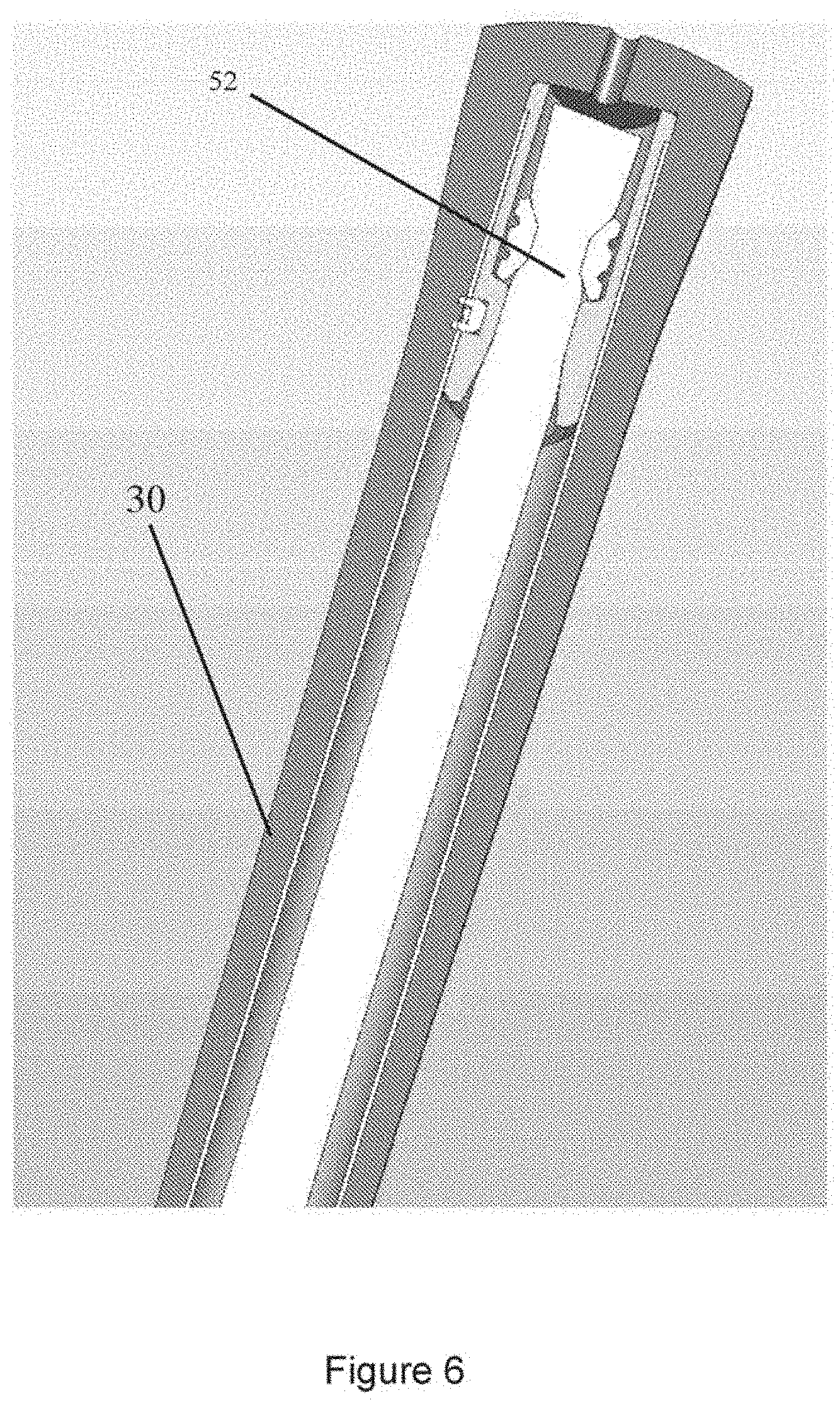
[0072] FIG. 6 is a detail view of the handle which mounts the resilient element which extends all the way down to the variable-mass stopper (not shown);
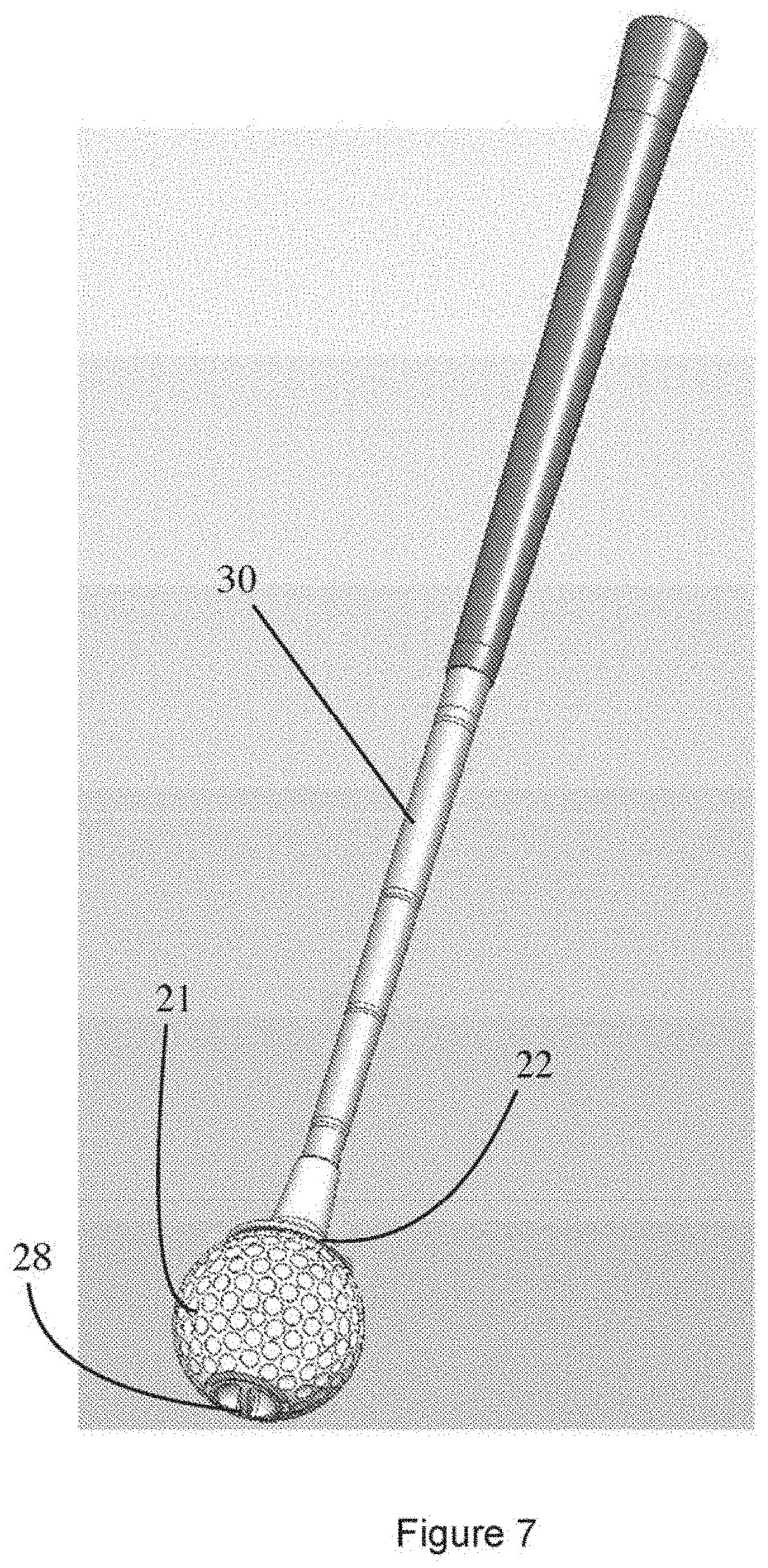
[0073] FIG. 7 is an isometric view of the embodiment shown in FIG. 1, (essentially this picture is the same as shown in FIG. 1);
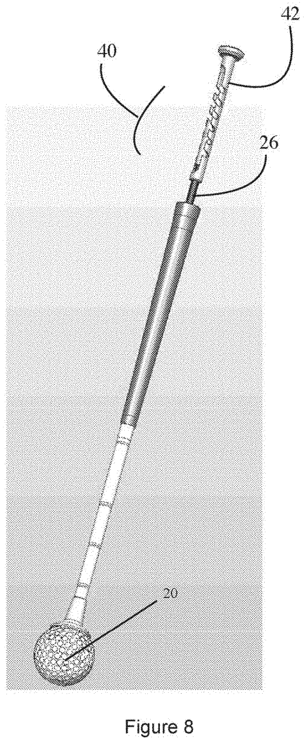
[0074] FIG. 8 is an isometric view of another embodiment of the practice club, this embodiment including a tension adjusting assembly in the handle;
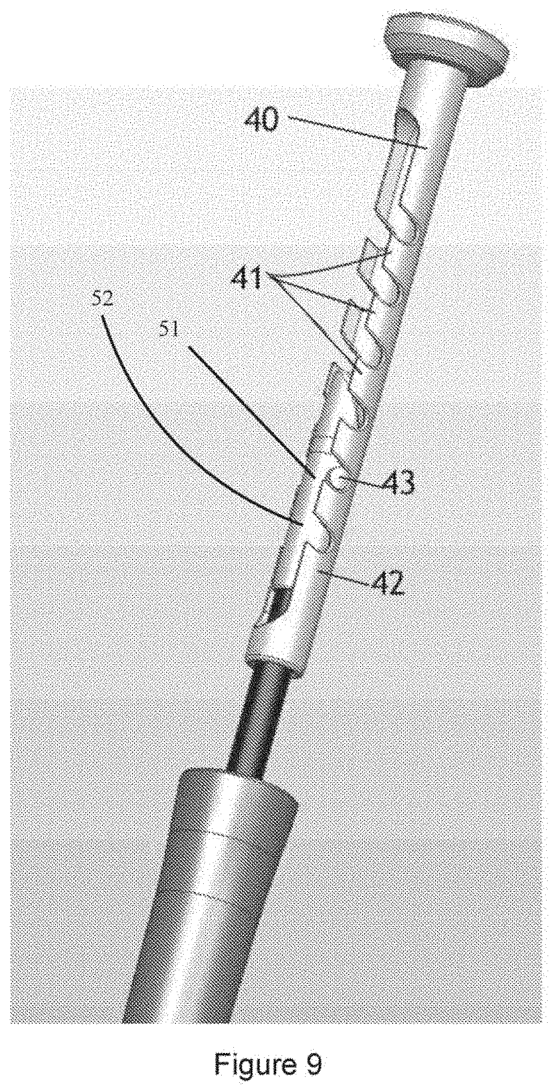
[0075] FIG. 9 is a detail view of the handle showing the tensioning assembly disposed therein;
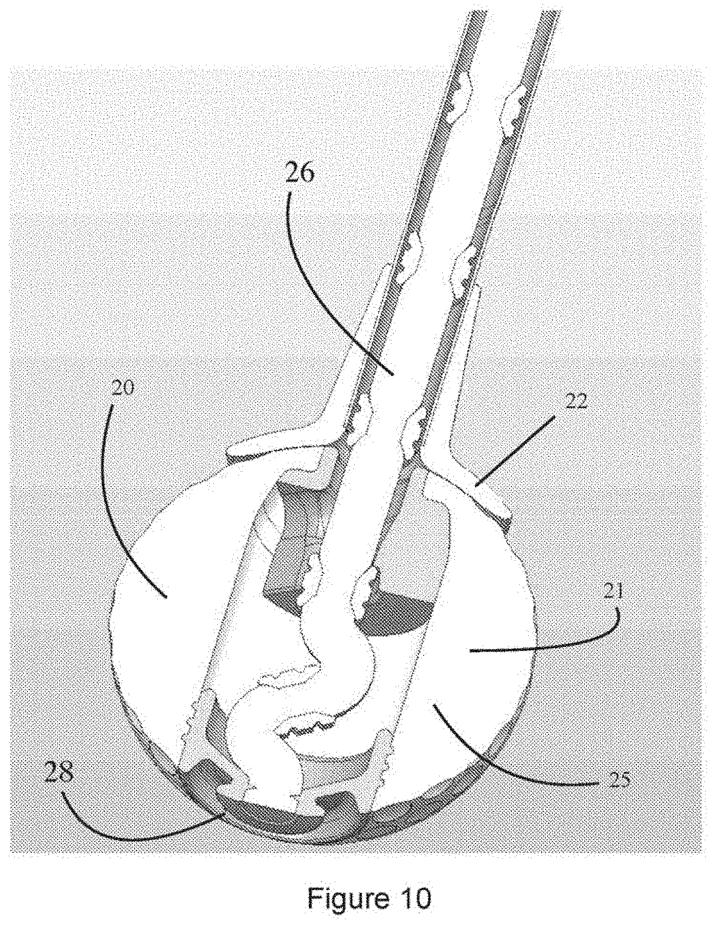
[0076] FIG. 10 is a detail cutaway view of the stopper of the second embodiment, which is not tunable as to weight;
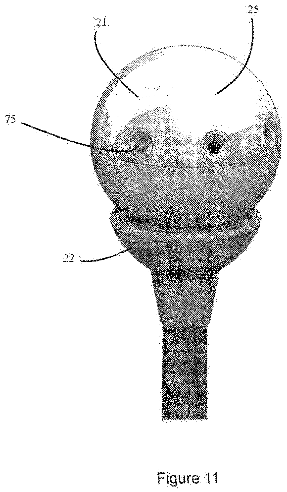
[0077] FIG. 11 is an isometric view of the distal end of a third embodiment, which is unable as to cord tension;
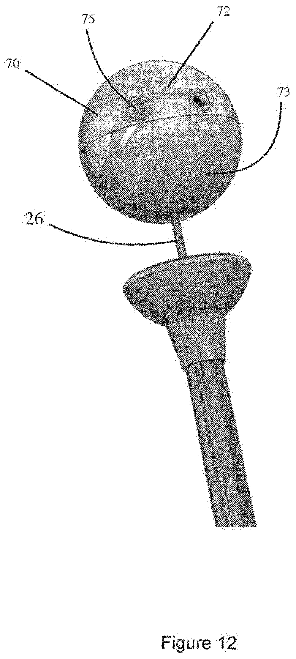
[0078] FIG. 12 is an isometric view of the distal end of the third embodiment, is an extended disposition during a good stroke;
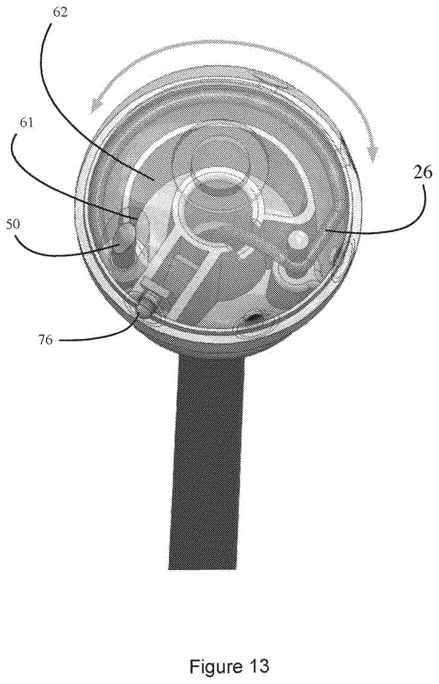
[0079] FIG. 13 is a perspective view of the distal end of the third embodiment, showing the inner workings of a cord tensioning apparatus in the stopper;
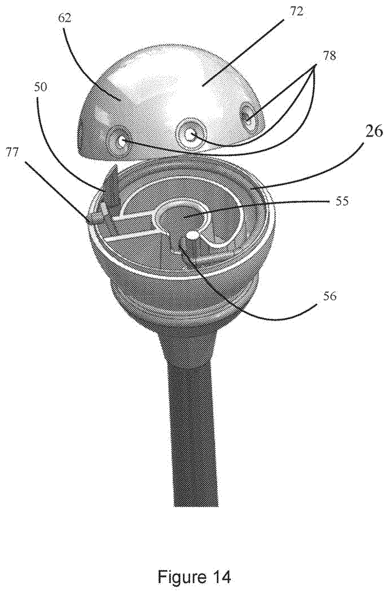
[0080] FIG. 14 is a perspective view of the distal end of the third embodiment, slightly exploded for clarity, to show the inner workings of the cord tensioning apparatus;
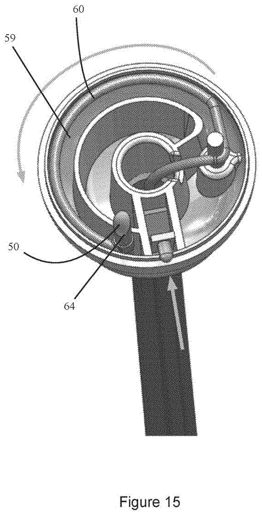
[0081] FIG. 15 is a perspective view of the distal end of the third embodiment, with the cord tensioning apparatus showing in a fully tense position (as in FIGS. 13 and 14);
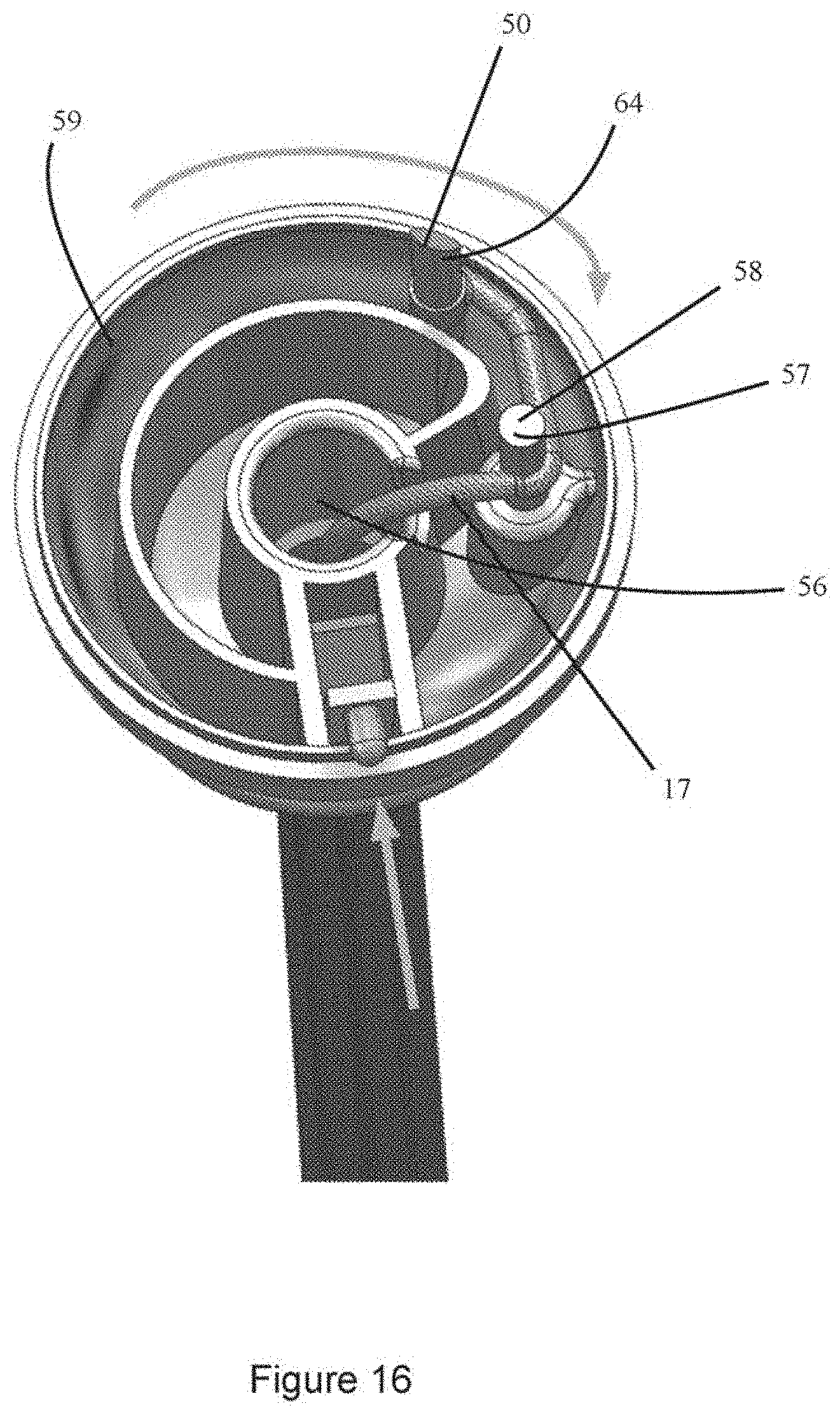
[0082] FIG. 16 is a perspective view of the distal end of the third embodiment, the tensioning device shown in a slack position;
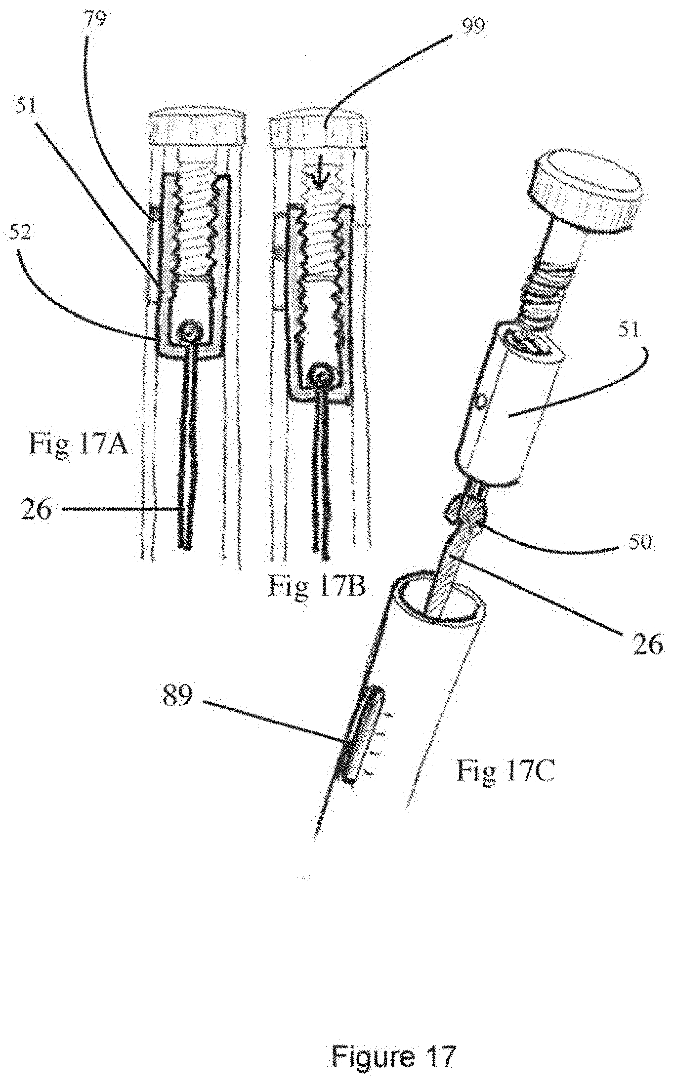
[0083] FIG. 17A is another embodiment of a tensioning device in a tense position, the tensioning device shown disposed in a handle and including a carriage and a threaded screw to tune the tension in the cord;
[0084] FIG. 17B is a section view, similar to FIG. 17A, with the carriage in a loose position;
[0085] FIG. 17C is an isometric, semi exploded view of the tension adjuster in FIGS. 17A and 17B;
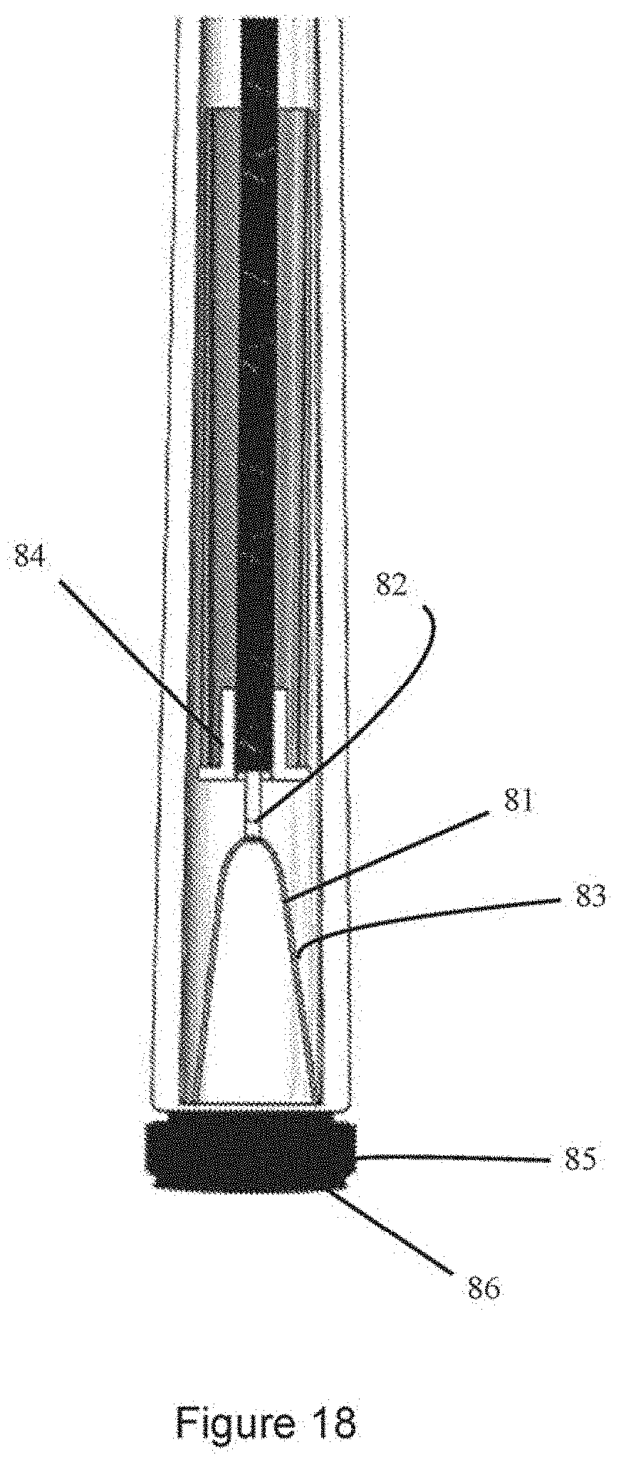
[0086] FIG. 18 is a cutaway view of another embodiment of tensioning device, in the form of a rotating;
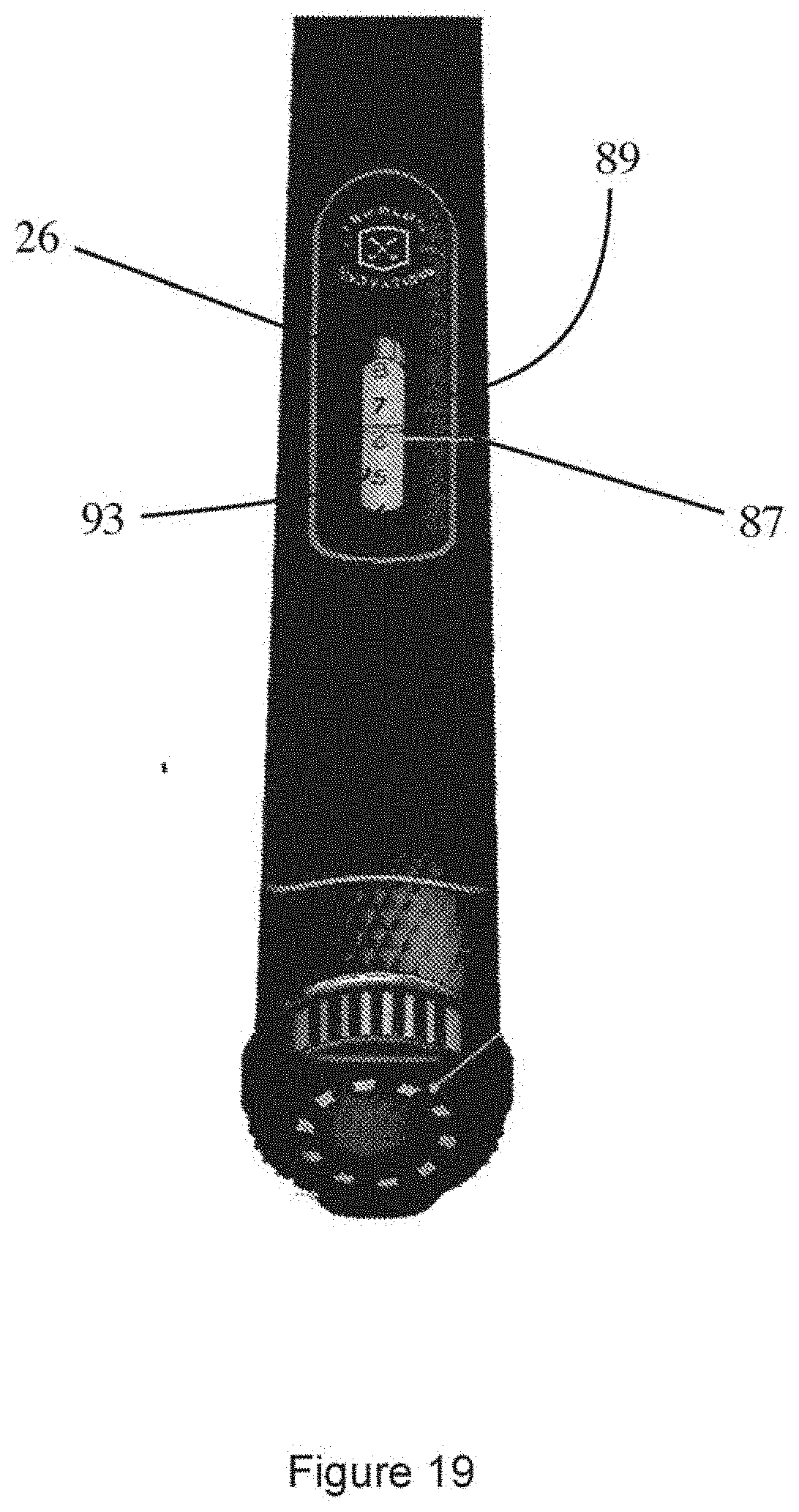
[0087] FIG. 19 is a perspective view of a tensioning indicator gauge mounted on the handle which may be used with any of the embodiments of tensioners;
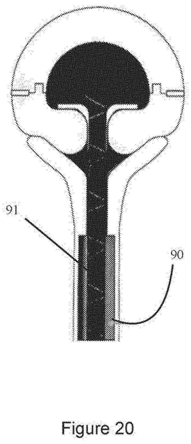
[0088] FIG. 20 is a section view of the distal end of the practice club showing an embodiment of elastic cord support which includes a collar to reduce wear; and
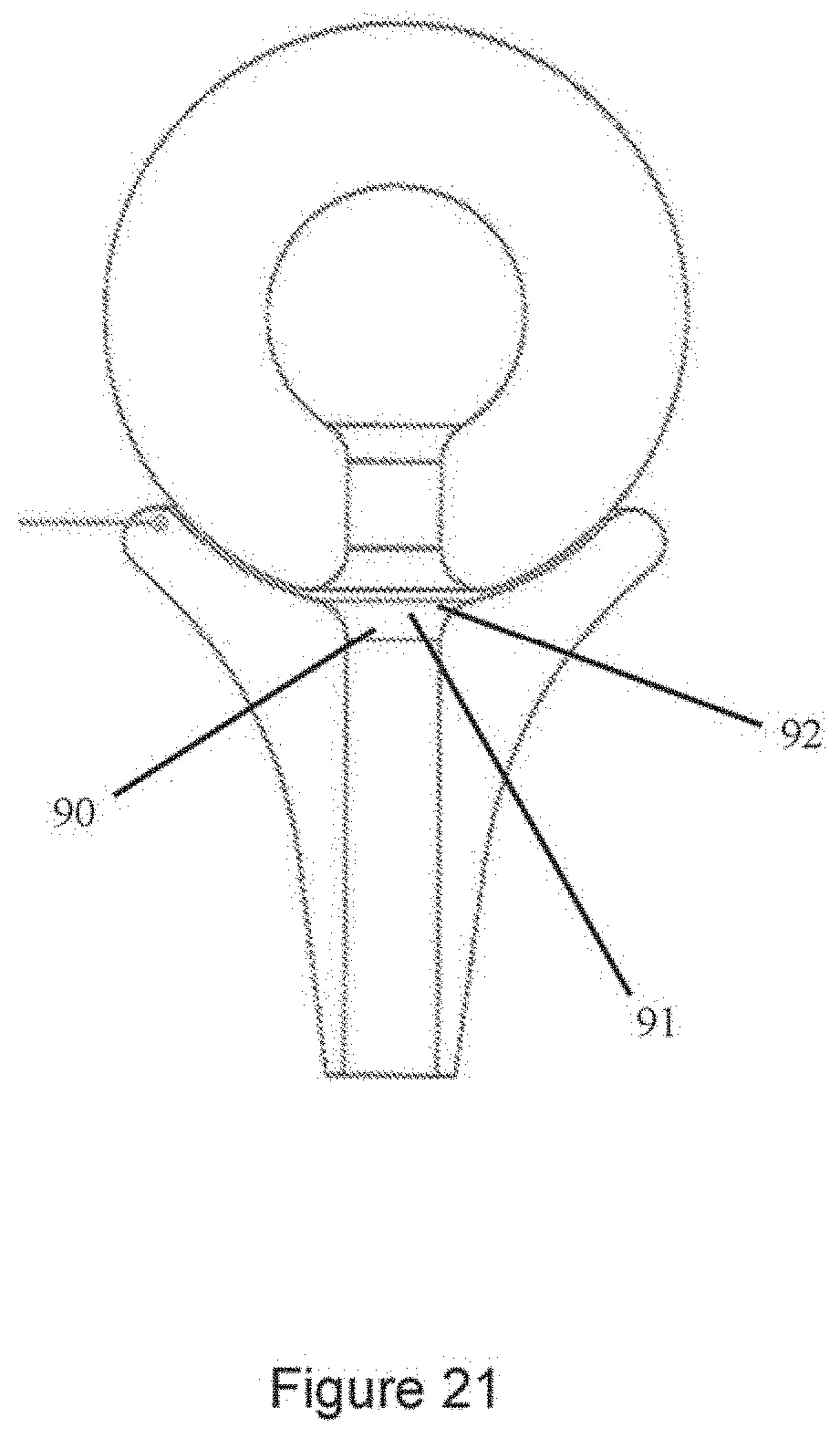
[0089] FIG. 21 is a section view of the distal end of the practice club showing another embodiment of elastic cord support which includes a collar with flanges extending radially therefrom;
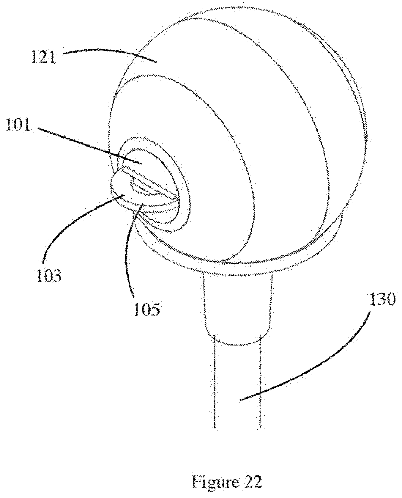
[0090] FIG. 22 is an isometric view of a distal end of a fourth embodiment of practice club, with a grip shown in a deployed position;
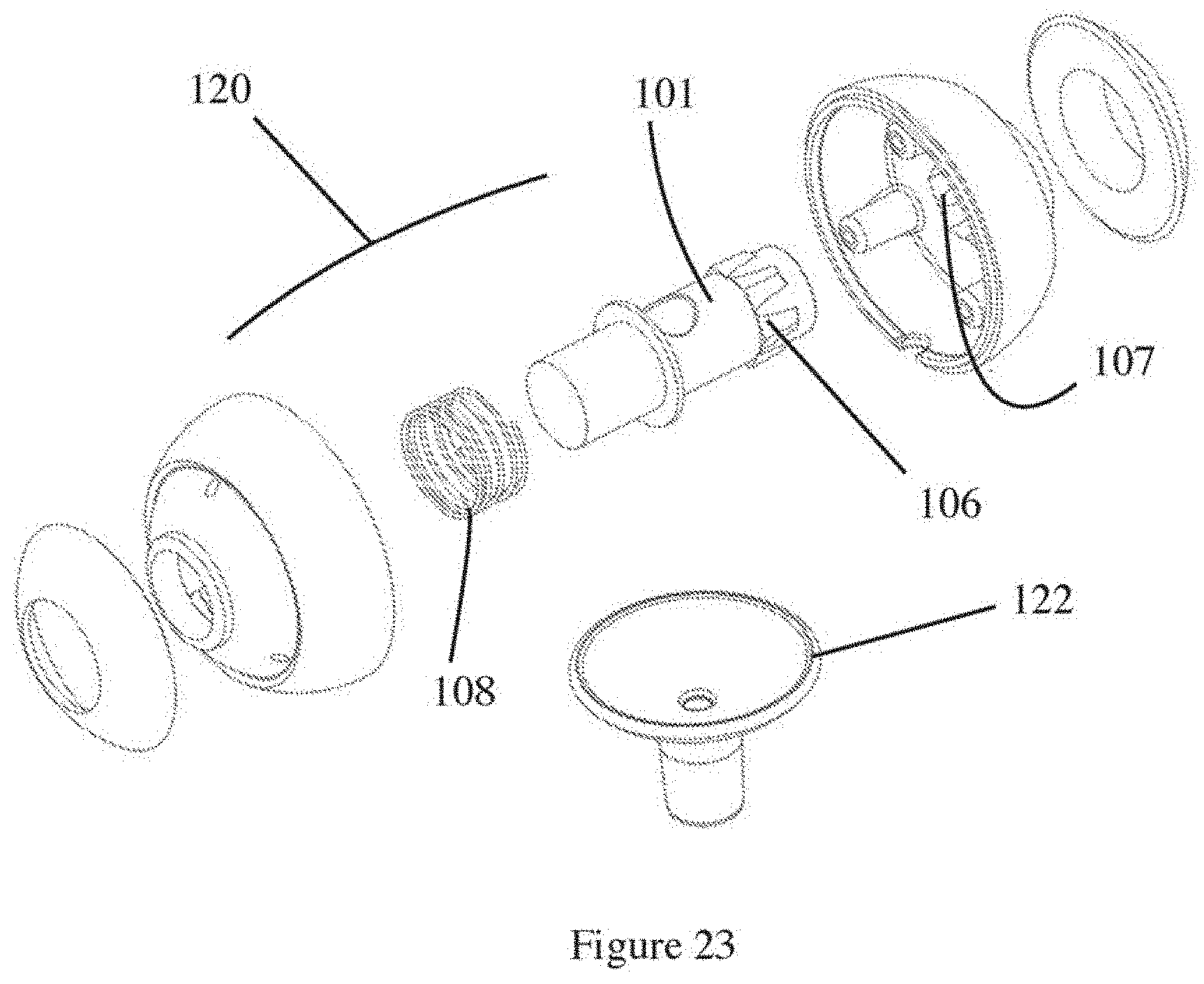
[0091] FIG. 23 is an exploded view of the distal end of the fourth embodiment of practice club;
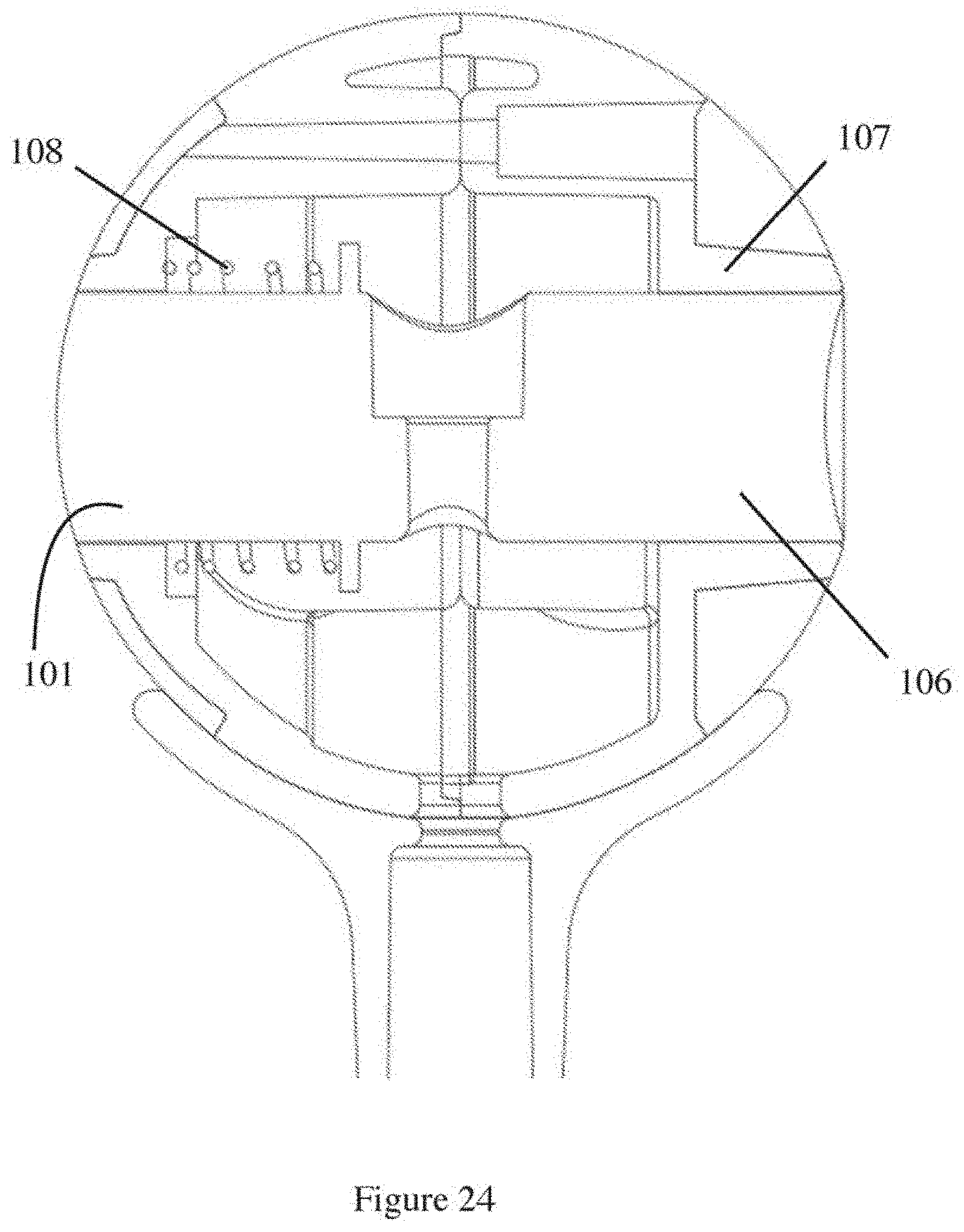
[0092] FIG. 24 is a section view of the fourth embodiment shown in FIGS. 22 and 23, with the cord removed for clarity;
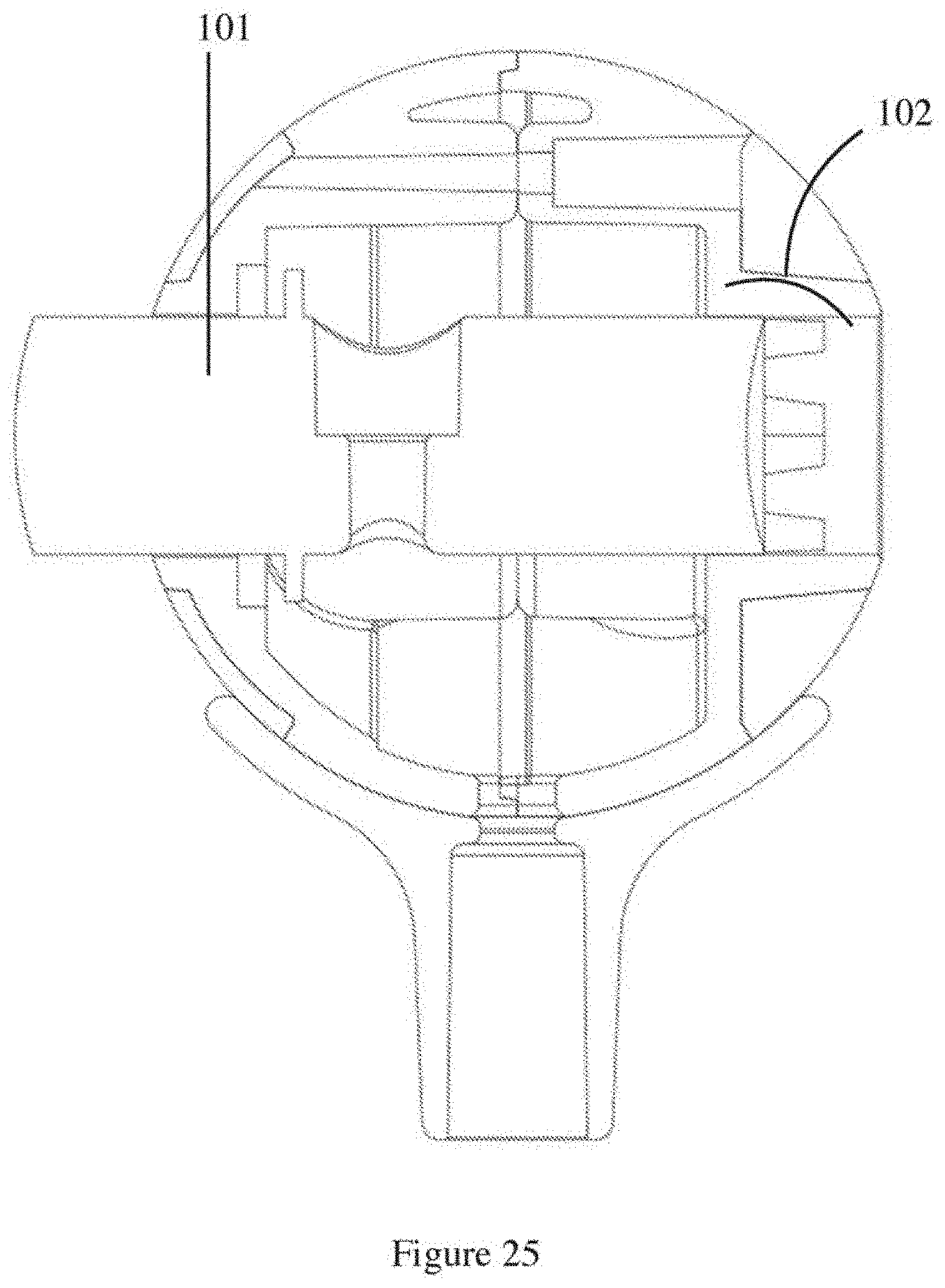
[0093] FIG. 25 is a section view of the fourth embodiment, with an axle clutch in a disengaged position and the cord removed for clarity;
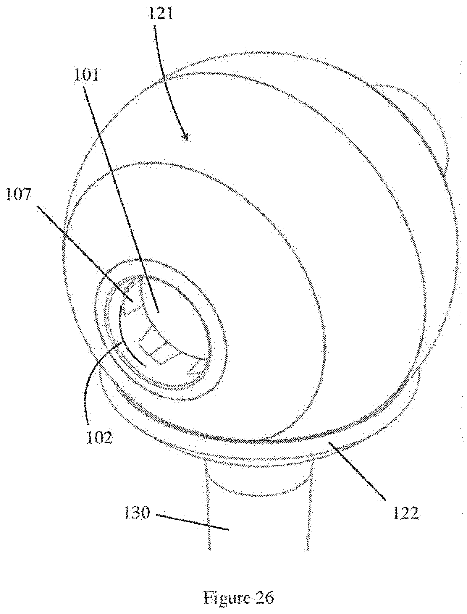
[0094] FIG. 26 is an isometric view of the fourth embodiment, with the axle clutch shown in a disengaged position for tensioning or release;
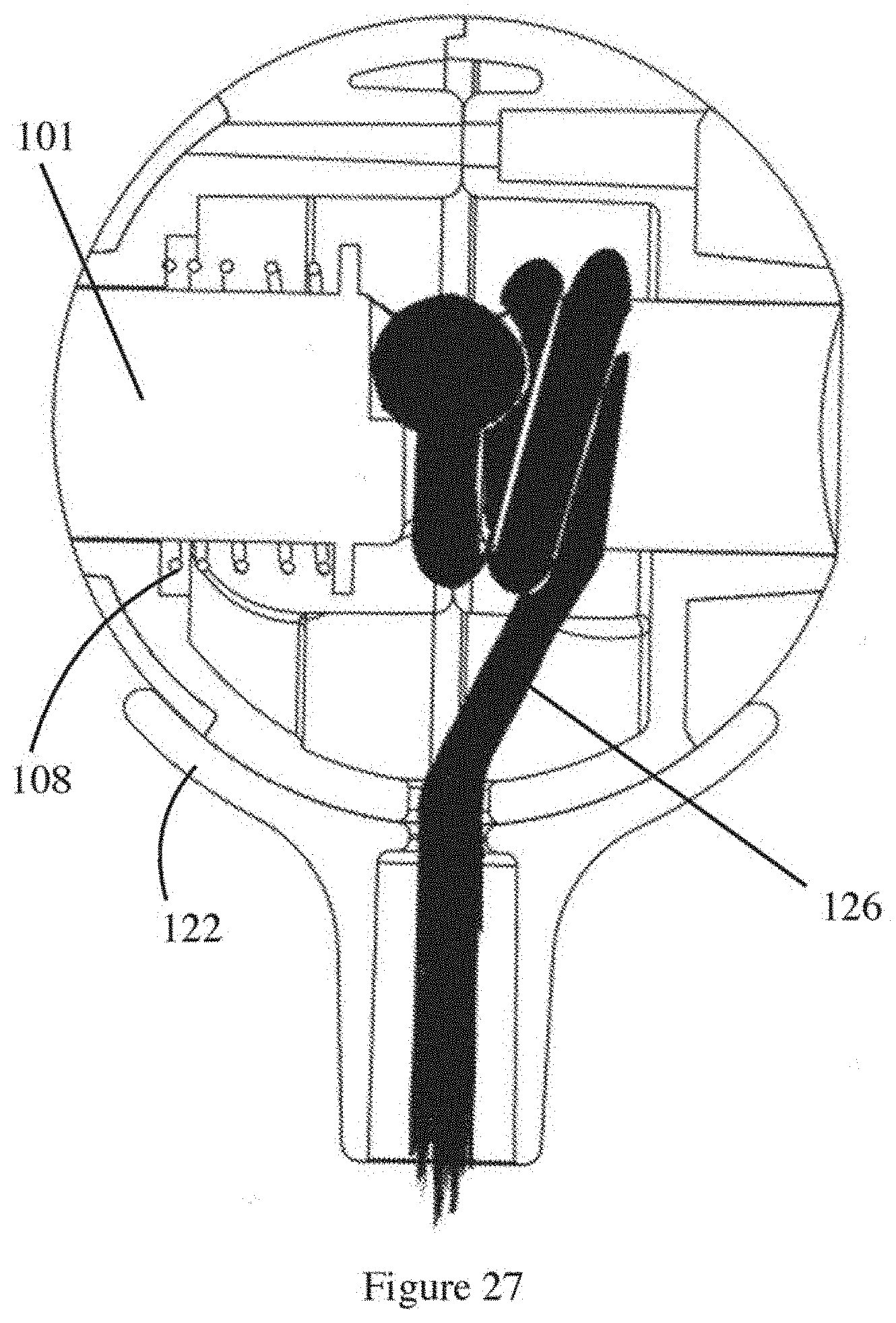
[0095] FIG. 27 is a section view of the distal end of the fourth embodiment, clutch engaged, with cord shown in a tensioned position around the axle;
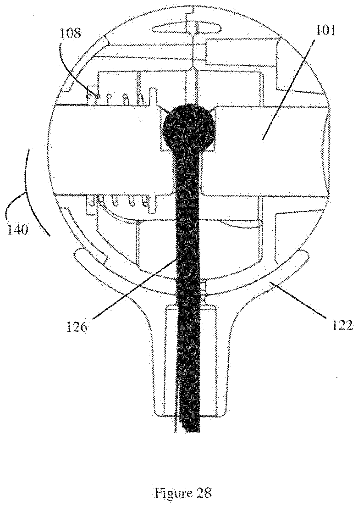
[0096] FIG. 28 is a section view of the distal end of the fourth embodiment, clutch engaged, with the cord shown in a release position on the axle;
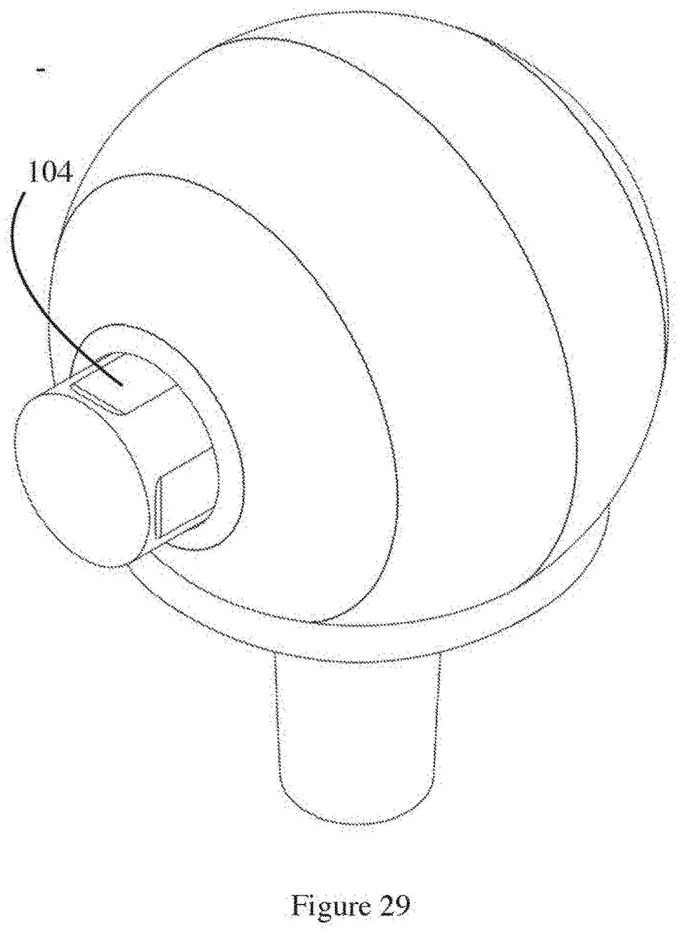
[0097] FIG. 29 is a section view of the distal end of the fourth embodiment, axle clutch disengaged, showing grip elements on the exposed axle end to facilitate tensioning of the cord;
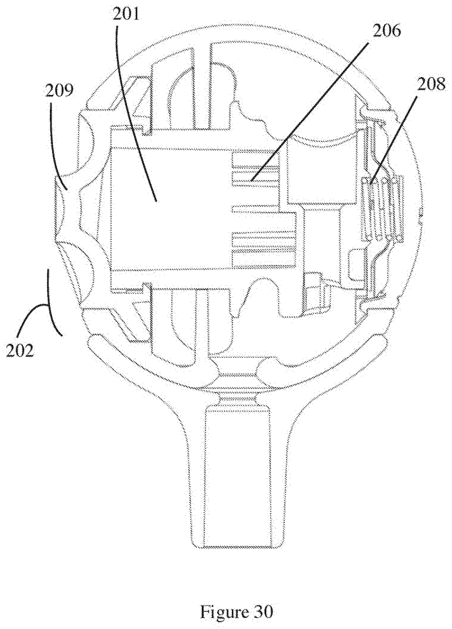
[0098] FIG. 30 is section view of the distal end of the fifth embodiment of the present technology, showing clutch ratchet in an engaged position and cord omitted for clarity;
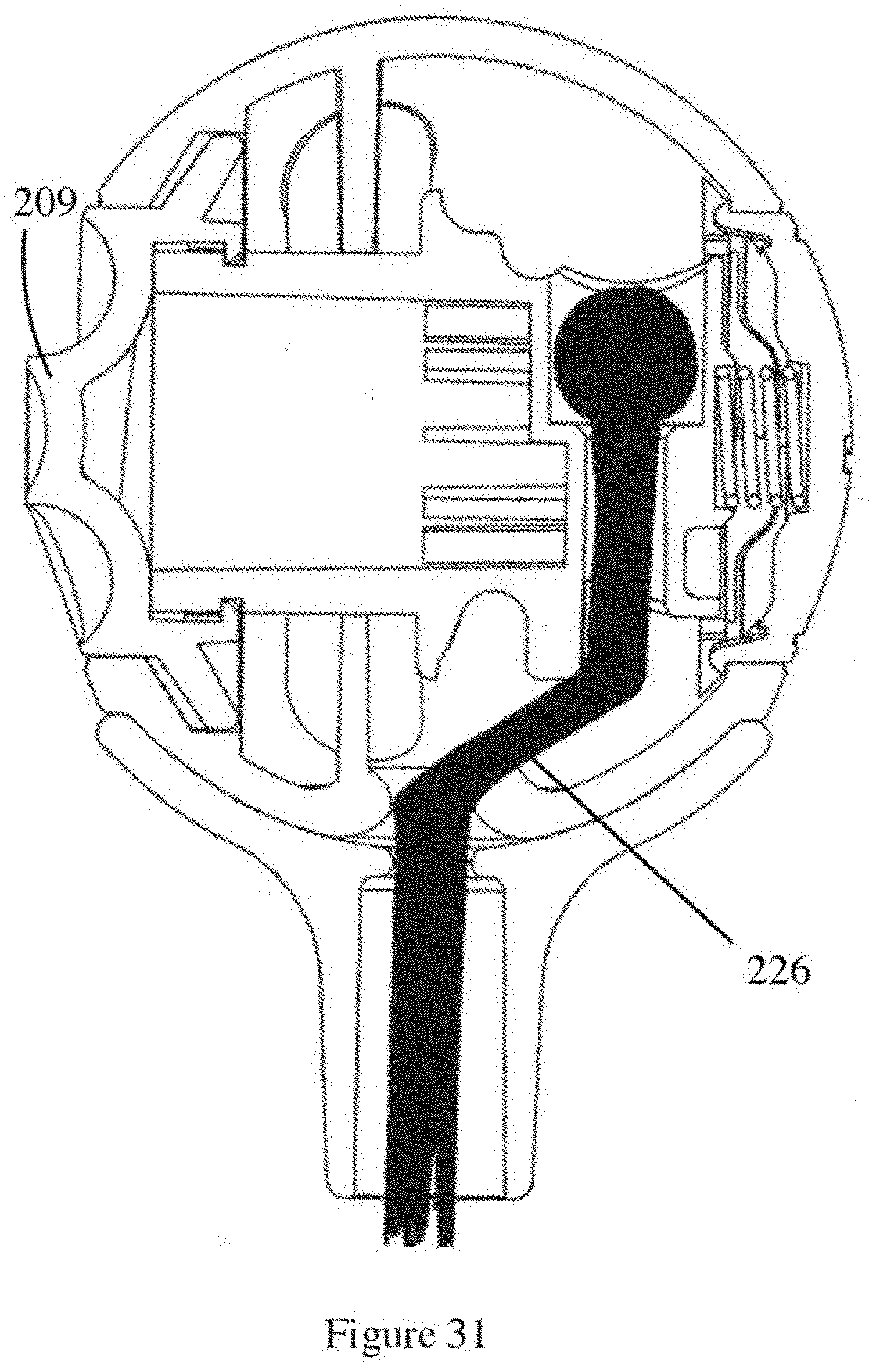
[0099] FIG. 31 is section view of the distal end of the fifth embodiment with the cord shown in a release position on the axle;
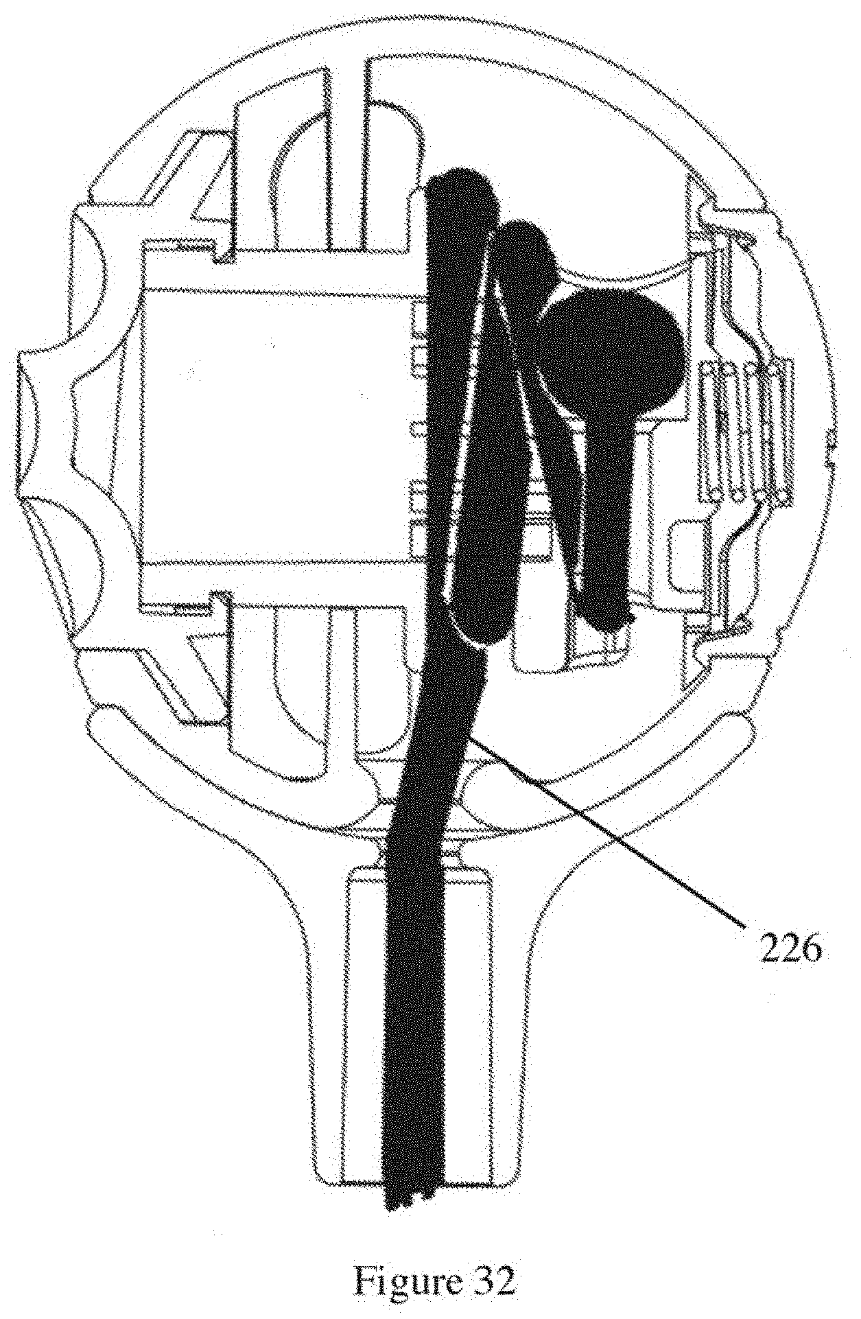
[0100] FIG. 32 is section view of the distal end of the fifth embodiment with the cord shown in a tensioned position on the axle;
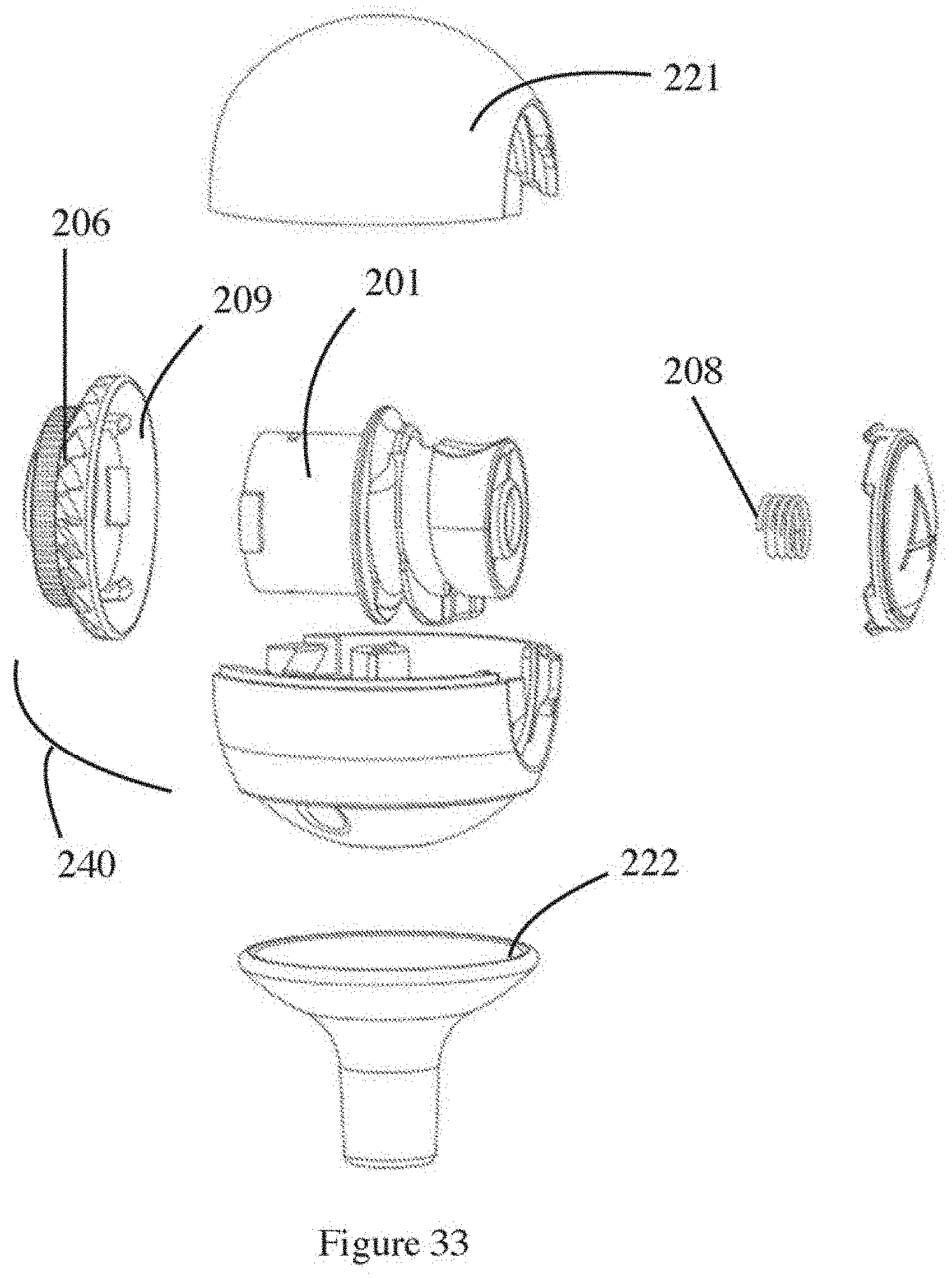
[0101] FIG. 33 is an exploded view of the distal end of the fifth embodiment, with the cord omitted for clarity; and
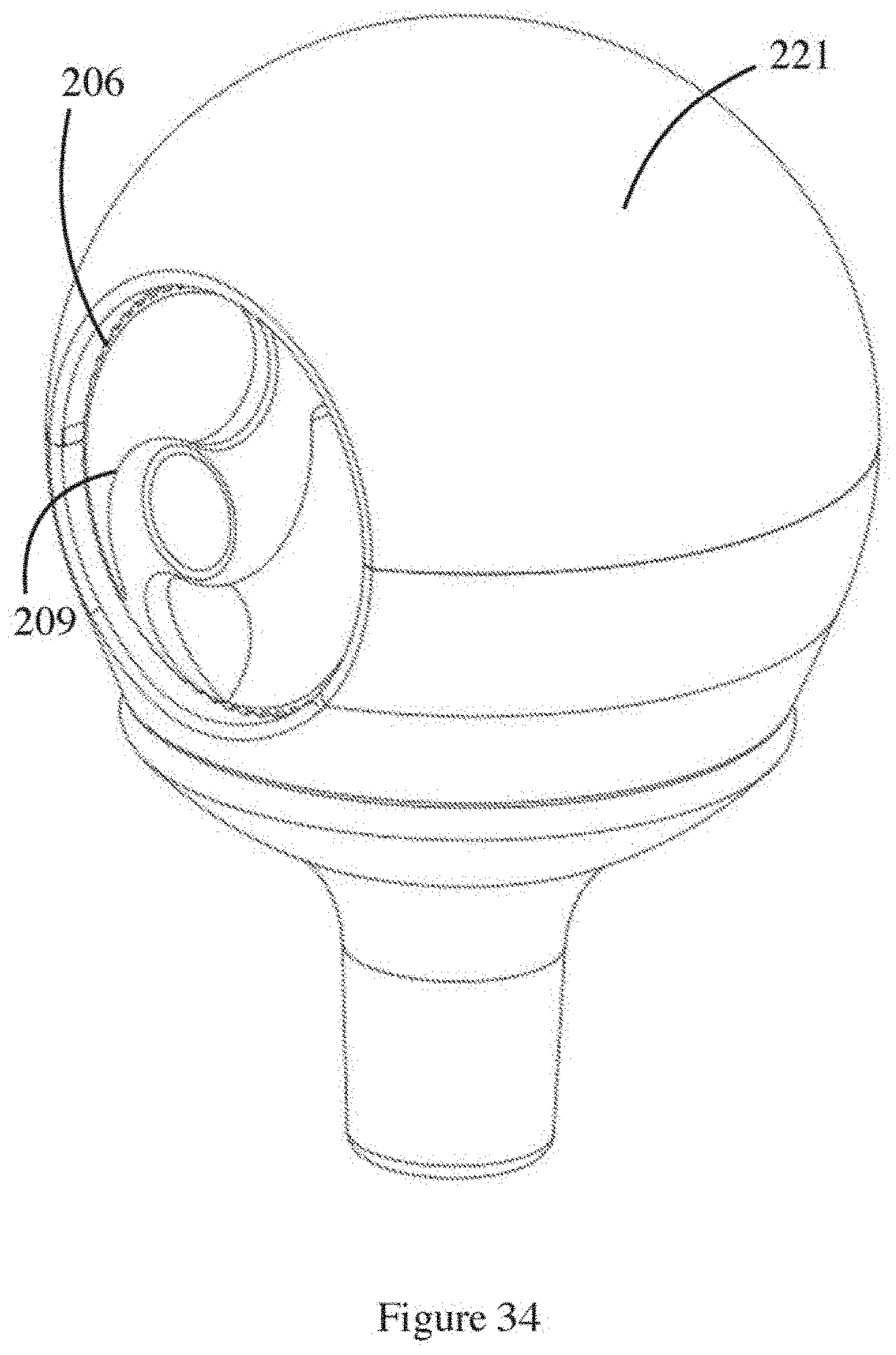
[0102] FIG. 34 is an isometric view of the distal end of the fifth embodiment, showing the stopper and clutch ratchet in a disengaged position.
DETAILED DESCRIPTION OF AN EXAMPLE EMBODIMENT
[0103] Referring to the drawings there is shown a practice club for providing feedback on a player's swing, the practice club generally indicated at 10.
[0104] In use, the practice club provides haptic feedback to a user during the user's swing, by giving the player a feeling of the downswing experience of a desirable "lag" of a club head during the downswing. Thus, the player experiences the actual physical dynamics of the desired downswing. Accordingly, all the muscles of the golfer involved in the downswing experience the desired physical dynamics and this experience is stored in the player's muscle memory. Furthermore, this experience does not need to be interpreted by the player in the same way that an instructor's verbal advice needs to be interpreted.
[0105] There may also be an additional experience of giving the player a bump from the return of an extensible stopper 20 assembly against a club shaft 30 during deceleration of the club shaft.
[0106] The arrangement is such that in use the player swings the club shaft 30 on the downswing, with the aim of accelerating it, thereby extending the extensible stopper 21, so that it leaves a mounting stop 22 on which IT no an ally resides under the centrifugal force of the downswing. A resilient cord element 26 facilitates the extension of the stopper 21 from the mounting stop 22 during the downswing, and allows the stopper 21 to extend longitudinally away from, and in a trailing direction from, the club shaft 30. The lag is partly due to the air resistance experienced by the stopper 21, and the cord 26 extension.
[0107] During the follow through, in which the club slows down, the stopper 20 snaps back into the mounting stop 22 at a selected angular position. The user feels the angular location of the lag and/or the bump, and can modify the swing next time accordingly, refining the swing so that a particular angular range from vertical is selected for the lag or the bump. This provides direct instruction on stroke technique which the body feels, rather than hears.
[0108] The extensible element 20 is in the form of a stopper 21, which itself is part of an extendible stopper assembly 25. The extendible stopper assembly 25 is configured such that the stopper 21 is movable between a rest or relaxed position in which it rests against the mounting stop 22, and an extended position in which the stopper 21 extends a selected distance from the mounting stop 22. The extendible stopper assembly 25 includes a resilient element 26 on which is mounted the stopper 21 which gives it the extendible function, snapping back on deceleration.
[0109] The club shaft 30 is a stub shaft 32, and resembles a shortened golf club, missing the typical golf club head that might be expected of a golf club. This provides an advantage that the club 10 is portable, but can still instruct and allow practice at convenient times, perhaps in indoor areas when a player cannot, for example, leave the office because of other life responsibilities.
[0110] The club shaft 30 is hollow, to receive and/or mount a portion of the resilient element 26. The resilient element is a cord, such as may be found on an octopus strap.
[0111] The arrangement of the resilient element 26 is such that the tension therein may be varied or supplemented, and one such arrangement can be seen in FIGS. 8 and 9. A tension adjuster 40 is provided and shown in FIGS. 8 and 9. The tension adjuster 40 varies the resting distance between a handle anchor 52 and a stopper anchor 50 by mounting the handle anchor 52 on a carriage 51. The carriage 51 can be selectively mounted on one of a plurality of rungs or steps or catches or hooks or the like, indicated at 41 on a tensioning insert 42. The rungs 41 are spaced along the insert 42, for to be caught by a cooperating hook 43 disposed on the carriage 51, which in turn has the resilient element 26 fastened thereto.
[0112] The mounting stop 22 is provided at a distal end 33 of the shaft. The mounting stop 22 is shown as a cup 27 for receiving the stopper 21. The mounting stop 22 is convex to receive the stopper 21 on a broad surface area, to provide a secure platform for receiving the stopper 21, and/or to make a loud sound and a confident bump during the follow through.
[0113] The mounting stop 22 is oriented to face longitudinally outward from the club shaft, to facilitate fast retraction along the centripetal plane for strong bump and noise.
[0114] While it is not shown, the distal portion of the club shaft may be configured to tilt. A joint may be provided to facilitate the tilt. A known axle may provide the axis, and a pair of cooperating scalloped plates may provide a selected number of angular positions in which to mount the mounting stop 22 relative to the club shaft: 20, 25, 30, 35, 40, 45, 50, 55, 60, 65, 70, 75, 80 or 85 or 90 degrees to the club shaft. The stopper 21 is in the form of a ball 23 such as a baseball-shaped element, so that it cannot retract up the handle through a mounting stop aperture 24. There are also dimples in the stopper to affect the airflow around the stopper.
[0115] Other dynamic adjusters or pseudo-tensioning adjusters 40 operate by varying the mass of the stopper 21. The mass of the stopper 21 may be varied, so as to tailor the feel of the practice club to suit the style and strength of a player. A player may want to mimic the feel of a heavier head, or have a faster swing, and adjust the mass of the stopper accordingly. The mass of the stopper 21 may be varied by providing mass receivers on or in the stopper 21. In the embodiment shown, the stopper 21 is hollow and includes an access port 28 to receive one or more weights 29 inside. The access port 28 in one embodiment includes a closure 35 in the form of a hatch 36.
[0116] The weights 29 are held in place against one wall by a spring or resilient element 39 to stop them rattling around inside the ball 23. The spring can be arranged longitudinally to hold the closure 35 against the threads to increase friction on the threads to inhibit it being forced out of the end of the access port 28.
[0117] The resilient element is anchored at the top end of the handle to provide a low frequency of resilience.
[0118] Another arrangement of tension adjuster 40 is shown in FIGS. 11 to 16. In the arrangement shown, rather than vary the relative position between a stopper anchor 50 and a handle anchor 52 by moving the handle anchor 52 with a carriage 51, the other end is tensioned. That is, the stopper anchor 50 for the elastic cord 17 is variable in position inside the head relative to the handle anchor 52 (FIG. 6). In this embodiment, the stopper includes one or more guides to guide the cord 17 into and around the stopper 21 to control the tension. The arrangement is rather like wrapping the cord 26 horizontally about an axle. A first guide is at 54 which is an inlet guide 55, which is in the form of an aperture 56. The inlet guide 55 facilitates a radial turn in the cord 17 to a second guide 57 which is in the form of a post 58 for facilitating a tangential turn of the cord 17 so that it extends around a peripheral pathway 59 in or on the stopper. In the case where the stopper is a sphere, the peripheral path 59 is a circumferential path 60, and where the stopper is, say, a square or other polygon, the peripheral path 59 is a more angular path which may follow the periphery of the stopper.
[0119] Drawing the stopper anchor 50 around the peripheral path 59 extends the cord 17 around the peripheral path 59, tensioning the cord 17. The stopper anchor 50 is in the form of a stopper anchor post 64, and is drawn around the peripheral path 59 by an anchor driver 61 The anchor driver 61 can be moved relative to the stopper 21 by an actuator 70 mounted on the stopper wall 21. The actuator 70 in the Figures can be seen to be mounted on or in a stopper head 62. It can be seen that for ease of use, the stopper 21 is formed in two hemispheres 72, 73, which are relatively rotatable to one another. One tensioning actuator 70 is in the form of movable hemisphere 72 and the anchor driver 61 is mounted under or inside the movable hemisphere 72 of the stopper 21. The anchor driver 61 is in the form of a co-operating recess 63 to receive the stopper anchor post 64. There is a lock 75 to lock the hemispheres 72, 73 together, and actuating hemisphere 72 has a plurality of lock receivers 78 disposed around its circumference so that the user may select the tension of the cord 17. There are five lock receivers 78 shown in the Figures.
[0120] To tighten the elastic cord, the lock 75 is released by pressing a biased lock release 76 in the form of button 77 and then turning the movable hemisphere 72 around to the next lock receiver 78. To loosen, release lock and rotate hemisphere 72 back the other way.
[0121] FIG. 17 is a more user-friendly version of the tensioner shown in FIGS. 8 and 9, wherein the carriage 51 can be drawn away from the stopper 21 by mounting it on a threaded barrel, and with a pin 79, drawing the carriage 51 linearly along the barrel when the handle end 99 is rotated.
[0122] FIG. 18 shows an optional tensioning device, which is similar to the tensioner described in U.S. Pat. No. 5,934,599 to Hammerslag, the entirety of which is by this statement incorporated herein by referring to it here. To summarise that system there is a lace 81 provided, in the form of a cable 83, which extends through a low-friction guide 82 disposed on one end of a carriage 84, and a tensioning ratchet 85 disposed on the end of the handle 86. The tension in the lace 81 can be increased by rotating the actuator 85 which is in the form of a dial 86, so as to wrap the lace 81 around a spool. The low friction guide is a U-shape, to reduce friction further.
[0123] The dial can release the tension on the ratchet by pulling the dial outwards, disengaging the ratchet from a pawl.
[0124] FIG. 19 shows a tension indicator which includes a window 89 and a marking indicator 93 on the cord 26. The cord at this region of the shaft may be relatively inextensible to provide more accurate indication of tension. The cord 26 may be in two pieces: one inextensible and another extensible/resilient, to facilitate reproducible tension indication. The window may include graduations 87 at selected intervals to facilitate indication. The indicator may be used in all the embodiments described herein, except perhaps the one described and shown in FIGS. 1 to 7 where the tension is varied by adjusting the mass of the stopper 21.
[0125] FIGS. 20 and 21 show a wear protector 90 in the form of a cuff 91. In FIG. 21 the cuff 91 has flanges 92 to further reduce wear on extension and retraction.
[0126] FIGS. 22 to 29 show another embodiment of tensioning device incorporated into the stopper 21. When describing these other embodiments it is to be understood that like numerals denote like elements for example, stopper 21 is a similar element in other embodiments as 121 and 221.
[0127] The arrangement in FIGS. 22 to 29 is such that there is a stopper 121 which mounts, in a relaxed position, on mounting stop 122. The stopper 121 is a ball, and mounting stop 122 is a cooperating concave flange to provide a secure seat for the stopper 121.
[0128] The distinctive part of the embodiment is the tensioning mechanism 140. The tensioning mechanism 140 includes an axle 101 about which a resilient cord 126 can be wrapped in order to increase the tension on the stopper 121.
[0129] A clutch 102 is provided which facilitates movement between two axle positions lock and release. The locking position is shown in FIGS. 22, 24, 27, and 28 while the release position is shown in FIGS. 23, 25, 26 and 29.
[0130] The release position is wherein the axle is disposed in a sideways position, where an axle actuator may be accessible. The axle actuator is indicated at 103 and can include grips such as flats 104 shown in FIG. 25, or a deployable pivoting handle 105 shown in FIG. 22. The grips in use facilitate turning the axle 101 under greater control for increasing or decreasing the tension in the cord 126.
[0131] The clutch includes dog teeth 106 on an end portion which in use cooperate with dog teeth on a bore 107 on the stopper 121. The end of the axle 101 slides in and out of engagement with the teeth 107 to provide rotation of the axle when required. To disengage the clutch, the player pushes the axle 101 from the tooth end 106 so that the axle teeth 106 are disengaged from the bore teeth 107. The player then grabs the other end of the axle by the handle or the flats and turns the axle 101 in the desired direction to increase or decrease the tension in the cord 126. The tension indicator from FIG. 19 may be included in this embodiment to indicate the tension being increased or decreased. This assists in telling the user which way to turn the axle 101 to get the desired result: either an increase or decrease in tension, when it may not be clear from the tension on the axle 101.
[0132] The player holds the sideways pressure on the axle against the force of the biasing element 108 so as to turn the axle, and the biasing element then returns the axle teeth 106 to engagement with the teeth 107 upon release of the sideways force by the player.
[0133] The arrangement in FIGS. 30 to 34 is another embodiment, and is similar to that described and shown in relation to FIGS. 22 to 29, but with a difference in actuation and clutch.
[0134] A clutch is shown at 202 which includes an axle 201 but the axle cooperates with a ratchet cap 209 so as to turn in unison therewith. The ratchet cap 209 includes teeth 206 which cooperate with teeth on a bore 207 on the stopper 221. The axle 201 can be shifted sideways by pressure on the ratchet cap, and the user presses the axle 201 against the biasing spring 208, so that the ratchet teeth 206 disengage from bore teeth 207 (shown basically in the position of FIG. 34). The ratchet cap 209 then can be turned by using the radial shoulders and then when the desired tension (perhaps shown on tensioning indicator of FIG. 19) is reached, the sideways force is released and the axle returns to the engaged position under the biasing force of the spring 208.
Clarifications
[0135] Modifications and improvements to the invention will be readily apparent to those skilled in the art. Such modifications and improvements are intended to be within the scope of this invention.
* * * * *
D00000
D00001
D00002
D00003
D00004
D00005
D00006
D00007
D00008
D00009
D00010
D00011
D00012
D00013
D00014
D00015
D00016
D00017
D00018
D00019
D00020
D00021
D00022
D00023
D00024
D00025
D00026
D00027
D00028
D00029
D00030
D00031
D00032
D00033
D00034
XML
uspto.report is an independent third-party trademark research tool that is not affiliated, endorsed, or sponsored by the United States Patent and Trademark Office (USPTO) or any other governmental organization. The information provided by uspto.report is based on publicly available data at the time of writing and is intended for informational purposes only.
While we strive to provide accurate and up-to-date information, we do not guarantee the accuracy, completeness, reliability, or suitability of the information displayed on this site. The use of this site is at your own risk. Any reliance you place on such information is therefore strictly at your own risk.
All official trademark data, including owner information, should be verified by visiting the official USPTO website at www.uspto.gov. This site is not intended to replace professional legal advice and should not be used as a substitute for consulting with a legal professional who is knowledgeable about trademark law.