Cable Assembly Modules Detachably Mounted Upon Corresponding Circuit Pads
ZHENG; JIE ; et al.
U.S. patent application number 16/989785 was filed with the patent office on 2021-02-11 for cable assembly modules detachably mounted upon corresponding circuit pads. The applicant listed for this patent is FOXCONN INTERCONNECT TECHNOLOGY LIMITED, FOXCONN (KUNSHAN) COMPUTER CONNECTOR CO., LTD.. Invention is credited to TERRANCE F. LITTLE, JIE ZHENG.
| Application Number | 20210044040 16/989785 |
| Document ID | / |
| Family ID | 1000005049474 |
| Filed Date | 2021-02-11 |


View All Diagrams
| United States Patent Application | 20210044040 |
| Kind Code | A1 |
| ZHENG; JIE ; et al. | February 11, 2021 |
CABLE ASSEMBLY MODULES DETACHABLY MOUNTED UPON CORRESPONDING CIRCUIT PADS
Abstract
A cable assembly module includes: a front mating member; a rear cable linked behind the mating member and including a pair of signal wires; a pair of signal contacts retained upon the front mating member, each of said signal contacts including a middle retaining section associated with the front mating member, a front mating section spaced from the front mating member in a deflectable manner, and a rear connecting section mechanically and electrically connected to the corresponding signal wires, respectively; and a pair of grounding contacts located by two sides of the pair of signal contacts; wherein the front mating sections are adapted for being directly mated with circuit pads of a printed circuit board disposed in a plane, and the rear cable extends along a direction inclined with the plane
| Inventors: | ZHENG; JIE; (Rowland-Heights, CA) ; LITTLE; TERRANCE F.; (Fullerton, CA) | ||||||||||
| Applicant: |
|
||||||||||
|---|---|---|---|---|---|---|---|---|---|---|---|
| Family ID: | 1000005049474 | ||||||||||
| Appl. No.: | 16/989785 | ||||||||||
| Filed: | August 10, 2020 |
Related U.S. Patent Documents
| Application Number | Filing Date | Patent Number | ||
|---|---|---|---|---|
| 62885204 | Aug 10, 2019 | |||
| 62959886 | Jan 11, 2020 | |||
| Current U.S. Class: | 1/1 |
| Current CPC Class: | H01R 13/405 20130101; H01R 13/631 20130101; H01R 12/714 20130101; H01R 13/518 20130101; H01R 13/6581 20130101; H01R 13/6597 20130101; H05K 2201/10325 20130101; H05K 1/11 20130101; H01R 25/00 20130101 |
| International Class: | H01R 12/71 20060101 H01R012/71; H01R 13/6581 20060101 H01R013/6581; H01R 25/00 20060101 H01R025/00; H01R 13/6597 20060101 H01R013/6597; H01R 13/405 20060101 H01R013/405; H01R 13/631 20060101 H01R013/631; H05K 1/11 20060101 H05K001/11; H01R 13/518 20060101 H01R013/518 |
Claims
1. A cable assembly module comprising: a front mating member; a rear cable linked behind the mating member and including a pair of signal wires; a pair of signal contacts retained upon the front mating member, each of said signal contacts including a middle retaining section associated with the front mating member, a front mating section spaced from the front mating member in a deflectable manner, and a rear connecting section mechanically and electrically connected to the corresponding signal wires, respectively; and a pair of grounding contacts located by two sides of the pair of signal contacts; wherein the front mating sections are adapted for being directly mated with circuit pads of a printed circuit board lying in a plane, and the rear cable extends along a direction inclined with the plane.
2. The cable assembly module as claimed in claim 1, further comprising a shielding shell forms a dividing wall so as to perform shielding effect between the front mating member of one cable assembly module in a front row and that of another cable assembly module in a rear row which are densely arranged with each other in a front-to-back direction.
3. The cable assembly module as claimed in claim 2, wherein the shielding shell comprises an inner shielding shell enclosing a front portion of the rear cable, the rear cable comprising a grounding wire electrically connected with the inner shielding shell.
4. The cable assembly module as claimed in claim 3, wherein the shielding shell comprises an outer shielding shell enclosing and electrically connected with the inner shielding shell.
5. The cable assembly module as claimed in claim 4, wherein the outer shielding shell is electrically connected with the pair of the grounding contacts.
6. The cable assembly module as claimed in claim 4, wherein the dividing wall is unitarily formed on the outer shielding shell.
7. The cable assembly module as claimed in claim 4, wherein the outer shielding shell forms an opening in front of the dividing wall, and the mating member extends downwardly through the opening.
8. The cable assembly module as claimed in claim 2, wherein a rear side of the mating member is recessed to receive the dividing wall therein.
9. The cable assembly module as claimed in claim 1, wherein the middle retaining section grasps the front mating member, and the mating member forms grooves to receive front ends of the corresponding signal contacts, respectively.
10. The cable assembly module as claimed in claim 1, wherein the front mating member comprise an outer member and an inner member received in the outer member, the pair of grounding contacts molded in the outer member, the pair of signal contacts molded in the inner member.
11. The cable assembly module as claimed in claim 10, wherein the outer member comprises a first side wall, a second side wall spaced apart from and parallel to the first side wall, a connecting wall connected therebetween, and a receiving space formed by the first side wall, the second wall and the connecting wall, the inner member received in the receiving space.
12. The cable assembly module as claimed in claim 11, wherein one of the grounding contacts is molded in the first side wall, and the other one of the grounding contacts is molded in the second side wall.
13. The cable assembly module as claimed in claim 12, wherein the pair of grounding contacts comprises a bridge member connected therebetween, the bridge molded in the connecting wall, the rear cable comprising a grounding wire mechanically and electrically connected to the bridge member.
14. The cable assembly module as claimed in claim 1, further comprising a case enclosing the front mating member, the case comprising guiding protrusion on exterior surface.
15. An electrical assembly comprising: a printed circuit board having two rows of circuit pads thereon; a retainer assembled upon the printed circuit board to cover said circuit pads; two rows of identical cable assembly modules spaced from each other in a front-to-back direction, each of said cable assembly modules comprising a front mating member with corresponding contacts thereon, and a rear cable mechanically and electrically connected to the contacts; wherein the cable assembly modules are assembled into the retainerin an oblique manner.
16. The electrical assembly as claimed in claim 15, wherein the retainer comprises an upper inclined wall, and a lower inclined wall spaced apart from and parallel to the upper inclined wall, and a inclined channel formed therebetween for the cable assembly modules being entered into the retainer to mate with the circuit pads.
17. The electrical assembly as claimed in claim 15, further comprising a case enclosing the cable assembly modules, the case comprising a guiding protrusion on exterior surface, the retainer comprising a guiding groove for guiding the guiding protrusion.
18. An electrical assembly comprising: a retainer defining an internal space and a bottom face adapted to be mounted to a printed circuit board having corresponding pads thereon wherein the bottom face forms an opening to allow the internal space to downwardly communicate with the pads of the printed circuit board; two sets of cable modules commonly located within the internal space and spaced from each other in a front-to-back direction, each set of cable modules including an elongated unitary housing enclosing a plurality of units along a transverse direction perpendicular to the front-to-back direction, each unit including a mating member equipped with the signal contacts while the unitary housing being equipped with grounding contacts, both said signal contacts and said grounding contacts having rear/upper connecting portions mechanically and electrically connected to corresponding cables, and front/lower mating portions exposed around the bottom face of the retainer and adapted to be mated with the corresponding pads.
19. The electrical assembly as claimed in claim 18, wherein said two sets of cable modules are commonly enclosed within a case which has guiding mechanism so as to be assembled into the internal space of the retainer in an oblique direction perpendicular to both the transverse direction and the front-to-back direction.
20. The electrical assembly as claimed in claim 19, wherein each housing has a pair of guiding rails on two sides so as to guidably assemble the housing into the case, and the guiding rail extends in a direction oblique to an extension direction of the case.
Description
BACKGROUND OF THE INVENTION
1. Field of the Invention
[0001] The present invention relates generally to an electrical connector assembly module, and more particularly to the cable assembly modules detachably mounted upon corresponding circuit pads on a printed circuit board.
2. Description of Related Art
[0002] It is desirable to use multiple identical cable assembly modules densely arranged with one another on the printed circuit board for data transmission. Anyhow, the shielding effect is desired not only of the respective cable assembly modules but also between the neighboring cable assembly modules.
SUMMARY OF THE INVENTION
[0003] An object of the invention is to provide a cable assembly module having low profile.
[0004] To achieve the above-mentioned object, a cable assembly module comprises: a front mating member; a rear cable linked behind the mating member and including a pair of signal wires; a pair of signal contacts retained upon the front mating member, each of said signal contacts including a middle retaining section associated with the front mating member, a front mating section spaced from the front mating member in a deflectable manner, and a rear connecting section mechanically and electrically connected to the corresponding signal wires, respectively; and a pair of grounding contacts located by two sides of the pair of signal contacts; wherein the front mating sections are adapted for being directly mated with circuit pads of a printed circuit board disposed in a plane, and the rear cable extends along a direction inclined with the plane.
[0005] Another object of the invention is to provide an electrical assembly having low profile.
[0006] To achieve the above-mentioned object, an electrical assembly comprises: a printed circuit board having two rows of circuit pads thereon; a retainer assembled upon the printed circuit board to cover said circuit pads; two rows of identical cable assembly modules spaced from each other in a front-to-back direction, each of said cable assembly modules comprising a front mating member with corresponding contacts thereon, and a rear cable mechanically and electrically connected to the contacts; wherein the cable assembly modules are assembled into the retainer in an oblique manner.
BRIEF DESCRIPTION OF THE DRAWINGS
[0007] FIG. 1 is a perspective view of a first embodiment of an electrical assembly according to the invention;
[0008] FIG. 2 is a side view of the electrical assembly of FIG. 1;
[0009] FIG. 3 is a bottom view of the electrical assembly of FIG. 1;
[0010] FIG. 4 is an exploded perspective view of the electrical assembly of FIG. 1;
[0011] FIG. 5(A) is a further exploded view of the electrical assembly of FIG. 4;
[0012] FIG. 5(B) is another exploded perspective view of the electrical assembly of FIG. 5(A);
[0013] FIG. 6(A) is a further exploded perspective view of the electrical assembly of FIG. 5(A);
[0014] FIG. 6(B) another exploded perspective view of the electrical assembly of FIG. 6(A);
[0015] FIG. 7(A) is a perspective view of a cable assembly module of the electrical assembly of FIG. 1;
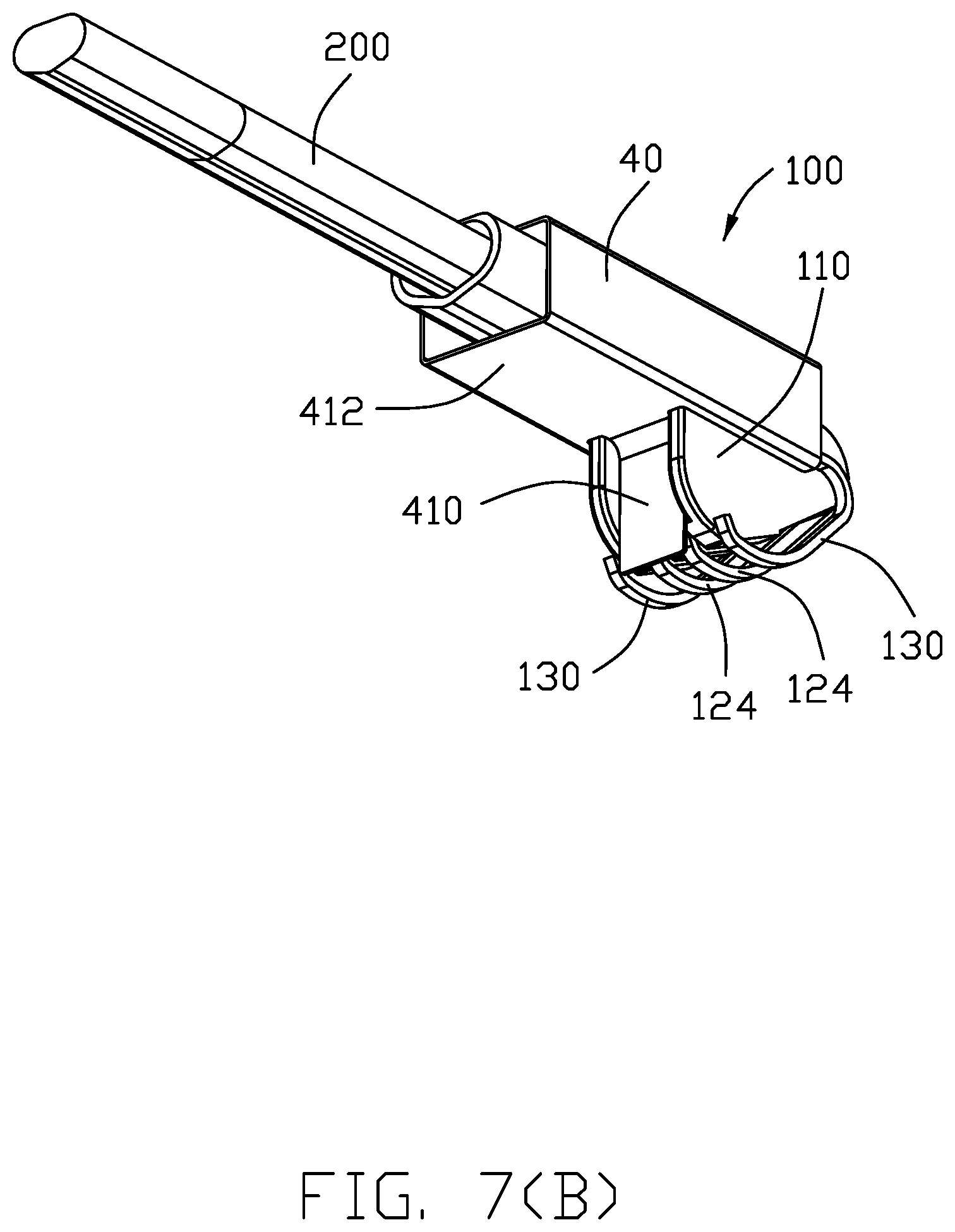
[0016] FIG. 7(B) is another perspective view of the cable assembly module of the electrical assembly of FIG. 7(A);
[0017] FIG. 7(C) is another perspective view of the cable assembly module of the electrical assembly of FIG. 7(A);
[0018] FIG. 8 is an exploded perspective view of the cable assembly module of the electrical assembly of FIG. 7(A);
[0019] FIG. 9(A) is a further exploded perspective view of the cable assembly module of the electrical assembly of FIG. 8;
[0020] FIG. 9(B) is another exploded perspective view of the cable assembly module of the electrical assembly of FIG. 9(A);
[0021] FIG. 10 is a perspective view of a cable and a pair of signal contacts of the cable assembly module of the electrical assembly of FIG. 9(A);
[0022] FIG. 11(A) is a perspective view of a second embodiment of an electrical cable assembly according to the invention;
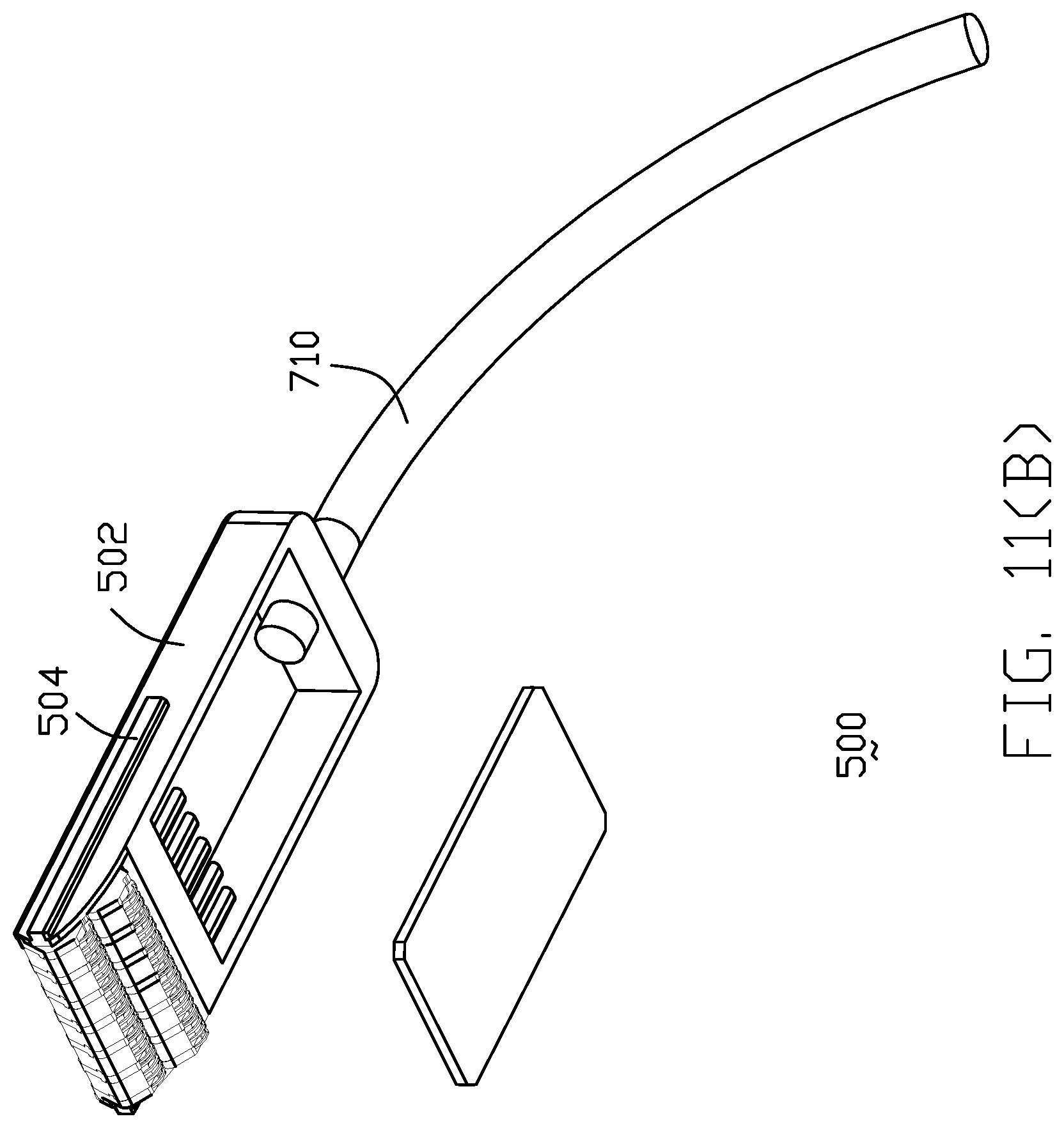
[0023] FIG. 11(B) is an exploded perspective view of the electrical cable assembly of FIG. 11(A);
[0024] FIG. 11(C) is an exploded perspective view of the electrical cable assembly of FIG. 11(A);
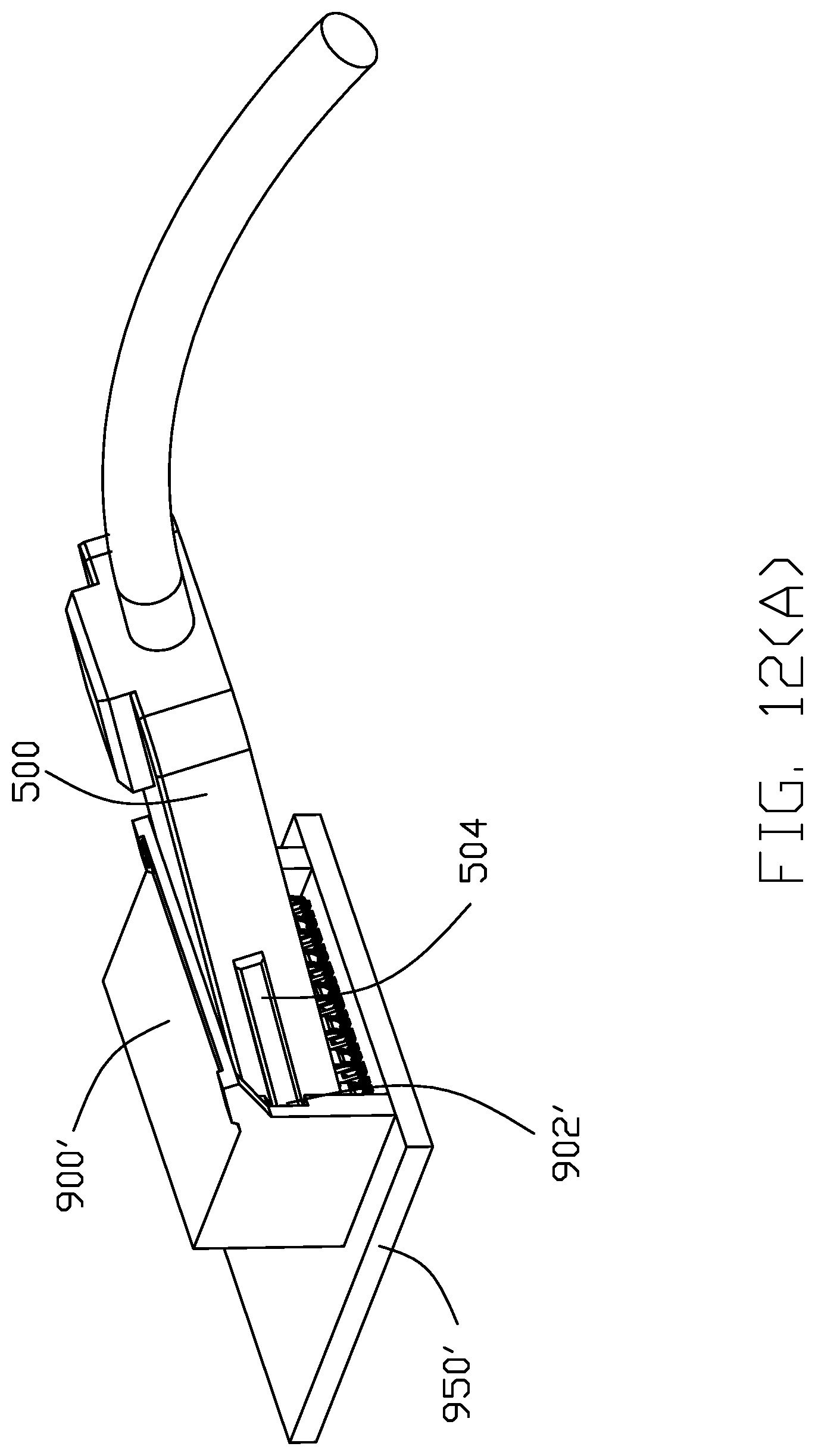
[0025] FIG. 12(A) is a perspective view of the electrical cable assembly of FIG. 11(A) received within a retainer mounted upon a printed circuit board;
[0026] FIG. 12(B) is an exploded perspective view of the electrical cable assembly and the retainer mounted upon a printed circuit board of FIG. 12(A);
[0027] FIG. 12(C) is a perspective view of the electrical cable assembly received within a retainer mounted upon a printed circuit board of FIG. 12(A) with a case of the electrical cable assembly being removed;
[0028] FIG. 13 is an elevational view of the electrical cable assembly and the retainer on the printed circuit board of FIG. 12(C);
[0029] FIG. 14 is a cross-sectional view of the electrical cable assembly and the retainer on the printed circuit board of FIG. 13;
[0030] FIG. 15(A) is a perspective view of cable modules of the electrical cable assembly of FIG. 11(A);
[0031] FIG. 15(B) is another perspective view of the cable modules of the electrical cable assembly of FIG. 15(A);
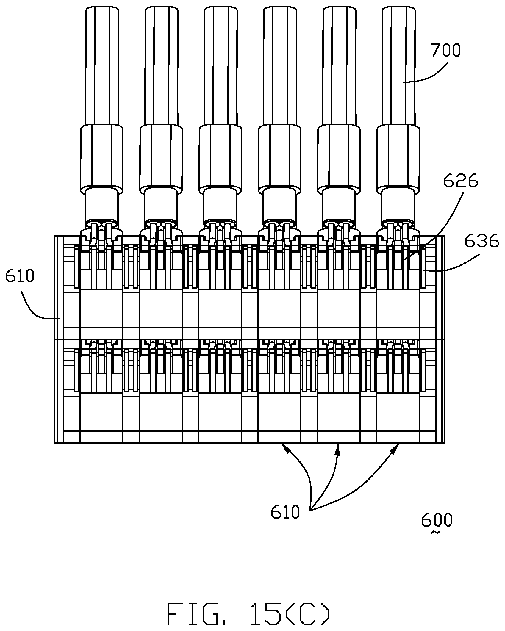
[0032] FIG. 15(C) is a top view of the cable modules of the electrical cable assembly of FIG. 15(A);
[0033] FIG. 16 is a top view of a printed circuit board on which the retainer of FIG. 13 is mounted;
[0034] FIG. 17(A) is a perspective view of the single cable module of the electrical cable assembly of FIG. 15(A);
[0035] FIG. 17(B) is another perspective view of the single cable module of the electrical cable assembly of the electrical assembly of FIG. 17(A);
[0036] FIG. 17(C) is another perspective view of the single cable module of the electrical cable assembly of FIG. 17(A);
[0037] FIG. 17(D) is another embodiment perspective view of the single cable module of the electrical cable assembly of FIG. 15(A);
[0038] FIG. 18(A) is an exploded perspective view of the single cable module of the electrical cable assembly of FIG. 17(A);
[0039] FIG. 18(B) is another exploded perspective view of the single cable module of the electrical cable assembly of FIG. 18(A);
[0040] FIG. 19(A) is a further exploded perspective view of a portion of the unit of the single cable module of the electrical cable assembly of FIG. 18(A);
[0041] FIG. 19(B) is another exploded perspective view of the portion the unit of the single cable module of the electrical cable assembly of FIG. 19(A);
[0042] FIG. 20(A) is an exploded perspective view of the portion of the unit of the single cable module of the electrical cable assembly of FIG. 19(A) wherein the signal contacts are integrally formed within the insulator;
[0043] FIG. 20(B) is another exploded perspective view of the portion of the unit of the single cable module of the electrical cable assembly of 20(A);
[0044] FIG. 21(A) is a perspective view of a first embodiment of a housing units and corresponding grounding contact carriers integrally formed together of the electrical cable assembly of FIG. 11(A);
[0045] FIG. 21(B) is another perspective view of the housing units and the corresponding grounding contact carriers of the electrical cable assembly of FIG. 21(A);
[0046] FIG. 22(A) is an exploded perspective view of the housing units and the corresponding grounding contact carriers of the electrical cable assembly of FIG. 21(A);
[0047] FIG. 22(B) is another exploded perspective view of the housing units and the corresponding grounding contact carriers of the electrical cable assembly of FIG. 22(A);
[0048] FIG. 23 is a perspective view of the grounding contact carrier of FIG. 22(A);
[0049] FIG. 24(A) is a perspective view of the housing units of FIG. 22(A);
[0050] FIG. 24(B) is a top view of the housing units of FIG. 24(A);
[0051] FIG. 25(A) is a perspective view of a second embodiment of the cable modules of the electrical cable assembly of FIG. 11(A);
[0052] FIG. 25(B) is another perspective view of the cable modules of electrical cable assembly of FIG. 25(A);
[0053] FIG. 26(A) is an exploded perspective view of the cable modules of electrical cable assembly of FIG. 25(A);
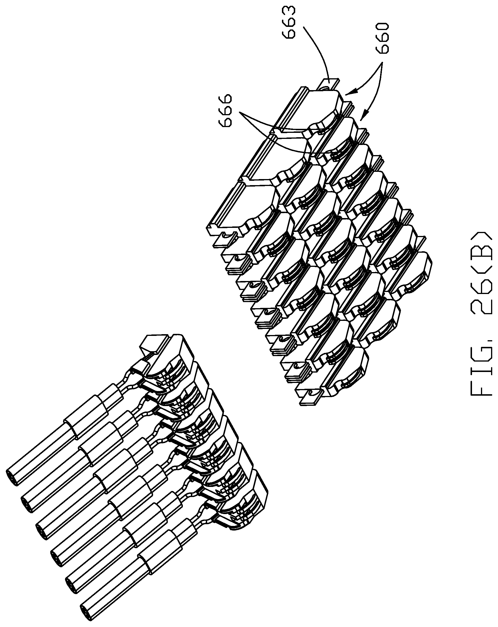
[0054] FIG. 26(B) is another exploded perspective view of the cable modules of the electrical cable assembly of FIG. 26(A);
[0055] FIG. 27(A) is an explode perspective view of the housing units and the corresponding grounding contact carriers of the cable modules of the electrical cable assembly of FIG. 26(A);
[0056] FIG. 27(B) is another exploded perspective view of the housing and the corresponding grounding contact carriers of the cable modules of the electrical cable assembly of FIG. 27(A);
[0057] FIG. 28 is a perspective view of the grounding contact carrier of the cable module of the electrical cable assembly of FIG. 27(A); and
[0058] FIG. 29 is a bottom view of the housing units and the grounding contact carriers of the cable module of the electrical cable assembly of FIG. 27(A).
DETAILED DESCRIPTION OF THE PREFERRED EMBODIMENT
[0059] Referring to FIGS. 1-10, a first embodiment of this invention comprises two rows of cable assembly modules 100 are arranged together to be commonly received, in an oblique manner, within a retainer 900 mounted upon a printed circuit board 800 on which the circuit pads 802 are formed. The retainer 900 comprises an upper inclined wall 901, and a lower inclined wall 903 spaced apart from and parallel to the upper inclined wall 91, and an inclined channel or entrance 902 formed in the oblique direction therebetween for the cable assembly modules 100 being entered into the retainer to mate with the circuit pads 802.
[0060] Each cable assembly module 100 includes a front mating member 110 having a wedged cross-section thereof, and a rear cable 200 linked behind the front mating member 110 and having a pair of signal wires 210. A pair of signal contacts 120 are retained upon the front mating member 10. Each signal contact 120 has a middle retaining section 122 grasping the front mating member 110, a front mating section 124 spaced from the mating member 110 in a deflectable manner, and a rear connecting section 126 mechanically and electrically connected to an inner conductor (not shown) of the signal wire 210 and spaced from the front mating member 110 in a deflectable manner. The front mating member 110 forms a pair of grooves 112 to receive front ends of the mating sections 124 of the pair of signal contacts 120 to prevent mechanical stubbing of the deflectable mating sections 124. A pair of grounding contacts 130 are located by two sides of the pair of signal contacts 120 are mechanically and electrically connected to the inner ground shell 300, and located by two sides of the pair of signal contacts 120 in the transverse direction. The front mating sections 124 are adapted for being directly mated with circuit pads 802 of a printed circuit board disposed in a plane, and the rear cable 200 extends along a direction inclined with the plane.
[0061] Each cable assembly module 100 further comprises a shielding shell forms a dividing wall 410 so as to perform shielding effect between the front mating member 110 of one cable assembly module 100 in a front row and that of another cable assembly module 100 in a rear row which are densely arranged with each other in a front-to-back direction. The shielding shell comprises an inner shielding shell 300 enclosing a front portion of the rear cable 200. The rear cable 200 further comprises a grounding/drain wire 220 electrically connected with the inner shielding shell 300. In this embodiment, the inner shielding shell 300 is a tubular metallic shell mechanically connected to the grounding wire 220 of the cable 200, and includes a platform 302 on which the mating member 110 is seated. The grounding contacts 130 are mechanically and electrically connected to the inner ground shell 300, and located by two sides of the pair of signal contacts 120 in the transverse direction.
[0062] The shielding shell comprises an outer shielding shell 400 enclosing and electrically connected with the inner shielding shell 300. The outer shielding shell 400 is electrically connected with the pair of the grounding contacts 130. In this embodiment, the outer shielding shell 400 is a tubular metallic outer wrap-around shell 400. The dividing wall 410 unitarily formed on the outer shielding shell, and split from a bottom wall 412 of the wrap-around shell 400 to form an opening 414 in front of the dividing wall 410. The front mating member 110 downwardly extends through the opening 414 to allow the front mating sections 124 of the signal contacts 120 to be seated upon the corresponding circuit pads 802 for connection.
[0063] Understandably, the retainer 900 may form the inclined channel or entrance 902 to regulate the corresponding cable assembly module 100 in position. A supporting plate 904 is detachably attached to the retainer 900 to complete the inclined channel or entrance 902 after the cable assembly modules 100 are installed within the retainer 900 in an oblique manner. The lower inclined wall 903 is formed on a top surface of the supporting plate 904. The lateral sides of the outer shielding shell 400 may form the corresponding interengaging structures, e.g. the tenon and the mortise, so as to allow the neighboring cable assembly modules 100 to be retain together as one piece along one row.
[0064] In this embodiment, only 2.times.2 cable assembly modules 100 are exemplified. Anyhow, the N.times.M matrix arrangement of the cable assembly modules 100 can be implemented. In this embodiment, the inner shielding shell 300 and the outer shielding shell 400 commonly forming the shielding shell structure, are discrete from each other. Alternately, a unified structure may be feasible. In this embodiment, the pair of grounding contacts 220 are discrete from the inner ground shell 300. Alternately, the pair of grounding contacts may be unitarily formed upon the inner shielding shell 300.
[0065] In this embodiment, the dividing wall 410 is located between the neighboring cable assembly module 100 in the front-to-back direction. Alternately, the dividing wall 410 may be located between the neighboring cable assembly module 100 in the transverse direction perpendicular to both the front-to-back direction and the vertical direction. Notably, in this embodiment, the rear side of the mating member 110 is recessed to receive the corresponding dividing wall 410 therein.
[0066] Referring to FIGS. 11(A)-29, a second embodiment electrical cable assembly 500 of this invention includes a case 502 enclosing two sets of cable modules 600 arranged in two rows along the transverse direction X. Each set of cable modules 600 includes a plurality of units 610 side by side arranged with one another along the row direction, i.e., the transverse direction. Each unit 610 includes a signal contact part 620 and a grounding contact part 630. The signal contact part 620 includes an insulator 622 or inner member integrally formed with a pair of signal contacts 624 via an insert-molding process. The signal contact 624 includes a deflectable contacting section 626 exposed upon a bottom side of the insulator 622, and a connecting section 628 exposed upon a top side of the insulator 622. The grounding contact part 630 includes an insulative housing unit 632 or outer member integrally formed with a U-shaped grounding contact 634. The grounding contact 634 includes a pair of deflectable contacting sections 636 exposed upon a bottom side of the housing unit 632 and a connecting section 638 exposed upon a top side of the housing unit 632. The housing unit 632 or outer member comprises a first side wall 6321, a second side wall 6322 spaced apart from and parallel to the first side wall 6321, a connecting wall 6323 connected therebetween, and a cavity or receiving space 637 formed by the first side wall 6321, the second wall 6322 and the connecting wall 6323. 12. One of the grounding contacts 634 is molded in the first side wall 6321, and the other one of the grounding contacts 634 is molded in the second side wall 6322. Notably, the insulator 622 is forwardly, along the front-to-back direction Y, inserted into and received within a cavity or receiving space 637 of the housing unit 632. Each unit 610 further includes a cable 700 composed of a differential pair of wires 702 and a drain wire or grounding wire 704 wherein the differential pair of wires 702 are soldered on the connecting sections 628 of the signal contact 624, and the drain wire 704 is soldered on the connecting section 638 of the grounding contact 634. A pair of grounding contacts 634 comprises a bridge member 6340 connected therebetween. The bridge is molded in the connecting wall 6323. The grounding wire 704 is mechanically and electrically connected to the bridge member 6340. The insulator 622 forms a pair of sliding grooves 623 receiving the corresponding sliding rails 631 of the housing unit 632. In this embodiment, the housing units 632 are unitarily formed together as one piece. Understandably, the housing units 632 of the grounding contact parts 630 in the same set of cable module 600 are unified together as one piece for not only reinforcement but also unification. In addition, the U-shaped configuration of the grounding contact 634 not only efficiently shield the corresponding differential pair signal contacts 642 therein but also reinforce the structure of the unified housing 635. The cables 700 of all units 610 are joined together as the round cable 710 to extend out of a rear end of the case 502. Referring to FIG. 17(D), the cable 700 is omitted drain wire and the pair of grounding contacts 634 are omitted bridge member.
[0067] Referring to FIGS. 11-29, the grounding contact part 630 is made by providing a plurality of grounding contact carriers 633 side by side intimately arranged with one another along the transverse direction wherein each contact carrier 633 unitarily includes three grounding contacts 634 along the front-to-back direction. The housing units 632 are integrally formed on the grounding contact carriers 633 via an insert-molding process to have the housing units 632 in the same row along the transverse direction are joined with one another as one piece unified housing 635. The three housings 635 each made by the unified housing units 632, are separated from one another by severing the portions A, B, C and D of the grounding contact carrier 633. The uniformed housing 635 include a pair of guiding rails 640 on opposite external side faces so as to be received within the corresponding guiding grooves (not shown) in the interior surfaces of the case 502.
[0068] In this embodiment, the electrical cable assembly 500 is inserted into a space 602 of the retainer 900' which is mounted upon the printed circuit board 950'. Two rows of circuit pads 952' are formed on the printed circuit board 950' under the space 602. The case 502 of the electrical cable assembly 500 further forms a pair of guiding protrusions 504 on two opposite exterior surfaces to be received within the corresponding guiding grooves 902' formed in an interior surfaces of the retainer 900' wherein the guiding groove 902' extends obliquely. Understandably, because the case 502 is assembled into the retainer 400 in the oblique direction, the contacting sections 626 and 636 are deflected in the vertical direction Z to efficiently mechanically and electrically connect to the corresponding circuit pads 952', respectively, when the case 502 reaches the final position. Understandably, the case 502 and the retainer 900' may form some retention mechanism for reliably maintaining the case 502 in position within retainer 900'.
[0069] The feature of the invention is to provide two rows of the cable modules 600 with the corresponding two rows of deflectable contacting sections 626, 636 which are deflected to connect the corresponding circuit pads 952' at the same time, wherein the mating face of the case 502 commonly defined by the bottom sides of the units 610 of both two sets of cable modules 600 is oblique to the primary plane of the case and located at the front end of the electrical cable assembly 500. In other words, the oblique arrangement for plural rows of cable modules while still keeping the corresponding contacting sections of all cable modules in the same level, is the feature of the instant invention.
[0070] FIGS. 25(A)-29 show another embodiment of the grounding contact unit 660. Each grounding contact part 660 includes a pair of grounding contacts 664 insert-molded within two opposite side walls of an insulative housing unit 662. The grounding contact 664 includes a deflectable contacting section 666 on a bottom side of the insulator 662 for connecting to the corresponding circuit pad on the printed circuit board. Understandably, in this embodiment the contact carrier 663 lies in a vertical plane so as not to form the corresponding connecting section for soldering to the corresponding drain wire. Anyhow, the grounding contact may be provided with the horizontal connecting section by the contact carrier 663 for soldering to the corresponding drain wire, if necessary. Similar to the first embodiment, the housing units 662 in the same row along the transverse direction are joined together to form a unified housing 665.
* * * * *
D00000
D00001
D00002
D00003
D00004
D00005
D00006
D00007
D00008
D00009
D00010
D00011
D00012

D00013

D00014

D00015

D00016

D00017
D00018

D00019
D00020

D00021

D00022

D00023

D00024

D00025

D00026
D00027

D00028

D00029

D00030

D00031

D00032

D00033

D00034

D00035

D00036

D00037

D00038

D00039

D00040

D00041

D00042

D00043

D00044

D00045

D00046

D00047

D00048
D00049

D00050

D00051

D00052

XML
uspto.report is an independent third-party trademark research tool that is not affiliated, endorsed, or sponsored by the United States Patent and Trademark Office (USPTO) or any other governmental organization. The information provided by uspto.report is based on publicly available data at the time of writing and is intended for informational purposes only.
While we strive to provide accurate and up-to-date information, we do not guarantee the accuracy, completeness, reliability, or suitability of the information displayed on this site. The use of this site is at your own risk. Any reliance you place on such information is therefore strictly at your own risk.
All official trademark data, including owner information, should be verified by visiting the official USPTO website at www.uspto.gov. This site is not intended to replace professional legal advice and should not be used as a substitute for consulting with a legal professional who is knowledgeable about trademark law.