Systems And Methods Having An Optical Magnetometer Array With Beam Splitters
Mohseni; Hooman
U.S. patent application number 16/984752 was filed with the patent office on 2021-02-11 for systems and methods having an optical magnetometer array with beam splitters. The applicant listed for this patent is HI LLC. Invention is credited to Hooman Mohseni.
| Application Number | 20210041513 16/984752 |
| Document ID | / |
| Family ID | 1000005004248 |
| Filed Date | 2021-02-11 |


| United States Patent Application | 20210041513 |
| Kind Code | A1 |
| Mohseni; Hooman | February 11, 2021 |
SYSTEMS AND METHODS HAVING AN OPTICAL MAGNETOMETER ARRAY WITH BEAM SPLITTERS
Abstract
An array of optically pumped magnetometers includes an array of vapor cells; and an array of beam splitters. The array of beam splitters is arranged into columns, including a first column, and rows. Each row and each column includes at least two of the beam splitters. The array of beam splitters is configured to receive light into the first column of the array and to distribute that light from the first column into each of the rows and to distribute the light from each of the rows into a plurality of individual light beams directed toward the vapor cells.
| Inventors: | Mohseni; Hooman; (Wilmette, IL) | ||||||||||
| Applicant: |
|
||||||||||
|---|---|---|---|---|---|---|---|---|---|---|---|
| Family ID: | 1000005004248 | ||||||||||
| Appl. No.: | 16/984752 | ||||||||||
| Filed: | August 4, 2020 |
Related U.S. Patent Documents
| Application Number | Filing Date | Patent Number | ||
|---|---|---|---|---|
| 62896929 | Sep 6, 2019 | |||
| 62883406 | Aug 6, 2019 | |||
| Current U.S. Class: | 1/1 |
| Current CPC Class: | G01R 33/26 20130101 |
| International Class: | G01R 33/26 20060101 G01R033/26 |
Claims
1. An array of optically pumped magnetometers, comprising: an array of vapor cells; and an array of beam splitters, wherein the array of beam splitters is arranged into a plurality of columns, including a first column, and a plurality of rows, wherein each row and each column comprises at least two of the beam splitters, wherein the array of beam splitters is configured to receive light into the first column of the array and to distribute that light from the first column into each of the plurality of rows and to distribute the light from each of the rows into a plurality of individual light beams directed toward the vapor cells.
2. The array of optically pumped magnetometers of claim 1, wherein the array of vapor cells is an N.times.M array and the array of beam splitters is an (N+1).times.M array, wherein N and M are integers greater than one.
3. The array of optically pumped magnetometers of claim 2, wherein the array of beam splitters is configured to generate N.times.M beams of light.
4. The array of optically pumped magnetometers of claim 3, wherein the N.times.M beams of light have intensities that differ by no more than 5% from each other.
5. The array of optically pumped magnetometers of claim 1, wherein the first column has M of the beam splitters and the m-th one of the beam splitters in the first column has a reflectivity of 1/(M-m+1), wherein M is an integer greater than one and m is an integer ranging from 1 to M.
6. The array of optically pumped magnetometers of claim 1, wherein at least one row has a one of the beam splitters from the first column followed by N of the beam splitters after, wherein the n-th one of the N beam splitters has a reflectivity of 1/(N-n+1), wherein N is an integer greater than one and n is an integer ranging from 1 to N.
7. The array of optically pumped magnetometers of claim 1, further comprising a quarter waveplate disposed between the array of beam splitters and the array of vapor cells.
8. The array of optically pumped magnetometers of claim 1, further comprising a light source configured and arranged to direct light into the first column of the array of beam splitters.
9. The array of optically pumped magnetometers of claim 1, further comprising a reference detector configured to receive light that has passed through the beam splitters of the first column.
10. The array of optically pumped magnetometers of claim 1, wherein the beam splitters are polarizing beam splitters.
11. The array of optically pumped magnetometers of claim 10, further comprising waveplates disposed between adjacent ones of the polarizing beam splitters to rotate a polarization of a light beam exiting one of the polarizing beam splitters prior to entering another one of the polarizing beam splitters.
12. The array of optically pumped magnetometers of claim 1, wherein the beam splitters are bonded together into a single block using optical adhesive.
13. A magnetic field measurement system, comprising: an array of vapor cells; an array of light detectors configured to receive light passing through the vapor cells; and an array of beam splitters, wherein the array of beam splitters is arranged into a plurality of columns, including a first column, and a plurality of rows, wherein each row and each column comprises at least two of the beam splitters, wherein the array of beam splitters is configured to receive light into the first column of the array and to distribute that light from the first column into each of the plurality of rows and to distribute the light from each of the rows into a plurality of individual light beams directed toward the vapor cells.
14. The magnetic field measurement system of claim 13, further comprising at least one magnetic field generator disposed around at least one of the vapor cells to generate a magnetic field in the vapor cell.
15. The magnetic field measurement system of claim 13, further comprising a light source configured and arranged to direct light into the first column of the array of beam splitters.
16. The magnetic field measurement system of claim 15, further comprising a computing device coupled to the array of light detectors and the light source.
17. The magnetic field measurement system of claim 13, further comprising a wearable article within which the array of vapor cells, array of light detectors and array of beam splitters are disposed.
18. The magnetic field measurement system of claim 17, further comprising a light source disposed in the wearable article and configured and arranged to direct light into the first column of the array of beam splitters.
19. The magnetic field measurement system of claim 13, wherein the first column has M of the beam splitters and the m-th one of the beam splitters in the first column has a reflectivity of 1/(M-m+1), wherein M is an integer greater than one and m is an integer ranging from 1 to M.
20. The magnetic field measurement system of claim 13, wherein at least one row has a one of the beam splitters from the first column followed by N of the beam splitters after, wherein the n-th one of the N beam splitters has a reflectivity of 1/(N-n+1), wherein N is an integer greater than one and n is an integer ranging from 1 to N.
Description
CROSS-REFERENCE TO RELATED APPLICATIONS
[0001] This application claims the benefit of U.S. Provisional Patent Application Ser. Nos. 62/883,406, filed Aug. 6, 2019, and 62/896,929, filed Sep. 6, 2019, both of which are incorporated herein by reference in their entireties.
FIELD
[0002] The present disclosure is directed to the area of magnetic field measurement systems including systems for magnetoencephalography (MEG). The present disclosure is also directed to methods and systems having an array of optically pumped magnetometers (OPM) and an array of beam splitters for applications such as high spatial resolution MEG.
BACKGROUND
[0003] In the nervous system, neurons propagate signals via action potentials. These are brief electric currents which flow down the length of a neuron causing chemical transmitters to be released at a synapse. The time-varying electrical currents within an ensemble of neurons generates a magnetic field. Magnetoencephalography (MEG), the measurement of magnetic fields generated by the brain, is one method for observing these neural signals.
[0004] Existing technology for measuring MEG typically utilizes superconducting quantum interference devices (SQUIDs) or collections of discrete optically pumped magnetometers (OPMs). SQUIDs require cryogenic cooling, which is bulky, expensive, requires a lot of maintenance. These requirements preclude their application to mobile or wearable devices.
[0005] An alternative to an array of SQUIDs is an array of OPMs. For MEG and other applications, the array of OPMS may have a large number of OPM sensors that are tightly packed. Such dense arrays can produce a high resolution spatial mapping of the magnetic field, and at a very high sensitivity level. Such OPMs sensors can be used for a wide range of applications, including sensing magnetic field generated by neural activities, similar to MEG systems.
BRIEF SUMMARY
[0006] One embodiment is an array of optically pumped magnetometers that includes an array of vapor cells; and an array of beam splitters. The array of beam splitters is arranged into columns, including a first column, and rows. Each row and each column includes at least two of the beam splitters. The array of beam splitters is configured to receive light into the first column of the array and to distribute that light from the first column into each of the rows and to distribute the light from each of the rows into a plurality of individual light beams directed toward the vapor cells.
[0007] In at least some embodiments, the array of vapor cells is an N.times.M array and the array of beam splitters is an (N+1).times.M array, wherein N and M are integers greater than one. In at least some embodiments, the array of beam splitters is configured to generate N.times.M beams of light. In at least some embodiments, the N.times.M beams of light have intensities that differ by no more than 5% from each other.
[0008] In at least some embodiments, the first column has M of the beam splitters and the m-th one of the beam splitters in the first column has a reflectivity of 1/(M-m+1), wherein M is an integer greater than one and m is an integer ranging from 1 to M. In at least some embodiments, at least one row has a one of the beam splitters from the first column followed by N of the beam splitters after, wherein the n-th one of the N beam splitters has a reflectivity of 1/(N-n+1), wherein N is an integer greater than one and n is an integer ranging from 1 to N.
[0009] In at least some embodiments, the array of optically pumped magnetometers further includes a quarter waveplate disposed between the array of beam splitters and the array of vapor cells. In at least some embodiments, the array of optically pumped magnetometers further includes a light source configured and arranged to direct light into the first column of the array of beam splitters. In at least some embodiments, the array of optically pumped magnetometers further includes a reference detector configured to receive light that has passed through the beam splitters of the first column.
[0010] In at least some embodiments, the beam splitters are polarizing beam splitters. In at least some embodiments, the array of optically pumped magnetometers further includes waveplates disposed between adjacent ones of the polarizing beam splitters to rotate a polarization of a light beam exiting one of the polarizing beam splitters prior to entering another one of the polarizing beam splitters.
[0011] In at least some embodiments, the beam splitters are bonded together into a single block using optical adhesive.
[0012] Another embodiment is a magnetic field measurement system that includes an array of vapor cells; an array of light detectors configured to receive light passing through the vapor cells; and an array of beam splitters. The array of beam splitters is arranged into columns, including a first column, and rows. Each row and each column includes at least two of the beam splitters. The array of beam splitters is configured to receive light into the first column of the array and to distribute that light from the first column into each of the plurality of rows and to distribute the light from each of the rows into a plurality of individual light beams directed toward the vapor cells.
[0013] In at least some embodiments, the magnetic field measurement system further includes at least one magnetic field generator disposed around at least one of the vapor cells to generate a magnetic field in the vapor cell. In at least some embodiments, the magnetic field measurement system further includes a light source configured and arranged to direct light into the first column of the array of beam splitters. In at least some embodiments, the magnetic field measurement system further includes a computing device coupled to the array of light detectors and the light source.
[0014] In at least some embodiments, the magnetic field measurement system further includes a wearable article within which the array of vapor cells, array of light detectors and array of beam splitters are disposed. In at least some embodiments, the magnetic field measurement system further includes a light source disposed in the wearable article and configured and arranged to direct light into the first column of the array of beam splitters.
[0015] In at least some embodiments, the first column has M of the beam splitters and the m-th one of the beam splitters in the first column has a reflectivity of 1/(M-m+1), wherein M is an integer greater than one and m is an integer ranging from 1 to M. In at least some embodiments, at least one row has a one of the beam splitters from the first column followed by N of the beam splitters after, wherein the n-th one of the N beam splitters has a reflectivity of 1/(N-n+1), wherein N is an integer greater than one and n is an integer ranging from 1 to N.
BRIEF DESCRIPTION OF THE DRAWINGS
[0016] Non-limiting and non-exhaustive embodiments of the present invention are described with reference to the following drawings. In the drawings, like reference numerals refer to like parts throughout the various figures unless otherwise specified.
[0017] For a better understanding of the present invention, reference will be made to the following Detailed Description, which is to be read in association with the accompanying drawings, wherein:
[0018] FIG. 1A is a schematic block diagram of one embodiment of a magnetic field measurement system, according to the invention;
[0019] FIG. 1B is a schematic block diagram of one embodiment of a magnetometer, according to the invention;
[0020] FIG. 2 shows a magnetic spectrum with lines indicating dynamic ranges of magnetometers operating in different modes;
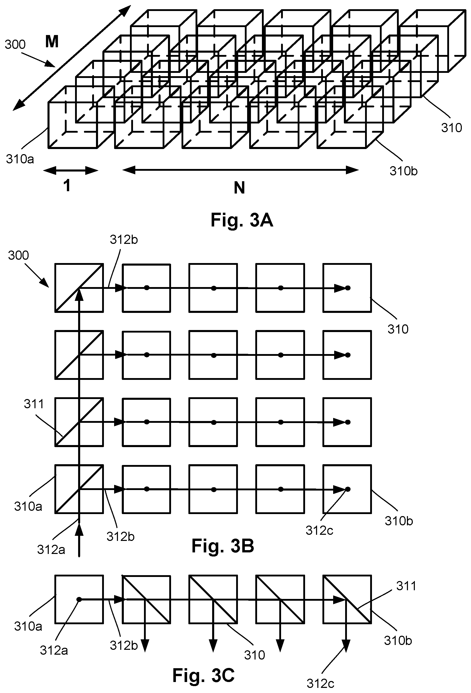
[0021] FIG. 3A is a perspective view of one embodiment of an array of beam splitters for use with an array of magnetometers, according to the invention;
[0022] FIG. 3B is a top view of the array of beam splitters of FIG. 3A, according to the invention;
[0023] FIG. 3C is a front view of one row of the array of beam splitters of FIG. 3A, according to the invention;
[0024] FIG. 4 is a perspective view of one embodiment of an array of magnetometers including the array of beam splitters of FIG. 3A, according to the invention;
[0025] FIG. 5 is a top view of another embodiment of an array of beam splitters for use with an array of magnetometers, according to the invention;
[0026] FIG. 6 is a top view of a third embodiment of an array of beam splitters for use with an array of magnetometers, according to the invention;
[0027] FIG. 7A is a perspective view of a prism for use in an array of beam splitters, according to the invention;
[0028] FIG. 7B is a perspective view of several of the prisms coated for use in an array of beam splitters, according to the invention;
[0029] FIG. 7C is a perspective view of an arrangement of different prisms for use in an array of beam splitters, according to the invention; and
[0030] FIG. 7D is a perspective view of an arrangement of different prisms bonded for use in an array of beam splitters, according to the invention.
DETAILED DESCRIPTION
[0031] The present disclosure is directed to the area of magnetic field measurement systems including systems for magnetoencephalography (MEG). The present disclosure is also directed to methods and systems having an array of optically pumped magnetometers (OPM) and an array of beam splitters for applications such as high spatial resolution MEG.
[0032] Herein the terms "ambient background magnetic field" and "background magnetic field" are interchangeable and used to identify the magnetic field or fields associated with sources other than the magnetic field measurement system and the magnetic field sources of interest, such as biological source(s) (for example, neural signals from a user's brain) or non-biological source(s) of interest. The terms can include, for example, the Earth's magnetic field, as well as magnetic fields from magnets, electromagnets, electrical devices, and other signal or field generators in the environment, except for the magnetic field generator(s) that are part of the magnetic field measurement system.
[0033] The terms "gas cell", "vapor cell", and "vapor gas cell" are used interchangeably herein. Below, a gas cell containing alkali metal vapor is described, but it will be recognized that other gas cells can contain different gases or vapors for operation.
[0034] The methods and systems are described herein using optically pumped magnetometers (OPMs). While there are many types of OPMs, in general magnetometers operate in two modalities: vector mode and scalar mode. In vector mode, the OPM can measure one, two, or all three vector components of the magnetic field; while in scalar mode the OPM can measure the total magnitude of the magnetic field.
[0035] Vector mode magnetometers measure a specific component of the magnetic field, such as the radial and tangential components of magnetic fields with respect the scalp of the human head. Vector mode OPMs often operate at zero-field and may utilize a spin exchange relaxation free (SERF) mode to reach femto-Tesla sensitivities. A SERF mode OPM is one example of a vector mode OPM, but other vector mode OPMs can be used at higher magnetic fields. These SERF mode magnetometers can have high sensitivity but may not function in the presence of magnetic fields higher than the linewidth of the magnetic resonance of the atoms of about 10 nT, which is much smaller than the magnetic field strength generated by the Earth.
[0036] Magnetometers operating in the scalar mode can measure the total magnitude of the magnetic field. (Magnetometers in the vector mode can also be used for magnitude measurements.) Scalar mode OPMs often have lower sensitivity than SERF mode OPMs and are capable of operating in higher magnetic field environments.
[0037] The magnetic field measurement systems, such as a biological signal detection system, described herein can be used to measure or observe electromagnetic signals generated by one or more magnetic field sources (for example, neural signals or other biological sources) of interest. The system can measure biologically generated magnetic fields and, at least in some embodiments, can measure biologically generated magnetic fields in an unshielded or partially shielded environment. Aspects of a magnetic field measurement system will be exemplified below using magnetic signals from the brain of a user; however, biological signals from other areas of the body, as well as non-biological signals, can be measured using the system. In at least some embodiments, the system can be a wearable MEG system that can be portable and used outside a magnetically shielded room.
[0038] A magnetic field measurement system, such as a biological signal detection system, can utilize one or more magnetic field sensors. Magnetometers will be used herein as an example of magnetic field sensors, but other magnetic field sensors may also be used in addition to, or as an alternative to, the magnetometers. FIG. 1A is a block diagram of components of one embodiment of a magnetic field measurement system 140 (such as a biological signal detection system.) The system 140 can include a computing device 150 or any other similar device that includes a processor 152, a memory 154, a display 156, an input device 158, one or more magnetometers 160 (for example, an array of magnetometers) which can be OPMs, one or more magnetic field generators 162, and, optionally, one or more other sensors 164 (e.g., non-magnetic field sensors). The system 140 and its use and operation will be described herein with respect to the measurement of neural signals arising from one or more magnetic field sources of interest in the brain of a user as an example. It will be understood, however, that the system can be adapted and used to measure signals from other magnetic field sources of interest including, but not limited to, other neural signals, other biological signals, as well as non-biological signals.
[0039] The computing device 150 can be a computer, tablet, mobile device, field programmable gate array (FPGA), microcontroller, or any other suitable device for processing information or instructions. The computing device 150 can be local to the user or can include components that are non-local to the user including one or both of the processor 152 or memory 154 (or portions thereof). For example, in at least some embodiments, the user may operate a terminal that is connected to a non-local computing device. In other embodiments, the memory 154 can be non-local to the user.
[0040] The computing device 150 can utilize any suitable processor 152 including one or more hardware processors that may be local to the user or non-local to the user or other components of the computing device. The processor 152 is configured to execute instructions stored in the memory 154.
[0041] Any suitable memory 154 can be used for the computing device 150. The memory 154 illustrates a type of computer-readable media, namely computer-readable storage media. Computer-readable storage media may include, but is not limited to, volatile, nonvolatile, non-transitory, removable, and non-removable media implemented in any method or technology for storage of information, such as computer readable instructions, data structures, program modules, or other data. Examples of computer-readable storage media include RAM, ROM, EEPROM, flash memory, or other memory technology, CD-ROM, digital versatile disks ("DVD") or other optical storage, magnetic cassettes, magnetic tape, magnetic disk storage or other magnetic storage devices, or any other medium which can be used to store the desired information and which can be accessed by a computing device.
[0042] Communication methods provide another type of computer readable media; namely communication media. Communication media typically embodies computer-readable instructions, data structures, program modules, or other data in a modulated data signal such as a carrier wave, data signal, or other transport mechanism and include any information delivery media. The terms "modulated data signal," and "carrier-wave signal" includes a signal that has one or more of its characteristics set or changed in such a manner as to encode information, instructions, data, and the like, in the signal. By way of example, communication media includes wired media such as twisted pair, coaxial cable, fiber optics, wave guides, and other wired media and wireless media such as acoustic, RF, infrared, and other wireless media.
[0043] The display 156 can be any suitable display device, such as a monitor, screen, or the like, and can include a printer. In some embodiments, the display is optional. In some embodiments, the display 156 may be integrated into a single unit with the computing device 150, such as a tablet, smart phone, or smart watch. In at least some embodiments, the display is not local to the user. The input device 158 can be, for example, a keyboard, mouse, touch screen, track ball, joystick, voice recognition system, or any combination thereof, or the like. In at least some embodiments, the input device is not local to the user.
[0044] The magnetic field generator(s) 162 can be, for example, Helmholtz coils, solenoid coils, planar coils, saddle coils, electromagnets, permanent magnets, or any other suitable arrangement for generating a magnetic field. As an example, the magnetic field generator 162 can include three orthogonal sets of coils to generate magnetic fields along three orthogonal axes. Other coil arrangement can also be used. The optional sensor(s) 164 can include, but are not limited to, one or more position sensors, orientation sensors, accelerometers, image recorders, or the like or any combination thereof.
[0045] The one or more magnetometers 160 can be any suitable magnetometer including, but not limited to, any suitable optically pumped magnetometer. Arrays of magnetometers are described in more detail herein. In at least some embodiments, at least one of the one or more magnetometers (or all of the magnetometers) of the system is arranged for operation in the SERF mode.
[0046] FIG. 1B is a schematic block diagram of one embodiment of a magnetometer 160 which includes a vapor cell 170 (also referred to as a "cell") such as an alkali metal vapor cell; a heating device 176 to heat the cell 170; a light source 172; and a detector 174. In addition, coils of a magnetic field generator 162 can be positioned around the vapor cell 170. The vapor cell 170 can include, for example, an alkali metal vapor (for example, rubidium in natural abundance, isotopically enriched rubidium, potassium, or cesium, or any other suitable alkali metal such as lithium, sodium, or francium) and, optionally, one, or both, of a quenching gas (for example, nitrogen) and a buffer gas (for example, nitrogen, helium, neon, or argon). In some embodiments, the vapor cell may include the alkali metal atoms in a prevaporized form prior to heating to generate the vapor.
[0047] The light source 172 can include, for example, a laser to, respectively, optically pump the alkali metal atoms and probe the vapor cell. The light source 172 may also include optics (such as lenses, waveplates, collimators, polarizers, and objects with reflective surfaces) for beam shaping and polarization control and for directing the light from the light source to the cell and detector. Examples of suitable light sources include, but are not limited to, a diode laser (such as a vertical-cavity surface-emitting laser (VCSEL), distributed Bragg reflector laser (DBR), or distributed feedback laser (DFB)), light-emitting diode (LED), lamp, or any other suitable light source. In some embodiments, the light source 172 may include two light sources: a pump light source and a probe light source.
[0048] The detector 174 can include, for example, an optical detector to measure the optical properties of the transmitted probe light field amplitude, phase, or polarization, as quantified through optical absorption and dispersion curves, spectrum, or polarization or the like or any combination thereof. Examples of suitable detectors include, but are not limited to, a photodiode, charge coupled device (CCD) array, CMOS array, camera, photodiode array, single photon avalanche diode (SPAD) array, avalanche photodiode (APD) array, or any other suitable optical sensor array that can measure the change in transmitted light at the optical wavelengths of interest.
[0049] FIG. 2 shows the magnetic spectrum from 1 fT to 100 .mu.T in magnetic field strength on a logarithmic scale. The magnitude of magnetic fields generated by the human brain are indicated by range 201 and the magnitude of the background ambient magnetic field, including the Earth's magnetic field, by range 202. The strength of the Earth's magnetic field covers a range as it depends on the position on the Earth as well as the materials of the surrounding environment where the magnetic field is measured. Range 210 indicates the approximate measurement range of a magnetometer (e.g., an OPM) operating in the SERF mode (e.g., a SERF magnetometer) and range 211 indicates the approximate measurement range of a magnetometer operating in a scalar mode (e.g., a scalar magnetometer.) Typically, a SERF magnetometer is more sensitive than a scalar magnetometer but many conventional SERF magnetometers typically only operate up to about 0 to 200 nT while the scalar magnetometer starts in the 10 to 100 fT range but extends above 10 to 100 .mu.T.
[0050] The systems and methods described herein will utilize OPMs, but it will be understood that other magnetometers can be used in addition to, or instead of, OPMs. In at least some embodiments, the OPMs utilize laser light for pumping and probing the vapor cell of the OPM. When an array of OPMs is used, the laser light is delivered to each OPM vapor cell in the array. Individual lasers could be used for the individual OPMs, but such an arrangement is inefficient and may result in substantial noise as the noise in each laser can vary independently of the others. One conventional method for providing laser light to multiple vapor cells utilizes fiber splitters which divide the optical beam of one or more lasers for delivery into multiple optical fibers. The optical fibers deliver the laser light to the individual vapor cells of the OPMs. A challenge with this approach is the large number of fibers involved, as well as the noise generated due to polarization shifting arising from mechanical deformation of the fibers (even from polarization maintaining fibers).
[0051] Another conventional approach divides the beam from one laser into four different sensing regions within a sensor head using a diffractive optical element. However, this arrangement has a relatively large distance between the diffraction element and a lens to collimate the laser light because the deflection angle of the diffraction element cannot be very large. In addition, the numerical aperture (NA) of the lens also limits this distance. In addition, this approach may not be scalable for systems with significantly more than four channels.
[0052] In contrast to these conventional arrangements, in at least some embodiments, a system or method includes splitting the beam(s) of one or more surface emitting lasers using an array of beam splitters. In at least some embodiments, the array of beam splitters forms a two-dimensional grid.
[0053] FIGS. 3A-3C illustrate one embodiment of an array 300 of beam splitters 310 (which may be in the form of cubes or any other suitable shape) for use with an N.times.M array of OPMs or other magnetometers. FIG. 3B is a top view of the array 300 and FIG. 3C is a front view of one row of the beam splitters 310. There are (N+1).times.M beam splitters 310. In at least some embodiments, these beam splitters 310 are not polarizing beam splitters. In this array, one column of M beam splitters 310a (the leftmost column in the illustrated embodiment) are initial beam splitters that, as illustrated in FIG. 3B, divide the input beam 312a from the light source 472 (see, FIG. 4) into M beams 312b with each beam then proceeding down a row of the array 300. In at least some embodiments, the beam splitters 310a are arranged to produce the M beams 312b with equal or nearly equal intensity (for example, within 1, 5, or 10% of each other).
[0054] The remainder (an N.times.M array) of the beam splitters 310b divide the M beams 312b into N.times.M beams 312c (indicated by dots in FIG. 3B). In at least some embodiments, the resulting N.times.M beams 312c will have equal or nearly equal intensity (for example, within 1, 5, or 10% of each other).
[0055] The intensity of the beams 312b, 312c that exit each of the beam splitters 310 can be tailored through the construction of the beam splitter. In at least some embodiments, the use of one or more coatings (for example, adhesive, metallic, or dichroic coatings) on each beam splitter can be used to select the amount of light transmitted through the beam splitter 310 and the amount of light reflected by the interface 311 within the beam splitter 310. Other methods or mechanism (including polarization, as described below) can be used to select the amounts of transmission and reflection of the light by the individual beam splitters 310.
[0056] In at least some embodiments, the transmission and reflection of each of these beam splitters 310a, 310b is a function of their location in the array and is selected so that the resulting beams are equal, or approximately equal, in intensity. (Although a uniform beam intensity is often useful, in other embodiments, the beams 312b or the beams 312c may have different intensities and may have non-uniform beam splitting. For example, some embodiments may benefit from some vapor cells receiving higher intensity light than others to enhance dynamic range or the like.) In embodiments where the intensities are equal or approximately equal, the m-th beam splitter 310a of the first 1.times.M array has a reflectivity of 1/(M-m+1). Thus, the reflectivity of the first beam splitter 310a is 1/M, the second beam splitter is 1/(M-1), the third beam splitter is 1/(M-2), and so forth. The transmission for the m-th beam splitter 310a is 1-1/(M-m+1). This arrangement leads to beams 312b each having a relatively equal value of reflected light from the array with each beam having ideally 1/M of the input laser power.
[0057] Each of the beams 312b go through a similar reflection and transmission process along one of the rows of the array of N.times.M beam splitters 310b. In each row, the n-th beam splitter 310b (excluding the first beam splitter from this count) of the row has a reflectivity of 1/(N-n+1). The transmission for the n-th beam splitter 310b is 1-1/(N-n+1). This arrangement produces an array of N.times.M beams 312c with almost equal power, each approximately 1/NM of the original laser power. (For instances in which N=M, the result is N.sup.2 beams with each beam having approximately 1/N.sup.2 of the original laser power.) The orientation of the beam splitters 310b in the N.times.M array is such that each of these beams 312c will propagate perpendicular to the plane of the array 300, as shown in FIG. 3C.
[0058] FIG. 4 illustrates a portion of magnetic field measurement system with a light source 472 (such as a laser, for example, an edge emitting laser), a lens 461 (for example, a collimating lens), a polarizer 463, the array 300 of beam splitters 310, a quarter waveplate 465, an array of vapor cells 470, and an array of detectors 474. Each of the beams 312c (FIG. 3C) is directed from the array 300 of beam splitters 310 through the quarter waveplate 465 into the array of N.times.M vapor cells 470 enabling simultaneous operation of all of the OPMs. An N.times.M array of detectors 474 receives the light that passes through the vapor cells 470. The embodiment of FIG. 4 is just one example of an arrangement, it will be understood that other arrangements can be used.
[0059] In at least some embodiments, the light beam 312a of the light source 472 (for example, a surface emitting laser) can be coupled through a fiber (not shown) to the collimating lens 461. This arrangement may be particularly useful if the light source cannot be positioned close to the magnetometer array (for example, due to the production of a magnetic field by the light source).
[0060] To improve the performance of the magnetometers (e.g., OPMs), a reference detector 580 can be added within the beam path length, as illustrated in FIG. 5. A small portion (for example, no more than 0.5, 1, 2, 5, or 10%) of the initial light beam 312a, which has passed through a polarizer 561, is allowed to pass through all of the initial beam splitters 310a to be detected by the reference detector 580. The light detected by the reference detector 580 can be used, for example, to monitor variations in the light beams 312a, 312b, 312c arising from the light source.
[0061] FIG. 6 illustrates another embodiment of an array 300 of polarizing beam splitters 310 with waveplates 682, 684 positioned between the polarizing beam splitters 310 and an initial polarizer 661. A polarizing beam splitter 310 may transmit one polarization of light and reflect another polarization of light (for example, s- and p-polarizations).
[0062] This embodiment utilizes polarization as the basis for splitting the light beam 312a into M light beams 312b and then into N.times.M light beam 312c. The waveplates 682, 684 are selected to rotate the polarization of the light beam prior to each of the polarizing beam splitters 310 to produce the desired amount of light reflection by the polarizing beam splitter by altering the amount of light in the first and second polarizations. In at least some embodiments, the amount of rotation can be selected using the thickness of the waveplate 682, 684 or the materials of the waveplate or any combination thereof.
[0063] In at least some embodiments, the waveplates 682, 684 are selected to result N.times.M light beams 312c with equal or approximately equal intensity using the formulas provided above for the reflection of light at each beam splitter. The reflection formulas presented above lead directly to the amount of polarization rotation to be accomplished by each of the waveplates 682, 684. In embodiments where the intensities are equal or approximately equal, the waveplate 682 prior to the m-th polarizing beam splitter 310a of the first 1.times.M array rotates the polarization of the light beam so that the fraction of the light reflected by the m-th polarizing beam splitter is 1/(M-m+1). In each row, the waveplate 684 prior to the n-th polarizing beam splitter 310b (excluding the first polarizing beam splitter from this count) of the row rotates the polarization of the light beam so that the fraction of the light reflected by the n-th polarizing beam splitter is 1/(N-n+1). The transmission for the n-th beam splitter 310b is 1-1/(N-n+1).
[0064] In at least some embodiments, the beam splitters 310 of the array 300 cubes may be fused together using an optical adhesive such as, for example, an index-matched optical glue. (In the embodiment of FIG. 6, the beam splitters 310 and waveplates 682, 684 can be fused together using an optical adhesive.) This arrangement may increase the mechanical stability of the array 300 resulting in a single solid unit. The arrangement may also reduce loss and interference effects due to reflection from the surfaces or facets of each beam splitter.
[0065] In at least some embodiments, an array of beam splitters can be constructed using specifically cut material for a smaller number of parts. This arrangement can reduce the number of parts for the N.times.N output channels, from 12 parts to only N parts. One embodiment is presented in FIGS. 7A to 7D. The first step is to cut glass parts into prisms 790 as illustrated in FIG. 7A. In at least some embodiments, the width 791 of the prism 790 is a, the length 792 of the prism is a.times.N, the height 793 of the prism is {square root over (2)}a, and the angle 794 is 45 degrees. The glass prisms 790 are coated on their largest area surfaces with optical material coatings that will produce the correct reflectivity and transmission for both s-polarization and p-polarization, as illustrated in FIG. 7B. The yield of this step can be improved by stacking the glass prisms as illustrated in FIG. 7B with a number of prisms coated at once. As illustrated in FIG. 7C, different coatings can be used to produce the different prisms 790, 790a, 790b, 790c. The prisms 790, 790a, 790b, 790c are then stacked in the desired order such as, for example, with the prism's reflectivity ordered as described in the reflectivity formulas above. These prisms 790, 790a, 790b, 790c can be bonded permanently using any suitable method, such as optical bonders or adhesive 795, to make a single piece as illustrated in FIG. 7D.
[0066] In at least some embodiments, the systems and methods described herein can produce a relatively large number (for example, 12, 16, 25, 36, 64, 100 or more) of output beams from a single light source. In at least some embodiments, multiple light sources can be used with an array of beam splitters associated with each light source. In at least some embodiments, these systems and methods can have a higher tolerance to mechanical vibration, thermal fluctuation, or polarization fluctuation as compared to the conventional systems described above. The systems and methods may also present an arrangement with a more compact volume for a given number of output channels.
[0067] In at least some embodiments, when compared to an N.times.N array of surface emitting lasers, the systems and methods can utilize and arrangement that can produce larger power per output channel for up to about N.sup.2 (for example, approximately 100) channels. Moreover, controlling the power stability and wavelength stability of N.sup.2 lasers is much more complicated than a single laser, as the array size (N.sup.2) grows. Finally, the current to power each of the N.sup.2 lasers, and their thermal controller circuits, can produce complex magnetic fields near each of the OPM cells. In contrast, the systems and methods described herein replace these magnetic field producing components with zero field (and low permeability) glass. Therefore, the magnetic field inhomogeneity near the OPM array for the systems described herein may be significantly lower than would be the case for an N.times.N array of lasers.
[0068] In at least some embodiments, the systems and methods described herein can have one or more of the following features: compact design, relatively high mechanical stability, relatively low mechanically induced noise, and relatively high polarization stability.
[0069] In at least some embodiments, components of system can be part of a wearable article, such as a helmet, hood, cap, or other shape conformable to a user's head. For example, the vapor cells, array of beam splitters, and detectors can be part of the wearable and portable article. In some embodiments, the light source may also be part of the wearable and portable article.
[0070] Examples of magnetic field measurement systems in which the embodiments presented above can be incorporated, and which present features that can be incorporated in the embodiments presented herein, are described in U.S. Patent Application Publications Nos. 2020/0072916; 2020/0056263; 2020/0025844; 2020/0057116; 2019/0391213; 2020/0088811; 2020/0057115; 2020/0109481; 2020/0123416; and 2020/0191883; U.S. patent application Ser. Nos. 16/741,593; 16/752,393; 16/820,131; 16/850,380; 16/850,444; 16/884,672; 16/904,281; 16/922,898; and 16/928,810, and U.S. Provisional Patent Application Ser. Nos. 62/689,696; 62/699,596; 62/719,471; 62/719,475; 62/719,928; 62/723,933; 62/732,327; 62/732,791; 62/741,777; 62/743,343; 62/747,924; 62/745,144; 62/752,067; 62/776,895; 62/781,418; 62/796,958; 62/798,209; 62/798,330; 62/804,539; 62/826,045; 62/827,390; 62/836,421; 62/837,574; 62/837,587; 62/842,818; 62/855,820; 62/858,636; 62/860,001; 62/865,049; 62/873,694; 62/874,887; 62/883,399; 62/883,406; 62/888,858; 62/895,197; 62/896,929; 62/898,461; 62/910,248; 62/913,000; 62/926,032; 62/926,043; 62/933,085; 62/960,548; 62/971,132; 62/983,406; 63/031,469; and 63/037,407, all of which are incorporated herein by reference.
[0071] Further details discussing different form factors in small, portable, wearable devices and applications thereof are set forth in U.S. patent application Ser. Nos. 16/523,861 and 16/364,338, and U.S. Provisional Patent Application Ser. Nos. 62/829,124; 62/839,405; 62/894,578; 62/859,880; and 62/891,128, all of which are incorporated herein by reference, as well as other references cited above.
[0072] The above specification provides a description of the invention and its manufacture and use. Since many embodiments of the invention can be made without departing from the spirit and scope of the invention, the invention also resides in the claims hereinafter appended.
* * * * *
D00000
D00001
D00002
D00003
D00004
D00005
XML
uspto.report is an independent third-party trademark research tool that is not affiliated, endorsed, or sponsored by the United States Patent and Trademark Office (USPTO) or any other governmental organization. The information provided by uspto.report is based on publicly available data at the time of writing and is intended for informational purposes only.
While we strive to provide accurate and up-to-date information, we do not guarantee the accuracy, completeness, reliability, or suitability of the information displayed on this site. The use of this site is at your own risk. Any reliance you place on such information is therefore strictly at your own risk.
All official trademark data, including owner information, should be verified by visiting the official USPTO website at www.uspto.gov. This site is not intended to replace professional legal advice and should not be used as a substitute for consulting with a legal professional who is knowledgeable about trademark law.