Machine Gun
Franssen; Pascal
U.S. patent application number 16/963969 was filed with the patent office on 2021-02-11 for machine gun. The applicant listed for this patent is FN Herstal S.A.. Invention is credited to Pascal Franssen.
| Application Number | 20210041194 16/963969 |
| Document ID | / |
| Family ID | 1000005225177 |
| Filed Date | 2021-02-11 |
| United States Patent Application | 20210041194 |
| Kind Code | A1 |
| Franssen; Pascal | February 11, 2021 |
MACHINE GUN
Abstract
The present invention relates to a firearm fired from an open bolt comprising a firing control mechanism 3 arranged below a frame inside which moving parts 2, moved backward by gas recovery and forward by a return spring 12, slide, the gas recovery and the return spring 12 being arranged below the axis of the barrel 5, said firearm comprising a hammer 14 arranged, in the loaded position, above the axis of the barrel 5, and the release of said hammer 14 being independent of the firing control mechanism 3.
| Inventors: | Franssen; Pascal; (Saint-Remy, BE) | ||||||||||
| Applicant: |
|
||||||||||
|---|---|---|---|---|---|---|---|---|---|---|---|
| Family ID: | 1000005225177 | ||||||||||
| Appl. No.: | 16/963969 | ||||||||||
| Filed: | January 17, 2019 | ||||||||||
| PCT Filed: | January 17, 2019 | ||||||||||
| PCT NO: | PCT/EP2019/051140 | ||||||||||
| 371 Date: | July 22, 2020 |
| Current U.S. Class: | 1/1 |
| Current CPC Class: | F41A 3/26 20130101; F41A 19/14 20130101; F41A 5/26 20130101 |
| International Class: | F41A 3/26 20060101 F41A003/26; F41A 5/26 20060101 F41A005/26; F41A 19/14 20060101 F41A019/14 |
Foreign Application Data
| Date | Code | Application Number |
|---|---|---|
| Jan 22, 2018 | EP | 18152691.4 |
Claims
1. An open-bolt firearm comprising a fire-control mechanism arranged under a frame in which there slide moving parts which are moved rearward by a gas recovery piston and forward by a recoil spring, the gas recovery piston and the recoil spring being positioned under an axis of the barrel, said firearm comprising a hammer positioned, in a loaded position, above the axis of the barrel, and release of said hammer being independent of the fire-control mechanism.
2. The firearm as claimed in claim 1, wherein the moving parts comprise a cam actuating the release of the hammer during locking of a bolt.
3. The firearm as claimed in claim 2, comprising a sear configured to control the release of the hammer when the cam moves said sear.
4. The firearm as claimed in claim 1, wherein the hammer comprises a concave sliding surface directed toward the moving parts.
5. The firearm as claimed in claim 4, further comprising a slide having at its lower rear end an upper cam configured to bear on the lower end of the concave sliding surface during a first section of a recoil of the slide.
6. The firearm as claimed in claim 5, wherein the slide comprises at its upper rear end a lower cam configured to bear on the concave sliding surface during a second section of the recoil of the slide.
Description
SUBJECT OF THE INVENTION
[0001] The present invention relates to the percussion system of an open-bolt firearm.
PRIOR ART
[0002] For a machinegun firing with an open bolt or with an ammunition belt, the percussive energy is generally stored in the form of the potential energy of compression of the recoil spring, in the form of the kinetic energy of the moving parts, or in a spring precompressed between the striker and the bolt.
[0003] Specifically, in the case of open-bolt operation, the shot is triggered by the release of the moving parts, initially arranged in a rearward position, unlike the situation in a gun operating on a closed-bolt principle, in which the shot is triggered by the release of a hammer by the trigger blade, the moving parts being initially at rest, in a forward position, with the breech locked.
[0004] For example, in the case of the FN Minimi.RTM. machinegun, the striker is actuated by the forward movement of the moving parts after the breech has been locked by the bolt.
[0005] Nevertheless, the percussion induced by the return movement of the moving parts has the disadvantage of being dependent on the efficiency of the weapon operating cycle. Thus, when operating under harsh conditions (sand, mud), the speed of the moving parts is slowed before the position in which the breech is closed is reached. The striking energy may then no longer be sufficient.
SUMMARY OF THE INVENTION
[0006] A first aspect of the invention relates to an open-bolt firearm, preferably a machinegun, comprising a fire-control mechanism arranged under a frame in which there slide moving parts which are moved rearward by gas recovery and forward by a recoil spring, the gas recovery and the recoil spring being positioned under the axis of the barrel, said firearm comprising a hammer positioned, in the loaded position, above the axis of the barrel, and the release of said hammer being independent of the fire-control mechanism.
[0007] Preferably, the moving parts comprise a cam actuating release of the hammer during locking of the breech.
[0008] Advantageously, a sear is arranged in such a way as to control release of the hammer when the cam moves said sear.
[0009] Preferably, the hammer comprises a concave sliding surface directed toward the moving parts.
[0010] Advantageously, the slide comprises at its lower rear end a cam arranged in such a way as to bear on in the vicinity of the lower end of the sliding surface during a first section of the recoil of the slide.
[0011] Preferably, the slide comprises at its upper rear end a cam arranged in such a way as to bear on the sliding surface during a second section of the recoil of the slide.
BRIEF DESCRIPTION OF THE FIGURES
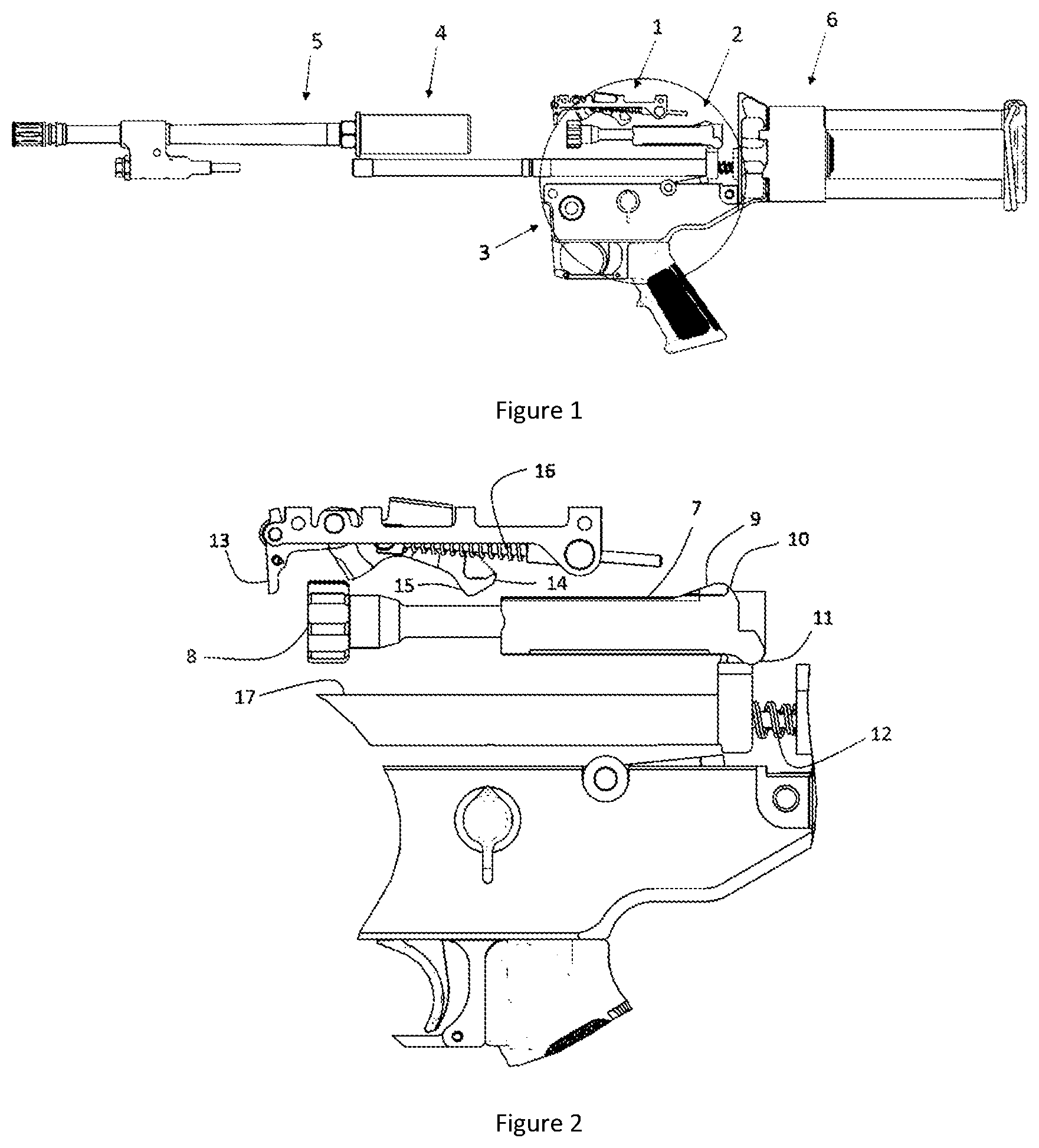
[0012] FIG. 1 depicts an overall view of a machinegun according to the invention, with the frame not depicted, so as to be able to see the various elements of the mechanism.
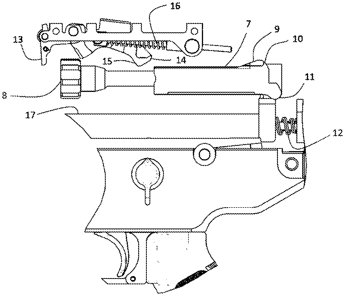
[0013] FIG. 2 depicts a view of a detail of the device of FIG. 1, showing the various components of the mechanism of the invention, upon release of the moving parts.
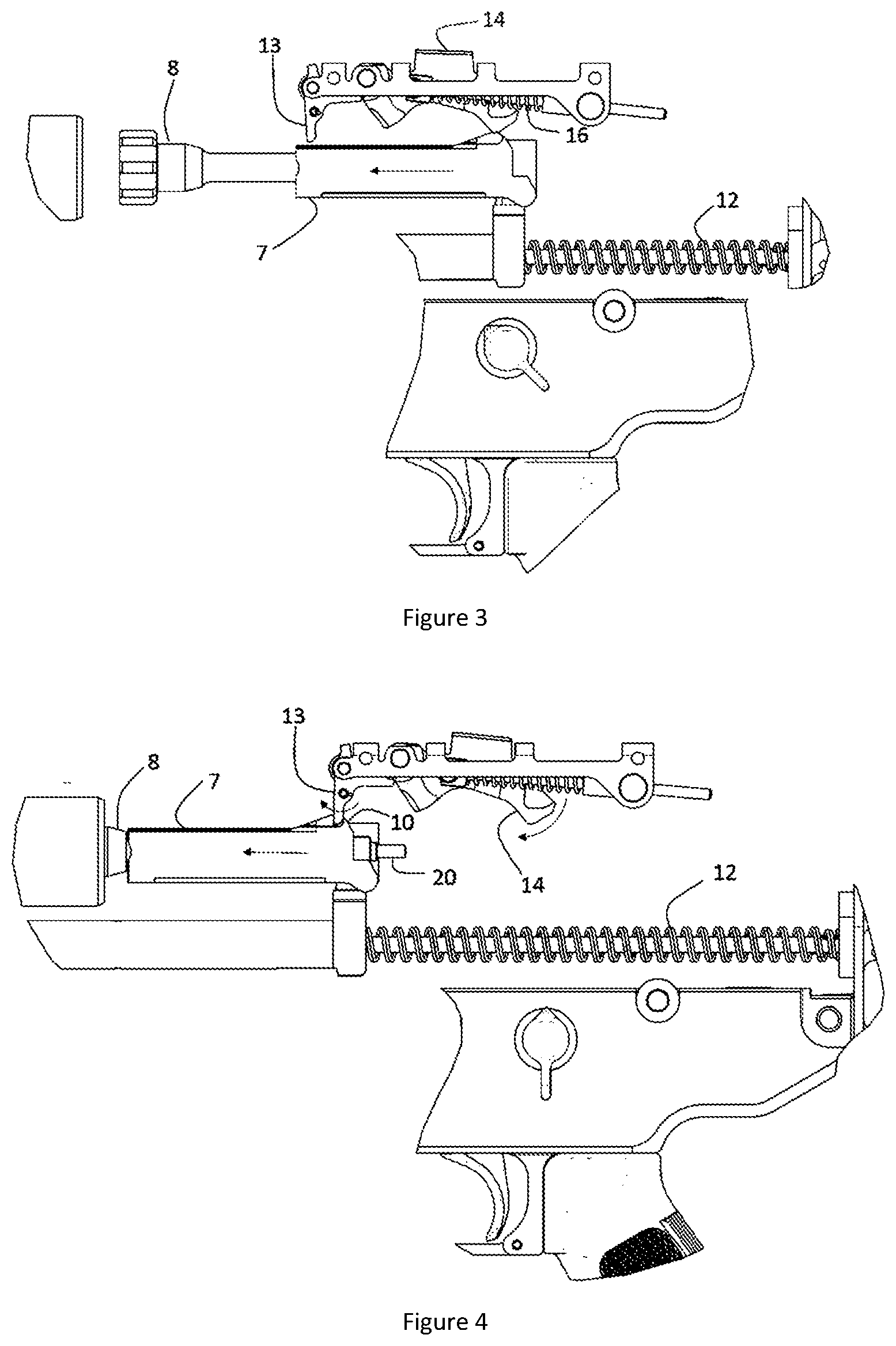
[0014] FIG. 3 depicts a detailed view of the mechanism of FIG. 1, during the forward movement of the moving parts.
[0015] FIG. 4 depicts a detailed view of the mechanism of FIG. 1, after the locking of the breech.
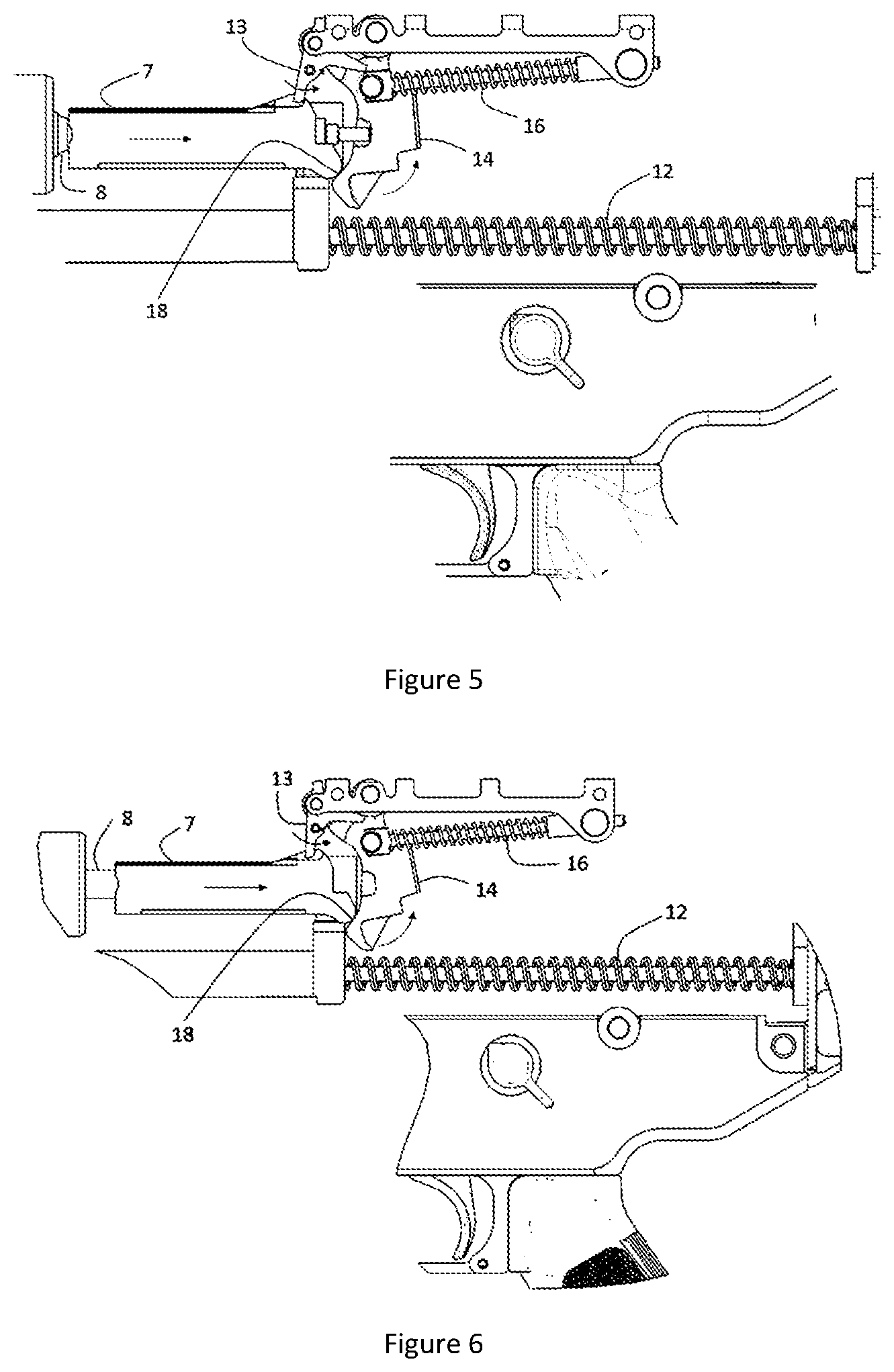
[0016] FIG. 5 depicts a detailed view of the mechanism of FIG. 1, just after the percussion.
[0017] FIG. 6 depicts a detailed view of the mechanism of FIG. 1, during the rearward return of the moving parts (intermediate position 1).
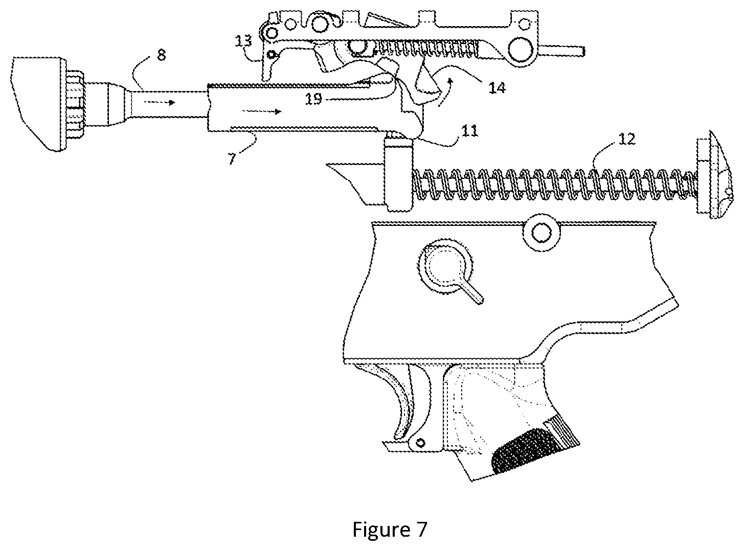
[0018] FIG. 7 depicts a detailed view of the mechanism of FIG. 1, during the rearward return of the moving parts (intermediate position 2).
REFERENCES IN THE FIGURES
[0019] 1. Hammer mechanism [0020] 2. Moving parts [0021] 3. Trigger mechanism (incorporated into the trigger guard) [0022] 4. Chamber [0023] 5. Barrel [0024] 6. Butt [0025] 7. Slide (sometimes also referred to as sliding block) [0026] 8. Bolt [0027] 9. Second hammer reloading cam [0028] 10. Hammer sear release cam [0029] 11. First hammer reloading cam [0030] 12. Recoil spring [0031] 13. Hammer sear [0032] 14. Hammer [0033] 15. Concave sliding surface [0034] 16. Hammer spring [0035] 17. Extension of the gas recovery piston [0036] 18. First point of reloading contact between slide and hammer [0037] 19. Second point of reloading contact between slide and hammer [0038] 20. Firing pin
DETAILED DESCRIPTION OF THE INVENTION
[0039] The present invention relates to a hammer mechanism 1 designed for firearms firing from an open bolt, in automatic or semiautomatic mode. In such a weapon, belt-fed loading from the top of the frame forces the designer to position the gas recovery and the recoil spring below the axis of the barrel 5 rather than above same.
[0040] The consequence of this positioning is that it is difficult to site a hammer mechanism incorporated into the trigger guard, as the latter is separated from the firing pin by the recoil spring and the bottom of the moving parts in the continuation of the gas recovery piston.
[0041] The present invention makes use of the fact that during open-bolt operation, initiation of firing (the start of the cycle) is associated not with the striking of a cartridge in the chamber 4 but with the release of the moving parts 2. That being the case, there is no longer any need to incorporate the hammer mechanism into the trigger guard, in mechanical connection with the trigger mechanism.
[0042] Rather, in the present invention, the release of the hammer 14 is controlled entirely by the movement of the slide 7, which ensures optimal synchronization between the locking of the breech by the bolt 8 and the percussion.
[0043] Because the hammer mechanism 1 is no longer connected with the trigger mechanism 3, it is then possible to position the hammer mechanism 1 above the axis of the barrel rather than below this axis.
[0044] FIG. 1 shows one example of a machinegun according to the invention, without the frame, in order to show the elements thereof. It shows a hammer mechanism 1 positioned above the axis of the barrel 5 and operating entirely autonomously. In particular, no mechanism connects the hammer mechanism 1 with the trigger mechanism 3.
[0045] FIGS. 2 to 7 show detailed views of the various elements of the percussion mechanism during a cycle of the machinegun. In FIG. 1, the moving parts are at rest awaiting firing. In that position, the hammer mechanism 1 is practically out of the path of the slide 7 and allows same to move freely forward, as depicted in FIG. 3.
[0046] FIG. 4 shows the end of the forward movement of the slide 7, at the moment of locking. At that moment, the cam 10 pushes the sear 13 forward, and this releases the hammer 14, which begins to rotate about its axis under the effect of the hammer spring 16.
[0047] FIG. 5 depicts the first few moments after percussion, at the start of the recoil of the moving parts 2. At this moment, as the slide 7 is recoiling, the cam 11 pushes on the sliding surface 15 beginning to compress the hammer spring. Note that the point 18 of contact between the slide 7 and the hammer 14 is as far away as possible from the axis of rotation of the hammer, so as to reduce the impact experienced by the hammer 14, and therefore the wearing and fatigue thereof, thus reducing the risk of breakage in the long term. The presence of the rounded cam 11 allows wear and fatigue to be reduced still further.
[0048] FIG. 6 depicts the continuation of the cycle, with the moving parts in a first intermediate position. Here it may be seen that the firing pin is effaced from the slide 7. In this recoil phase, the bolt 4 still remains attached to the chamber 4 while the slide 7 is already recoiling rearward.
[0049] FIG. 7 depicts the continuation of the cycle, the moving parts 2 being in a second intermediate position. In this position, the slide 7 pushes on the sliding surface via a second cam 9 this time arranged in the upper part of the slide. This is because, in this position, the distance between the axis of the hammer and the cam 9 is great enough for the acceleration of the hammer to be limited.
[0050] The hammer lifting dynamics are optimized by the adoption of a sliding surface 15 of the hammer in contact with the slide 7, which is concave. This is because this shape, combined with the presence of a cam 11 in the lower part of the rear of the slide 7, allows contact to be made first of all on a surface of the slide opposite the position of the hammer, thereby increasing the lifting lever arm and reducing the impact associated therewith. The curvature of this surface, with no sharp angles, also makes this movement more continuous and avoids impacts that could lead to material fatigue.
[0051] The end of the hammer lifting movement is brought about by a cam 9 situated on the upper surface of the slide 7. This cam 9 is set back with respect to the lower cam 11, so that the cam 11 acts at the start of the lift and the cam 9 at the end of the lift.
[0052] Note that the positioning of the hammer mechanism in the upper part of the weapon not only makes it possible to get around the problem of the bulkiness of the recoil spring and of the moving parts in the case of top loading, but also makes it possible to reduce the bulkiness of the trigger guard, allowing for a more compact design of the trigger guard.
* * * * *
D00000
D00001
D00002
D00003
D00004
XML
uspto.report is an independent third-party trademark research tool that is not affiliated, endorsed, or sponsored by the United States Patent and Trademark Office (USPTO) or any other governmental organization. The information provided by uspto.report is based on publicly available data at the time of writing and is intended for informational purposes only.
While we strive to provide accurate and up-to-date information, we do not guarantee the accuracy, completeness, reliability, or suitability of the information displayed on this site. The use of this site is at your own risk. Any reliance you place on such information is therefore strictly at your own risk.
All official trademark data, including owner information, should be verified by visiting the official USPTO website at www.uspto.gov. This site is not intended to replace professional legal advice and should not be used as a substitute for consulting with a legal professional who is knowledgeable about trademark law.