Heat Dissipation Device
Liu; Han-Min ; et al.
U.S. patent application number 16/531128 was filed with the patent office on 2021-02-11 for heat dissipation device. The applicant listed for this patent is ASIA VITAL COMPONENTS (CHINA) CO., LTD.. Invention is credited to Han-Min Liu, Xing-Xing Lyu, Jian Zhang.
| Application Number | 20210041181 16/531128 |
| Document ID | / |
| Family ID | 1000004381699 |
| Filed Date | 2021-02-11 |


| United States Patent Application | 20210041181 |
| Kind Code | A1 |
| Liu; Han-Min ; et al. | February 11, 2021 |
HEAT DISSIPATION DEVICE
Abstract
A heat dissipation device includes a base seat having a first chamber. The first chamber has multiple partitioning sections to partition the first chamber into multiple rooms without communicating with each other. A first working fluid is disposed in the rooms. Multiple two-phase fluid radiating fins are disposed on upper side of the base seat. Each of the two-phase fluid radiating fins is formed with an internal second chamber in communication with the rooms or not in communication with the rooms. The heat dissipation device can achieve better heat dissipation effect.
| Inventors: | Liu; Han-Min; (Shenzhen, CN) ; Zhang; Jian; (Shenzhen, CN) ; Lyu; Xing-Xing; (Shenzhen, CN) | ||||||||||
| Applicant: |
|
||||||||||
|---|---|---|---|---|---|---|---|---|---|---|---|
| Family ID: | 1000004381699 | ||||||||||
| Appl. No.: | 16/531128 | ||||||||||
| Filed: | August 5, 2019 |
| Current U.S. Class: | 1/1 |
| Current CPC Class: | F28D 15/04 20130101 |
| International Class: | F28D 15/04 20060101 F28D015/04 |
Claims
1. A heat dissipation device comprising a base seat having a first chamber, the first chamber having multiple partitioning sections to partition the first chamber into multiple rooms without communicating with each other, a first working fluid being disposed in the rooms, multiple two-phase fluid radiating fins being disposed on upper side of the base seat, each of the two-phase fluid radiating fins being formed with an internal second chamber in communication with the rooms or not in communication with the rooms.
2. The heat dissipation device as claimed in claim 1, wherein the base seat has an upper plate, a lower plate and a recess, the upper plate and the lower plate being correspondingly mated with each other, the recess being formed on the upper plate or the lower plate, the upper and lower plates and the recess together defining the first chamber, the partitioning sections being formed on the upper plate or the lower plate.
3. The heat dissipation device as claimed in claim 1, wherein the base seat and the two-phase fluid radiating fins are integrally formed.
4. The heat dissipation device as claimed in claim 1, wherein a first capillary structure is disposed in the first chamber, the first capillary structure being selected from a group consisting of mesh body, fiber body, porous structure body, channeled body and any combination thereof.
5. The heat dissipation device as claimed in claim 4, wherein a second capillary structure is disposed in each of the second chambers, the second capillary structure being selected from a group consisting of mesh body, fiber body, porous structure body, channeled body and any combination thereof.
6. The heat dissipation device as claimed in claim 5, further comprising a coating, the coating being correspondingly disposed on inner walls of the first and second chambers or disposed on the first and second capillary structures or disposed on both the inner walls of the first and second chambers and the first and second capillary structures.
7. The heat dissipation device as claimed in claim 1, wherein the first working fluid is a vapor-phase fluid or a vapor-liquid two-phase fluid.
8. The heat dissipation device as claimed in claim 1, wherein the rooms are not in communication with the second chambers and a second working fluid is disposed in the second chambers.
9. The heat dissipation device as claimed in claim 8, wherein the second working fluid is a vapor-phase fluid or a vapor-liquid two-phase fluid.
10. The heat dissipation device as claimed in claim 1, wherein the two-phase fluid radiating fins are formed by means of mechanical processing selected from a group consisting of aluminum extrusion, punching, die casting, drawing, injection and roll bonding.
11. The heat dissipation device as claimed in claim 1, wherein the base seat and the two-phase fluid radiating fins are made of a material selected from a group consisting of gold, silver, copper, copper alloy, aluminum, aluminum alloy, commercial pure titanium, titanium alloy and stainless steel.
12. A heat dissipation device comprising a base seat having a first chamber, the first chamber being one single independent chamber, a first working fluid being disposed in the first chamber, multiple two-phase fluid radiating fins being disposed on upper side of the base seat, each of the two-phase fluid radiating fins being formed with an internal second chamber not in communication with the independent chamber, a second working fluid being disposed in each of the second chambers.
13. The heat dissipation device as claimed in claim 12, wherein the base seat has an upper plate, a lower plate and a recess, the upper plate and the lower plate being correspondingly mated with each other, the recess being formed on the upper plate or the lower plate, the upper and lower plates and the recess together defining the first chamber.
14. The heat dissipation device as claimed in claim 12, wherein the base seat and the two-phase fluid radiating fins are integrally formed.
15. The heat dissipation device as claimed in claim 12, wherein a first capillary structure is disposed in the first chamber, the first capillary structure being selected from a group consisting of mesh body, fiber body, porous structure body, channeled body and any combination thereof.
16. The heat dissipation device as claimed in claim 15, wherein a second capillary structure is disposed in each of the second chambers, the second capillary structure being selected from a group consisting of mesh body, fiber body, porous structure body, channeled body and any combination thereof.
17. The heat dissipation device as claimed in claim 16, further comprising a coating, the coating being correspondingly disposed on inner walls of the first and second chambers or disposed on the first and second capillary structures or disposed on both the inner walls of the first and second chambers and the first and second capillary structures.
18. The heat dissipation device as claimed in claim 12, wherein the first working fluid is a vapor-phase fluid or a vapor-liquid two-phase fluid.
19. The heat dissipation device as claimed in claim 12, wherein the two-phase fluid radiating fins are formed by means of mechanical processing selected from a group consisting of aluminum extrusion, punching, die casting, drawing, injection and roll bonding.
20. The heat dissipation device as claimed in claim 12, wherein the base seat and the two-phase fluid radiating fins are made of a material selected from a group consisting of gold, silver, copper, copper alloy, aluminum, aluminum alloy, commercial pure titanium, titanium alloy and stainless steel.
Description
BACKGROUND OF THE INVENTION
1. Field of the Invention
[0001] The present invention relates generally to a heat dissipation device, and more particularly to a heat dissipation device including a base seat having a first chamber. Multiple two-phase fluid radiating fins are disposed on upper side of the base seat. Each of the two-phase fluid radiating fins is formed with an internal second chamber. A first working fluid is disposed in the first chamber and a second working fluid is disposed in the second chamber to achieve better heat dissipation effect.
2. Description of the Related Art
[0002] Along with the advance of sciences and technologies, the operation function and efficiency of various current electronic devices such as mobile devices, personal computers, servers, communication chasses, base stations and other systems or devices have become more and more powerful. The internal heat generation components (such as, but not limited to, chips and various power components) of these devices will all generate high heat in operation. Therefore, it is necessary to dissipate the heat of the heat generation components so as to avoid overheating of these heat generation components, which will lead to failure of these heat generation components. In general, a heat dissipation device is mounted on the heat generation components to prolong the lifetime thereof.
[0003] In the conventional heat dissipation device, solid radiating fins are disposed on the vapor chamber. The solid radiating fins serve to enlarge the heat dissipation area so as to enhance the heat dissipation effect. Alternatively, a fan can be further disposed to create greater air volume for dissipating the heat. However, the current mobile devices, personal computers, servers, communication chasses, base stations and other systems or devices have a narrow internal space so that it is hard to dispose a fan therein. Moreover, the heat conductivity of the material of the solid radiating fins itself will affect the heat dissipation effect. Therefore, the conventional heat dissipation device with the solid radiating fins disposed on the vapor chamber can hardly meet the industrial technical requirement in the future.
[0004] It is therefore tried by the applicant to provide a heat dissipation device, which can achieve better heat dissipation effect.
SUMMARY OF THE INVENTION
[0005] It is therefore a primary object of the present invention to provide a heat dissipation device, which can be used in a narrow space and an environment with low air volume. The heat dissipation device can achieve better heat dissipation effect without being affected by the heat conductivity of the material itself.
[0006] To achieve the above and other objects, the heat dissipation device of the present invention includes a base seat having a first chamber. The first chamber has multiple partitioning sections to partition the first chamber into multiple rooms without communicating with each other. A first working fluid is disposed in the rooms. Multiple two-phase fluid radiating fins are disposed on upper side of the base seat. Each of the two-phase fluid radiating fins is formed with an internal second chamber in communication with the rooms or not in communication with the rooms.
[0007] Still to achieve the above and other objects, the heat dissipation device of the present invention includes a base seat having a first chamber. The first chamber is one single independent chamber. A first working fluid is disposed in the first chamber. Multiple two-phase fluid radiating fins are disposed on upper side of the base seat. Each of the two-phase fluid radiating fins is formed with an internal second chamber not in communication with the independent chamber. A second working fluid is disposed in each of the second chambers.
[0008] In comparison with the conventional heat dissipation device with the solid radiating fins, the heat dissipation device of the present invention can be used in a narrow space and an environment with low air volume without being affected by the heat conductivity of the material itself so that the heat dissipation device of the present invention can achieve better heat dissipation effect.
BRIEF DESCRIPTION OF THE DRAWINGS
[0009] The structure and the technical means adopted by the present invention to achieve the above and other objects can be best understood by referring to the following detailed description of the preferred embodiments and the accompanying drawings, wherein:
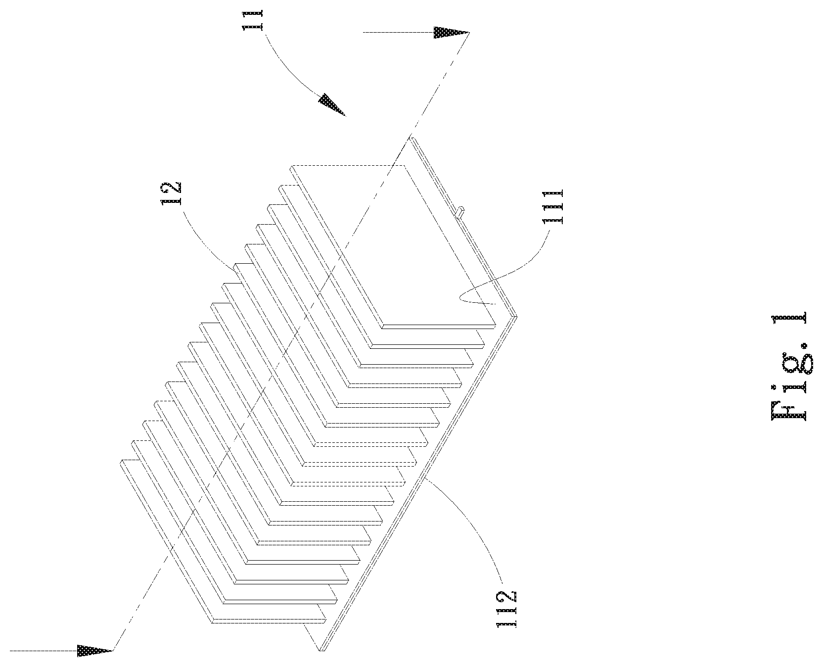
[0010] FIG. 1 is a perspective assembled view of a first embodiment of the heat dissipation device of the present invention;
[0011] FIG. 2 is a sectional assembled view of the first embodiment of the heat dissipation device of the present invention;
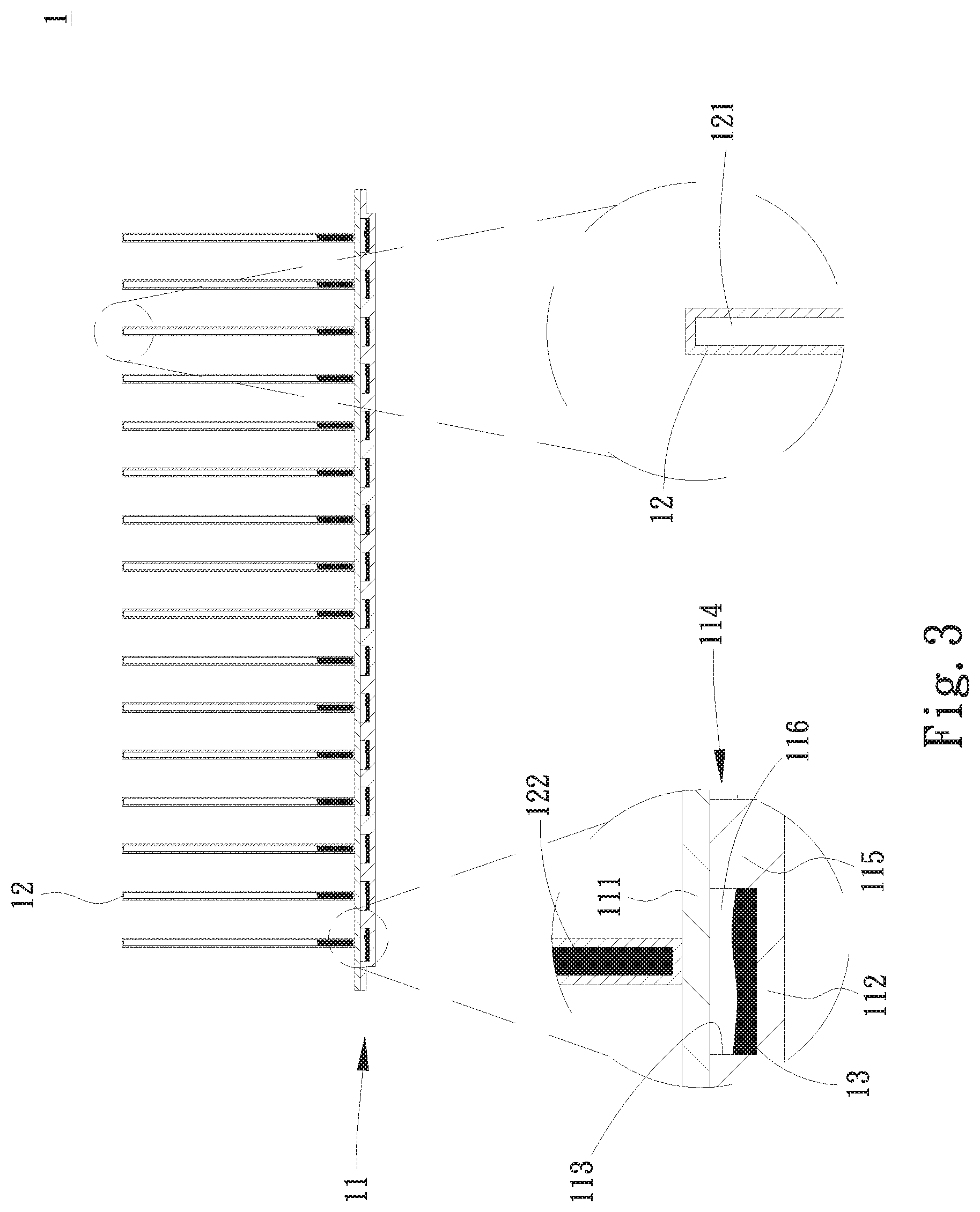
[0012] FIG. 3 is a sectional assembled view of a second embodiment of the heat dissipation device of the present invention;
[0013] FIG. 4 is a sectional assembled view of a third embodiment of the heat dissipation device of the present invention;
[0014] FIG. 5 is a sectional assembled view of a fourth embodiment of the heat dissipation device of the present invention;
[0015] FIG. 6 is a sectional assembled view of a fourth embodiment of the heat dissipation device of the present invention; and
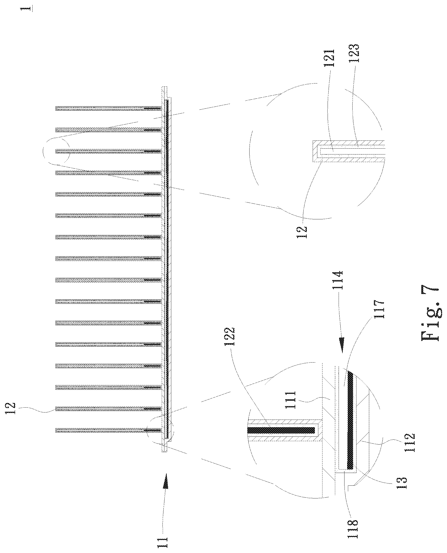
[0016] FIG. 7 is a sectional assembled view of a fourth embodiment of the heat dissipation device of the present invention.
DETAILED DESCRIPTION OF THE PREFERRED EMBODIMENTS
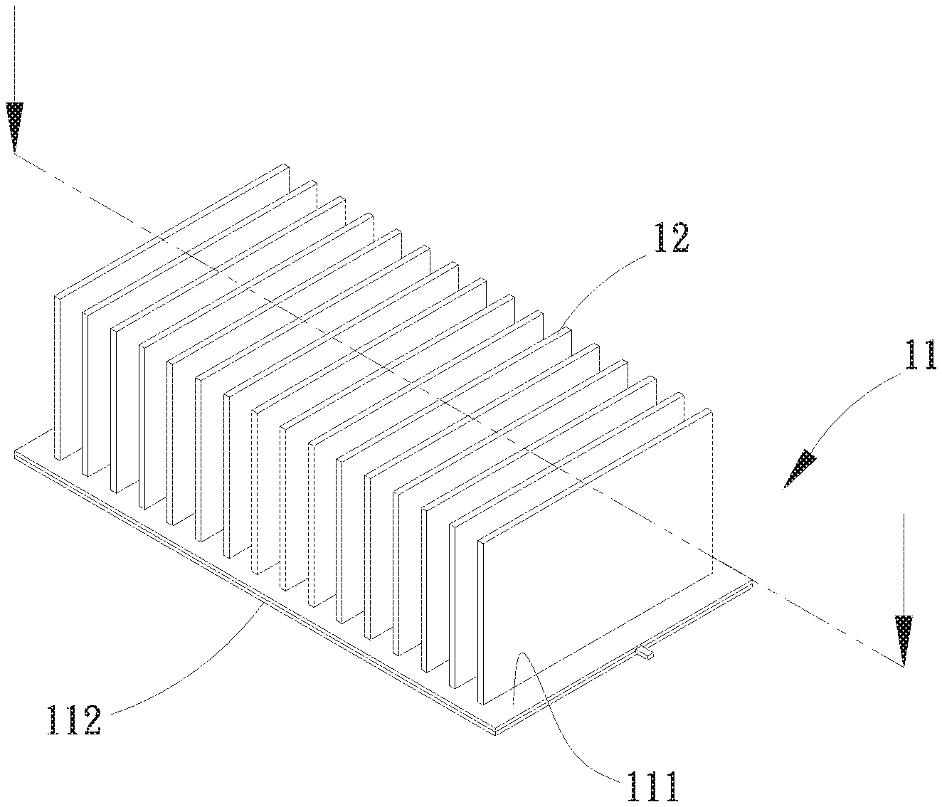
[0017] Please refer to FIGS. 1 and 2. FIG. 1 is a perspective assembled view of a first embodiment of the heat dissipation device of the present invention.
[0018] FIG. 2 is a sectional assembled view of the first embodiment of the heat dissipation device of the present invention. According to the first embodiment, the heat dissipation device 1 of the present invention is applied to a heat source of an electronic device for dissipating the heat of the heat source. In this embodiment, the heat dissipation device 1 is in contact and attachment with one or more heat generation components (not shown) disposed on a circuit board (such as a motherboard) of an electronic device so as to dissipate the heat of the heat generation components. The heat generation components can be, but not limited to, central processing unit and graphics processing unit. In practice, the heat generation components can be alternatively such as a Northbridge chip, a Southbridge chip, a transistor, a power component or any other electronic component on the circuit board that needs heat dissipation.
[0019] The heat dissipation device 1 includes a base seat 11, multiple two-phase fluid radiating fins 12 and a first working fluid 13. The base seat 11 has an upper plate 111, a lower plate 112, a recess 113 and a first chamber 114.
[0020] The upper plate 11 and the lower plate 112 are correspondingly mated with each other. The two-phase fluid radiating fins 12 are disposed on the upper plate 111 of the base seat 11. The lower side of the lower plate 112 is attached to the heat generation components to absorb heat. In this embodiment, the recess 113 is formed on the lower plate 112. In a modified embodiment, the recess 113 can be alternatively formed on the upper plate 111. The upper and lower plates 111, 112 and the recess 113 together define the first chamber 114. The first chamber 114 has multiple partitioning sections 115 to partition the first chamber 114 into multiple rooms 116. In this embodiment, the partitioning sections 115 are formed on the lower plate 112. In a modified embodiment, the partitioning sections 115 can be alternatively formed on the upper plate 111. The rooms 116 are not in communication with each other. The first working fluid 13 is disposed in the rooms 116. The first working fluid 13 is a vapor-phase fluid or a vapor-liquid two-phase fluid.
[0021] Each of the two-phase fluid radiating fins 12 is formed with an internal second chamber 121 in communication with the room 116. The two-phase fluid radiating fins 12 are formed by means of mechanical processing selected from a group consisting of aluminum extrusion, punching, die casting, drawing, injection and roll bonding. The base seat 11 and the two-phase fluid radiating fins 12 are made of a material selected from a group consisting of gold, silver, copper, copper alloy, aluminum, aluminum alloy, commercial pure titanium, titanium alloy and stainless steel. In this embodiment, the two-phase fluid radiating fins 12 are connected with the upper plate 111 in a manner selected from, but not limited to, a group consisting of welding, insertion, engagement, adhesion and latching. In a modified embodiment, the base seat 11 and the two-phase fluid radiating fins 12 are integrally formed by means of 3D printing.
[0022] According to the design of the present invention, the lower side of the base seat 11 absorbs the heat. Thereafter, the first working fluid 13 absorbs the heat of the base seat 11 in the rooms 116. The first working fluid 13 quickly transfers the heat in horizontal direction to spread the heat. At the same time, the first working fluid 13 enters the second chambers 121 to quickly transfer the heat in vertical direction. The two-phase fluid radiating fins 12 absorb the heat of the first working fluid 13 to radiate and dissipate the heat to the ambient environment. Therefore, in a narrow space and a low air volume environment, the heat dissipation device 1 of the present invention will not be affected by the heat conductivity of the material itself and is able to achieve better heat dissipation effect.
[0023] Please now refer to FIG. 3, which is a sectional assembled view of a second embodiment of the heat dissipation device of the present invention. Also referring to FIGS. 1 and 2, the second embodiment is partially identical to the first embodiment in structure and function and thus will not be redundantly described hereinafter. The second embodiment is different from the first embodiment in that the rooms 116 are not in communication with the second chambers 121. A second working fluid 122 is disposed in the second chambers 121. The second working fluid 122 is a vapor-phase fluid or a vapor-liquid two-phase fluid.
[0024] The lower side of the base seat 11 absorbs the heat. Thereafter, the first working fluid 13 absorbs the heat of the base seat 11 in the rooms 116. At the same time, the lower sides of the two-phase fluid radiating fins 12 absorb the heat of the base seat 11. The second working fluid 122 quickly transfers the heat in vertical direction. The two-phase fluid radiating fins 12 absorb the heat of the second working fluid 122 to radiate and dissipate the heat to the ambient environment. The rooms 116 are not in communication with the second chambers 121. Therefore, after the first working fluid 13 quickly transfers the heat in horizontal direction to spread the heat, the first working fluid 13 is condensed to flow from the upper plate 111 back to the lower plate 112 by a shorter distance. Therefore, the first working fluid 13 at lower temperature can be quickly provided for the heat generation components to absorb the heat.
[0025] Please now refer to FIG. 4, which is a sectional assembled view of a third embodiment of the heat dissipation device of the present invention. Also referring to FIG. 3, the third embodiment is partially identical to the second embodiment in structure and function and thus will not be redundantly described hereinafter. The third embodiment is different from the second embodiment in that the first chamber 114 is one single independent chamber 117 without any partitioning section 116. The independent chamber 117 in not in communication with the second chambers 121.
[0026] The first working fluid 13 in the independent chamber 117 can quickly transfer the heat in horizontal direction to the surrounding so as to spread the heat.
[0027] Please now refer to FIGS. 5 to 7. FIG. 5 is a sectional assembled view of a fourth embodiment of the heat dissipation device of the present invention. FIG. 6 is a sectional assembled view of a fourth embodiment of the heat dissipation device of the present invention. FIG. 7 is a sectional assembled view of a fourth embodiment of the heat dissipation device of the present invention. Also referring to FIGS. 1 to 4, the fourth embodiment is partially identical to the first, second and third embodiments in structure and function and thus will not be redundantly described hereinafter. The fourth embodiment is different from the first, second and third embodiments in that a first capillary structure 118 is disposed in the first chamber 114 and a second capillary structure 123 is disposed in each of the second chambers 121. The first and second capillary structures 118, 123 are selected from a group consisting of mesh body, fiber body, porous structure body, channeled body and any combination thereof.
[0028] In the case that the rooms 116 are in communication with the second chambers 121, the first and second capillary structures 118, 123 are capillarily connected with each other (as shown in FIG. 5). By means of the first and second capillary structures 118, 123, after condensed in the second chambers 121, the first working fluid 13 can quickly flow back to the rooms 116. In the case that the rooms 116 (as shown in FIG. 6) or the one single independent chamber 117 (as shown in FIG. 7) is not in communication with the second chambers 121, after condensed on the upper plate 111, the first capillary structure 118 can make the first working fluid 13 quickly flow back to the lower plate 112. Also, after condensed in the upper side of the second chamber 121, the second capillary structure 123 can make the second working fluid 122 quickly flow back to the lower side of the second chamber 121.
[0029] The term "capillarily connected" mentioned above means the porous structure of the first capillary structure 118 communicates with the porous structure of the second capillary structure 123, whereby the capillary attraction can be transferred or extended from the capillary structure 118 to the second capillary structure 123.
[0030] In a modified embodiment, the second capillary structure 123 is omitted and the first and second working fluids 13, 122 flow back under gravity.
[0031] In still a modified embodiment, a coating (not shown) is disposed on the inner walls of the first and second chambers 114, 121 or disposed on the first and second capillary structures 118, 123 or disposed on both the inner walls of the first and second chambers 114, 121 and the first and second capillary structures 118, 123 so as to enhance the hydrophilicity of the inner walls of the first and second chambers 114, 121 and the first and second capillary structures 118, 123. Accordingly, the first and second working fluids 13, 122 can more quickly and collectively flow back.
[0032] The present invention has been described with the above embodiments thereof and it is understood that many changes and modifications in such as the form or layout pattern or practicing step of the above embodiments can be carried out without departing from the scope and the spirit of the invention that is intended to be limited only by the appended claims.
* * * * *
D00000
D00001
D00002
D00003
D00004
D00005
D00006
D00007
XML
uspto.report is an independent third-party trademark research tool that is not affiliated, endorsed, or sponsored by the United States Patent and Trademark Office (USPTO) or any other governmental organization. The information provided by uspto.report is based on publicly available data at the time of writing and is intended for informational purposes only.
While we strive to provide accurate and up-to-date information, we do not guarantee the accuracy, completeness, reliability, or suitability of the information displayed on this site. The use of this site is at your own risk. Any reliance you place on such information is therefore strictly at your own risk.
All official trademark data, including owner information, should be verified by visiting the official USPTO website at www.uspto.gov. This site is not intended to replace professional legal advice and should not be used as a substitute for consulting with a legal professional who is knowledgeable about trademark law.