Heat Exchangers And Methods Of Making The Same
HENDERSON; STEVEN WILLIAM JAMES ; et al.
U.S. patent application number 16/534887 was filed with the patent office on 2021-02-11 for heat exchangers and methods of making the same. The applicant listed for this patent is MEGGITT AEROSPACE LIMITED. Invention is credited to JENNA NICOLE BECKER, STEVEN WILLIAM JAMES HENDERSON, RICCARDO MARIA LOMONACO.
| Application Number | 20210041178 16/534887 |
| Document ID | / |
| Family ID | 1000004485817 |
| Filed Date | 2021-02-11 |


| United States Patent Application | 20210041178 |
| Kind Code | A1 |
| HENDERSON; STEVEN WILLIAM JAMES ; et al. | February 11, 2021 |
HEAT EXCHANGERS AND METHODS OF MAKING THE SAME
Abstract
Heat exchanger designs incorporating helixes and methods for making heat exchangers incorporating helixes are provided herein. In preferred embodiments, the heat exchanger comprises a plurality of fluid A channels each formed from a tube spiraled into a helix to form a plurality of helixes wherein the plurality of helixes are arranged in a hexagonal packing arrangement in a packing plane perpendicular to the axes of rotation of the plurality of helixes and wherein the pitch of each helix in the plurality of helixes is matched to an exterior diameter of the tube such that each helix in the plurality of helixes has a sealed interior that forms a plurality of fluid B channels.
| Inventors: | HENDERSON; STEVEN WILLIAM JAMES; (RUGBY, GB) ; BECKER; JENNA NICOLE; (LEAMINGTON SPA, GB) ; LOMONACO; RICCARDO MARIA; (CHRISTCHURCH, GB) | ||||||||||
| Applicant: |
|
||||||||||
|---|---|---|---|---|---|---|---|---|---|---|---|
| Family ID: | 1000004485817 | ||||||||||
| Appl. No.: | 16/534887 | ||||||||||
| Filed: | August 7, 2019 |
| Current U.S. Class: | 1/1 |
| Current CPC Class: | F28D 7/0066 20130101 |
| International Class: | F28D 7/00 20060101 F28D007/00 |
Claims
1. A heat exchanger comprising: a plurality of fluid B channels in a heat exchanger matrix; a plurality of fluid A channels in the heat exchanger matrix where each fluid A channel in the plurality of fluid A channels is comprised of a hollow tube that spirals around the outside of a fluid B channel from the plurality of fluid B channels and forms a helix, and wherein each spiral in the helix is close enough together to adjacent spirals so that an exterior of the tube in each spiral is continuously touching an exterior of the tube in each adjacent spiral such that the exterior of the tube the forms the helix forms an interior of the fluid B channel.
2. The heat exchanger of claim 1, wherein the fluid B channels have a longitudinal axis that is straight.
3. The heat exchanger of claim 1, wherein the fluid B channels are all the same size diameter.
4. The heat exchanger of claim 1, wherein a plurality of helixes are arranged with their longitudinal axis in a plurality of parallel rows and wherein each row in the plurality of rows is offset from an adjacent row by an exterior diameter of one helix.
5. The heat exchanger of claim 4, wherein the offset of each row alternates back and forth such that the longitudinal axes in every other row align.
6. The heat exchanger of claim 5, wherein the rows are separated by less than an exterior diameter of one helix.
7. The heat exchanger of claim 1, wherein the tubes have a round exterior.
8. The heat exchanger of claim 1, further comprising a header that is coupled to the plurality of fluid A channels and has openings where the plurality of fluid B channels pass through the header.
9. The heat exchanger of claim 2, wherein the plurality of fluid B channels have a packing plane that is perpendicular to their longitudinal axis and the plurality of fluid B channels are arranged in a hexagonal packing arrangement.
10. A heat exchanger comprising: a plurality of helixes wherein a longitudinal axis of rotation of each helix in the plurality of helixes is parallel and wherein each helix in the plurality of helixes is formed by a hollow tube that spirals around the longitudinal axis of rotation and wherein each tube forms a fluid A channel and wherein the pitch of each helix in the plurality of helixes is matched to an exterior diameter of the tube that comprises the helix such that each helix in the plurality of helixes has a sealed interior and each sealed interior forms a fluid B channel.
11. The heat exchanger of claim 10, wherein the longitudinal axis of rotation of each helix is straight.
12. The heat exchanger of claim 10, wherein the fluid B channels all have a same size exterior diameter.
13. The heat exchanger of claim 10, wherein the plurality of helixes are arranged with their longitudinal axis of rotation in a plurality of parallel rows and wherein each row in the plurality of rows is offset from an adjacent row by an exterior diameter of one helix.
14. The heat exchanger of claim 13, wherein the offset of each row alternates back and forth such that all the longitudinal axes of rotation in every other row align.
15. The heat exchanger of claim 14, wherein the rows are separated by less than an exterior diameter of one helix.
16. The heat exchanger of claim 10, wherein the tubes have a round exterior.
17. The heat exchanger of claim 10, further comprising a header that is coupled to the plurality of fluid A channels and has openings where the plurality of fluid B channels pass through the header.
18. A heat exchanger comprising: a plurality of fluid A channels each formed from a hollow tube spiralled into a helix to form a plurality of helixes wherein the plurality of helixes are arranged in a hexagonal packing arrangement in a packing plane perpendicular to axes of rotation of the plurality of helixes and wherein the pitch of each helix in the plurality of helixes is matched to an exterior diameter of the tube such that each helix in the plurality of helixes has a sealed interior that forms a plurality of fluid B channels.
19. The heat exchanger of claim 18, wherein the fluid B channels are all the same size diameter.
20. The heat exchanger of claim 18, wherein the fluid B channels have different size diameters.
21. The heat exchanger of claim 18, wherein a bend radius of the hollow tube of the helix is varied along a length of the helix.
22. The heat exchanger of claim 18, wherein a plurality of fluid A channels are intertwined to create a single fluid B channel.
Description
FIELD
[0001] This patent document relates to heat exchangers and methods of making the same. In particular, this patent document relates to new geometric designs for heat exchangers that result in heat exchangers with improved efficiencies.
BACKGROUND
[0002] Heat exchangers are used in multiple applications within a vast range of industries. Because of the importance of heat exchangers, there is a constant push to develop heat exchangers that are more efficient, lighter, more compact, more durable and more cost effective. Generally, the industry is always looking for improved heat exchanger designs that optimize one or more parameters of the heat exchanger, depending on the application.
[0003] The demands on heat exchangers are becoming particularly more challenging in the area of aircraft engines. Engines have evolved dramatically in the last fifty years. Traditionally, engine nacelles housed a multitude of components including the heat exchangers. With increasing fan diameters, the drag generated by the nacelle becomes too large, necessitating thinner, slim-line nacelles. These thinner nacelles cannot house the components traditionally housed within the nacelle. Instead, these components have to be housed within the core zone. As the core zone already houses ducting, pipework, bleed systems and other components, relocating hardware previously housed within the nacelle can prove to be a challenge due to envelope constraints.
[0004] As the fan diameter increases, it has become necessary to reduce the fan speed, relative to the turbine speed, via a reduction gearbox. Heat load from the accessories' gearbox, bearings and generators is typically used to pre-heat the fuel with excess heat being fed into the secondary flow air or air flow external to the nacelle. It is estimated that the additional gearbox will double the heat load introduced into the oil. This additional heat load can only be dissipated into the secondary flow air as the fuel cannot accept any further temperature increases.
[0005] As engine manufacturers strive towards more fuel-efficient architectures, systems which are usually driven by compressor discharge pressure, such as ECS, are being powered by electric systems. These systems put extra demand on the electrical generators, again this additional energy results in extra heat load being dissipated into the oil.
[0006] As the space around the core of the engine begins to fill with equipment, emphasis is put on reducing the space taken up by individual pieces of equipment. This begins a significant challenge for the heat exchangers where they are required to manage approximately double the heat load but in a smaller volume.
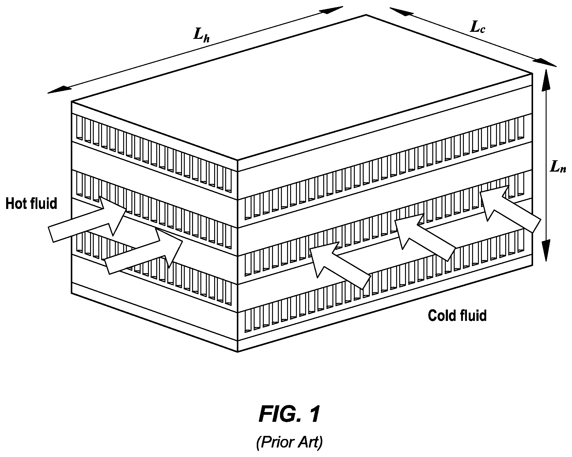
[0007] Applicant currently designs and manufactures plate and fin construction heat exchangers for air oil and low-pressure fuel oil applications. An illustration of a plate and fin heat exchanger can be seen in FIG. 1.
[0008] Plate and fin heat exchangers are constructed from layers of corrugated fins sandwiched between parting plates. The fins are supported by bars which are located at either end of the fin layer. The heat exchangers transfer heat from the hot fluid of the heat exchanger (depending on the application of the heat exchanger) to the metal surrounding the fluids. The fins act as secondary heat transfer surface area and transfer the heat to the other fluid via conduction. Side plates cap the top and bottom of the plate/fin stack.
[0009] The fins and the parting plates are typically 3000 series aluminum. The corrugated surfaces (fins) are produced on a fin forming machine in a variety of patterns e.g. plain, lanced, wavy, perforated or louvered. In most cases the height of the fin and fin density can be tailored to the operating conditions and mechanical constraints of the particular application. Parting plates, or separator sheets as they are also known, are usually from thin gauge material and are clad with a braze alloy on both sides to allow bonding to the fin surfaces. Side plates may be cut from sheet. This would be clad on one side only or, if thicker plates are required for strength, a brazing shim may be added to allow bonding. The bars that close each layer of the core are made from a specific extruded section or may be machined from solid if a particular feature in the core is a requirement.
[0010] The heat exchanger core is then assembled in purpose designed fixtures and brazing jigs. The upper platform of the jig is under spring pressure pushing the surfaces together as the core contracts as the clad surfaces disperse to form the joints and fuse together during the brazing process.
[0011] The resulting heat exchanger is restricted to rectangular shapes by their construction. The construction also constrains the heat exchanger to being formed in discrete layers. This results in the necessity to use fins to add additional surface area. The fins are classed as secondary heat transfer surface area which has an inherent inefficiency associated with the convective and conductive heat transfer. The layered construction also limits the variation in the flow configurations that can be employed; where typically for plate and fin heat exchangers cross-flow configurations are used. Parallel flow or counter flow can be used but require complex and expensive header constructions.
[0012] In recent years, advancements in additive manufacturing have made it a viable option for the production of heat exchangers and heat exchanger components. The use of additive manufacturing for heat exchangers has opened up new possibilities for heat exchanger geometries. In particular, heat exchangers can now be made with geometries that do not have to conform to standard manufacturing principals.
[0013] Applicant has previously recognized the advantages of using additive manufacturing in the manufacture of heat exchangers. U.S. patent application Ser. No. 16/242,432 (hereinafter "'432 application") was filed on Jan. 8, 2019, and covers a series of designs for heat exchangers manufactured using additive manufacturing. Although the heat exchanger designs in the '432 application are created using additive manufacturing, they are very different from heat exchanger designs disclosed herein.
[0014] For at least the reasons above, there is a need for new heat exchanger designs that improve on previous designs in any of the heat exchangers criteria but in particular in the areas of efficiency, size and weight.
SUMMARY OF THE EMBODIMENTS
[0015] Objects of the present patent document are to provide an improved heat exchanger and improved methods for making heat exchangers. To this end, various embodiments of heat exchangers and methods of making heat exchangers are provided. In preferred embodiments, the heat exchanger comprises: a plurality of fluid B channels in a heat exchanger matrix; a plurality of fluid A channels in the heat exchanger matrix where each fluid A channel in the plurality of fluid A channels is comprised of a tube that spirals around the outside of a fluid B channel from the plurality of fluid B channels and forms a helix, and wherein each spiral in the helix is close enough together to adjacent spirals such that an exterior of the tube in each spiral is continuously touching an exterior of the tube in each adjacent spiral such that the exterior of the tube forms an interior of the fluid B channel.
[0016] In preferred embodiments, the heat exchanger has fluid B channels with a longitudinal axis that is straight. In addition, the fluid B channels are preferably all the same size diameter. Of course, in other embodiments, the fluid B channels can have different sized diameters. This may be beneficial for the packing density of the fluid B channels.
[0017] In preferred embodiments, the heat exchanger comprises a plurality of helixes that are arranged with their longitudinal axis in a plurality of parallel rows, wherein each row in the plurality of rows is offset from an adjacent row by an exterior diameter of one helix.
[0018] In some embodiments, the offset of each row of helixes in the heat exchanger matrix alternates back and forth such that all the longitudinal axis of the helixes in every other row align. In some embodiments, the rows are separated by less than an exterior diameter of one helix.
[0019] Generally speaking, the tubes that comprise the fluid A channels, and whose touching exteriors form the fluid B channels have a round exterior. However, the tube exterior may be any shape including square, hexagon or triangular, to name a few.
[0020] In preferred embodiments, the heat exchanger further comprises a header that is coupled to the plurality of fluid A channels and has openings where the plurality of fluid B channels pass through the header.
[0021] In preferred embodiments, the fluid B channels are packed as tightly as possible to maximize efficiency of the heat exchanger. Accordingly, the plurality of fluid B channels may have a packing plane that is perpendicular to their longitudinal axis and the plurality of fluid B channels are arranged in a hexagonal packing arrangement.
[0022] In yet other embodiments of heat exchangers taught herein, the heat exchangers comprise a plurality of helixes wherein a longitudinal axis of rotation of each helix in the plurality of helixes is parallel and wherein each helix in the plurality of helixes is formed by a tube that spirals around the longitudinal axis of rotation and wherein each tube is hollow and forms a fluid A channel and wherein the pitch of each helix in the plurality of helixes is matched to an exterior diameter of the tube such that each helix in the plurality of helixes has a sealed interior and each sealed interior forms a fluid B channel for the heat exchanger.
[0023] In some embodiments, the heat exchangers are designed to have the plurality of helixes arranged with their longitudinal axis of rotation in a plurality of parallel rows and each row in the plurality of rows is offset from an adjacent row by an exterior diameter of one helix.
[0024] In yet other embodiments heat exchangers are provided that comprise a plurality of fluid A channels each formed from a tube spiraled into a helix and collectively forming a plurality of helixes wherein each helix has an axis of rotation that is parallel to each other helix in the plurality of helixes and wherein the plurality of helixes are arranged in a hexagonal packing arrangement in a packing plane perpendicular to the axis of rotation of the plurality of helixes and wherein the pitch of each helix in the plurality of helixes is less than or equal to an exterior diameter of the tube such that each helix in the plurality of helixes has a sealed interior that forms a plurality of fluid B channels.
[0025] As may be appreciated, the embodiments described herein are especially efficient because the larger fluid B channels have no additional structure of their own and are comprised entirely from the tubes of the helix shaped fluid A channels.
[0026] The heat exchangers discussed herein may use a header to feed the smaller fluid A channels. Accordingly, the heat exchangers may further comprise a header that is coupled to the plurality of fluid A channels but has openings where the gas or liquid feeding the plurality of fluid B channels washes over the outer wall of the header prior to entering the fluid B channels. To this end, embodiments herein may have thermally active headers.
[0027] The headers that feed and drain the fluid A channels are separated by the heat exchanger matrix and may be found on opposite sides of the heat exchanger matrix. These headers may be thought of as secondary headers and may each be fed by a primary header. To this end, in some embodiments, the heat exchanger further comprises an input primary header coupled to a secondary header on a first side of the heat exchanger matrix and an output primary header coupled to a secondary header on a second side opposite to the first side of the heat exchanger matrix.
BRIEF DESCRIPTION OF THE DRAWINGS
[0028] FIG. 1 illustrates an exterior isometric view of a plate and fin heat exchanger according to the prior art.
[0029] FIG. 2 illustrates a cut-away schematic view of the plate and fin heat exchanger of FIG. 1.
[0030] FIG. 3 illustrates an exterior isometric view of a heat exchanger according to the teachings herein.
[0031] FIG. 4 illustrates a cross-sectional view of the heat exchanger matrix of the heat exchanger in FIG. 3.
[0032] FIG. 5A is an isometric view of the heat exchanger of FIGS. 3A and 3B with a plurality of the flow paths of the hot fluid, or first fluid ("A Channels"), schematically illustrated.
[0033] FIG. 5B is an isometric view of the heat exchanger of FIGS. 4A, 3A and 3B with the flow path of the cold fluid, or second fluid ("B Channel"), schematically illustrated.
[0034] FIG. 6A illustrates a cross-sectional view of a helix where the pitch of the helix is equal or about equal to the diameter of the tube.
[0035] FIG. 6B illustrates a cross-sectional view of a helix where the pitch of the helix is less than the diameter of the tube.
[0036] FIG. 7 illustrates an embodiment where helical fluid A channels are intertwined in parallel within a single column.
[0037] FIG. 8 illustrates an example of a helix where the bend radius of the helical tubes is varied along the coil's length.
DETAILED DESCRIPTION OF THE DRAWINGS
[0038] The present patent document describes embodiments of heat exchangers that eliminate or at least ameliorate some of the problems with previous heat exchanger designs. FIG. 3 illustrates an exterior isometric view of a heat exchanger 10 according to the teachings herein. The heat exchanger in FIG. 3 is comprised of three main components: the heat exchanger matrix 12, also known as the heat exchanger core 12, secondary headers 14 and feeder (primary) headers 16. As may be seen in FIG. 3, the heat exchanger matrix 12 is comprised of a plurality of helixes 11 that extend up and down along an axis of rotation, in this embodiment, the Z-axis. In other words, the helixes 11 have axes of rotations that are all parallel to the Z-axis. It may also be appreciated that the helixes 11 are arranged or packed along both the X and Y axis. Accordingly, the helixes 11 have a packing plane perpendicular to the Z-axis.
[0039] Each helix 11 in the matrix core 12 is comprised by a tube that spirals around an axis of rotation to create a helix. The tubes are hollow and allow the flow of air or fluid through their interiors.
[0040] FIG. 4 illustrates a cross-sectional view of the heat exchanger matrix of the heat exchanger in FIG. 3. The spiraling tubes create the individual helixes 11 and the interior of each tube is a fluid A channel 22 of the heat exchanger 10. Accordingly, the heat exchangers of the present patent document are comprised of a plurality of fluid A channels 22 each consisting of a tube that spirals around an axis of rotation 15 to form a helix 11.
[0041] The interior of each helix 11 forms a fluid B channel 24. In order to maintain unmixed flow, the interior of each helix 11 is designed to be continuous such that fluid cannot leak between the interiors of different helixes 11, fluid B channels 24. To this end, in preferred embodiments, each spiral in the helix 11 is close enough together to adjacent spirals above and below such that an exterior of the tube in each spiral is continuously touching an exterior of the tube in each adjacent spiral. Said another way, the pitch of each helix 11 is matched to the exterior diameter of the tube that comprises the helix 11 such that each helix 11 has a sealed interior and each sealed interior forms a fluid B channel 24. By "matched" it is meant that the pitch is small enough with respect to the tube diameter to seal the interior once manufactured. To this end, embodiments herein require the pitch of each helix 11 to be less than or equal to the outside diameter of the tube creating the helix 11. Consequently, the exterior of the tube that spirals around and is the fluid A channel 22 forms an interior of the fluid B channel 24.
[0042] To this end, each fluid A channel 22 in the plurality of fluid A channels 22 spirals around the outside of a fluid B channel 24. The fluid B channels 24 are formed from the interior of each helix 11. As may be appreciated, the axis of rotation 15 of each helix 11 forms the longitudinal axis or central axis of each fluid B channel 24. As a fluid or gas spirals around the helix 11 inside the tube that comprises the helix 11, the fluid or gas traverses in a negative Z-axis direction. A second fluid or gas may then be passed in the opposite direction, the positive Z-axis direction, up through the interior of the helixes 11, which define the fluid B channels 24.
[0043] Accordingly, the exterior walls of the smaller fluid A channels 22 all come in contact to form the larger fluid B channels 24. Each fluid B channel 24 in the plurality of fluid B channels 24 is formed by a spiraling a fluid A channel 22 around an axis of rotation 15 to form a helix 11.
[0044] The fluid A channels 22 are helical tubes grouped tightly to form the matrix 12, and the fluid B channels 24 are formed from the interior of each helix 11. By using helical tubes, the fluid A channels 22 have an increased heat transfer length and heat transfer surface area per volume. Helical channels also offer increased heat transfer performance over a straight channel of the same length, due to centrifugal forces inducing a secondary flow in the form of Dean vortices.
[0045] Because the fluid B channels 24 are formed from the interior of the fluid A channels 22, the fluid B channels 24 are ribbed which leads to increased heat transfer area. The novel channel packaging, with the fluid A channels 22 tightly packed around the fluid B channels 24, means that the heat transfer surface area of the fluid B channels 24 is entirely primary surface area; this results in increased heat transfer performance as there is no compound restriction on secondary surface area efficiency. Although the figures in this document present the fluid A and fluid B channels as circular, these channels can be any shape that fulfils the performance and packaging requirements.
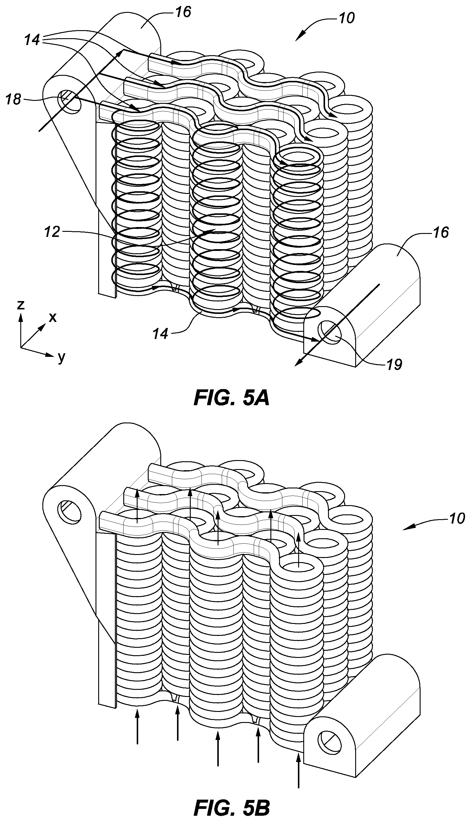
[0046] FIG. 5A is an isometric view of the heat exchanger of FIGS. 3 and 4 with a plurality of the flow paths of the hot fluid, or fluid A channels, schematically illustrated. As may be seen in FIG. 5A, in operation, hot fluid enters the feeder header, or primary header, 16 through the input port 18. As the hot fluid begins to fill the feeder header 16, the hot fluid moves in the positive X direction along the length of the feeder header 16. The feeder header 16 is in communication with the secondary headers 14 that stretch in the positive Y direction across the tops of the inputs to the fluid A channels 22. The primary headers 16 hold the full mass flow rate of the fluid A channels 22 and feed the plurality of secondary headers 14. The secondary headers 14 in turn feed each layer of the fluid A channels 11.
[0047] In the embodiments shown herein, the secondary headers 14 are S-shaped and follow the contours of the tops of the plurality of fluid A channels 22 as the secondary headers 14 stretch across the heat exchanger matrix 12. This allows the secondary headers 14 to feed the fluid A channels 22, while not blocking the fluid B channels 24. Accordingly, the fluid B channels 24 pass completely through the secondary headers 14 on both sides of the heat exchanger. In operation, the outer surfaces of the secondary headers 14 are washed by the fluid B flow entering and exiting the fluid B channels 24 of the heat exchanger 10 and therefore allow for the transfer of heat from fluid A within the headers 11 to fluid B.
[0048] As the hot fluid fills the secondary headers 14 that stretch across the top of the heat exchanger 10, the hot fluid begins to pass down the fluid A channels 22 in the negative Z direction towards the bottom of the heat exchanger 10. Accordingly, the hot fluid spirals around each helix 11 as it traverses in the negative Z direction. Eventually the hot fluid reaches the bottom of the fluid A channels 22 and then passes back into a secondary header 14 at the bottom of the heat exchanger 10.
[0049] The secondary headers 14 at the bottom of the heat exchanger 10 are similar to the secondary headers on the top of the heat exchanger 10 but just on the bottom instead of on the top. Just like on the top, the secondary headers 14 on the bottom run primarily in the Y direction across the bottom of the fluid A channels 22 and are fed by the fluid A channels 22 and the feeder header 16 on the bottom of the heat exchange 10. The hot fluid then flows through the secondary headers 14 on the bottom of the heat exchanger 10 in the positive Y direction towards the bottom feeder header (output header) 16. Eventually the hot fluid enters the bottom feeder header 16 and exits through the exit port 19.
[0050] Although the entrance and exit 18 and 19 of the primary headers 16 of the embodiment shown in FIG. 5A illustrate the fluid entering and exiting from the same side, in other embodiments, the primary headers 16 can be adapted to allow fluid to enter and exit on opposite sides or from above or below or any other direction. Likewise, the inlet and outlet headers 16 are pictured as being on opposite sides, but could also be positioned on the same side.
[0051] FIG. 5B is an isometric view of the heat exchanger of FIG. 5A with the flow path of the cold fluid, or second fluid ("fluid B channels") 24, schematically illustrated. While the "hot fluid" is flowing through the fluid A channels 22, the cold gas or cold fluid enters the fluid B channels on the bottom of the heat exchanger 10 and flows up in the positive Z direction towards the top of the heat exchanger 10 and out the top of the fluid B channels 24 and heat exchanger 10. As the cold air flows up in the positive Z direction through the fluid B channels 24 and the hot fluid flows down in the negative Z direction through the fluid A channels, the heat is transferred from the hot fluid into the cold air. To this end, the temperature of the hot fluid is reduced as it passes through the heat exchanger 10.
[0052] In the example of operation above, the terms hot fluid and cold gas were used but in either case the substances could be in gas or fluid phase. In addition, while typically the hot fluid would be passed through the fluid A channels 22, and the cold gas or fluid through the fluid B channels 24, in some embodiments the cold fluid could be used in the fluid A channels 22 and the hot gas in the fluid B channels 24. Moreover, the heat exchanger 10 could be run in reverse with the hot fluid flowing up and the cold fluid flowing down. In the embodiments herein, the heat exchanger 10 is designed and manufactured so that it can be used in a counter flow or parallel flow configuration. While counter flow is the optimal configuration for maximum heat transfer performance, there may be scenarios where parallel flow configuration is preferred. Accordingly, the embodiments herein can be run in a parallel flow configuration or a counterflow configuration.
[0053] As may be appreciated, the designs suggested herein would be incredibly difficult, if not completely impossible, to manufacture using any type of conventional manufacturing method. To this end, the designs herein are preferably manufactured using additive manufacturing. The additive manufacturing techniques allow for the compact packaging of the heat exchanger flow channels and enable the novel designs and the flexibility in design embodied herein. Moreover, the additive manufacturing process allows the heat exchanger to be built as a single piece.
[0054] Many different types of materials may be used with the additive manufacturing process. To this end, the designs herein may be made from aluminum (and associated alloys), steel (and associated alloys), titanium (and associated alloys), Inconel (and associated alloys) or any other type of metal that may be used in the additive manufacturing process. Some prototype heat exchangers were manufactured in aluminum using additive manufacturing and these prototypes are expected to achieve a circa five-fold increase in the yield strength compared to conventional 3000 series aluminum used in the plate and fin construction. Depending on the application, it may also be possible to use a hardened resin or even a ceramic. Basically, any material that may be used in the additive manufacturing process may be used and that includes materials that may be not yet available for the process but available in the future. Of course, materials with good heat transfer properties are desirable.
[0055] In various different embodiments, the general concepts of the heat exchangers taught herein may be modified to optimise the performance for a particular application. To this end, the embodiments herein may be optimized for their performance and pressure drop through the heat exchanger for bespoke applications. For example, the cross-section of the fluid A channels 22 is shown as round or tubular. However, other shapes may be used for the cross-section of the fluid A channels 22 including squares, triangles, hexagons or ellipses, to name a few. Moreover, the interior of the tubes or fluid A channels 22 could be one shape and the exterior could be a different shape. As just one example, the exterior of the tubes may be round while the interior is a more complex shape. The interior of the fluid A channels 22 may also include flow features on their surface. The shape of the cross-section of the fluid A channels 22 may be changed to any shape in order to fulfil the performance, structural, and packaging requirements of any particular application.
[0056] In addition, the layout and packing of the fluid B channels may be changed. As may be seen in FIG. 4, in the embodiments shown herein, a plurality of helixes 11 are arranged with their longitudinal axis 15, a.k.a. axis of rotation 15, in a plurality of parallel rows that run along the X axis. In the embodiment shown in FIG. 4, each row of helixes 11 in the plurality of rows is offset from an adjacent row by an exterior diameter of one helix. The offset of each row alternates back and forth such that the longitudinal axes 15 in every other row align in the Y-axis direction. In the embodiment shown in FIG. 4, the rows are separated by less than an exterior diameter of one helix to pack the helixes closely.
[0057] While a particular packing of helixes 11 or packing of the fluid B channels 24 is described and shown with respect to FIG. 4, various other packing or packaging methods may be used. As may be appreciated, a cross-section of the heat exchanger matrix 12 may be considered a packing plane. The study of packing geometric shapes into various different configurations within a packing plane is well studied. The cross-section of a helix is typically a circle and the study of packing circles in a plane is extensive. Circles may be packed in triangular, diamond, or hexagonal packing arrangements with the hexagonal packing arrangement being the densest arrangement and therefore, most desirable. Moreover, it is also known that packing densities of circles may be increased by allowing the diameter of the circles to vary and accordingly, heat exchangers may be constructed with varying diameter helixes 11 to allow for a denser packing. As discussed in more detail below, the diameter of the helixes 11 may also be varied for performance reasons and both design criteria may be considered in finding the optimal helix size, spacing and packing for any particular application.
[0058] In preferred embodiments, the packing is designed for maximum density and thus, the helixes are packed with their external surfaces touching. Packing arrangements for the helixes 11, such as hexagonal packing, may be further selected to maximize density.
[0059] In other embodiments, the helixes may be constructed such that their cross-sections are oval or some other shape rather than circles. In yet other embodiments, the cross-sections of different helixes within the heat exchanger matrix may vary in shape. In all these embodiments, different packing arrangements within the packing plane may be used to optimize performance for any particular application.
[0060] In the embodiments illustrated in the figures herein, the heat exchanger matrix is shown generally as a square block where the fluid B channels 24 have a straight axis of rotation 15 and the number of helixes 11 are grouped to allow the heat exchanger to have approximately the same dimension along the X and Y axes. However, for applications where the flow path is not a straight line, the geometries of the fluid B channels may be changed and may include fluid B channels 24 with an axis of rotation that is a "swept path" (e.g. curved, wavy, zigzag, helix etc.) to conform to the desired flow path. In more complex embodiments, the diameter of the tube of each helix 11 may vary along different parts of the helix 11 to allow the interior of the fluid B channels 24 to stay continuous and sealed as the axis of rotation 15 of the helix 11 curves. Changing the diameter of the tube along the length of the helix can allow the thickness of the walls of the tube to stay consistent even as the axis of rotation of the helix curves. In general, it is preferable that the thickness of the tubes that comprise the helixes 11/fluid A channels 22 remains constant. However, in yet other embodiments, the thickness of the walls of the tube that forms the helixes 11 may also vary to accommodate various design constraints.
[0061] In some embodiments, the secondary headers 14 on the top and/or bottom of the heat exchanger 10 may be profiled or shaped to promote turning of the fluid B flow in inclined or other applications. This allows the secondary headers 14 to perform their function both as headers and also as air foils to direct the B flow. This type of dual-purpose header is only possible in designs where the A channel headers are actively in the path of the channel B flow. The integrated thermally active headers 14 can be profiled or shaped to reduce entrance pressure losses into the fluid B flow channels 24 for flows which are both normal to and angled relative to the channel flow stream. The angle range covers 0 degrees to 90 degrees and can be a compound angle relative to more than one axis.
[0062] In yet other embodiments, the channel packing and channel geometry or cross section may be variable and may be made to match the fluid B flow profile. In order to enhance the ducted systems performance, variable channel geometries can be used within the heat exchanger to take advantage of non-uniform velocity profiles at the heat exchanger inlet. For example, the size of or density of the fluid A and/or B channels 22 and/or 24 may be varied across the profile of the heat exchanger 10 to match the flow distribution. Changing channel density or size to match the flow distribution can help with pressure drop and efficiency. To this end, the size of the fluid A and/or B channels 22 and/or 24 may increase from one side of the heat exchanger 10 to another. In yet other embodiments, the size of the fluid B channels 24 may be larger in any particular row or column of the cross section. In yet other embodiments, multiple strategically placed rows or columns of the cross-section have larger fluid B channels 24 to accommodate the flow profile. As discussed above, the diameter of the fluid B channels 24 may also be varied to increase packing density and both design criteria can drive the size and placement of the fluid A and/or B channels 22 and/or 24.
[0063] Further improvements to the heat exchanger performance can also be made with a variable cold flow length to further maximise performance with non-uniform velocity profiles, the manifestation of this concept would include curved inlet and/or outlet faces.
[0064] In some embodiments, the primary headers 16 may fully encompass the heat exchanger perimeter, which could act as flanges for integration with ducting. In a conventional plate & fin heat exchanger, flanges are typically added around the perimeter of the airflow entrance and exit planes. These flanges are used as attachment points to the inlet and outlet air ducts. In the designs proposed herein, the primary headers 16, which are each along one edge of the airflow entrance/exit perimeters, can be extended to encompass the entire perimeter, and the primary headers 16 can mount directly to the inlet/outlet ducting. This would make the primary headers 16 dual-purpose and eliminate the need for mounting flanges.
[0065] When manufacturing the embodiments herein, additive manufacturing may be used to create the entire structure as one piece. Manufacturing the entire heat exchanger as one piece reduces the secondary machining process or joining methods, reduces part count and simplifies the supply chain. In yet other embodiments, the primary headers 16 may be made separately and coupled to the heat exchanger matrix 12 and secondary headers 14 after they have been manufactured. In yet other embodiments, the heat exchanger matrix 12 is made with additive manufacturing and both the primary headers 16 and secondary headers 14 are manufactured separately and coupled to the heat exchanger matrix 12 after the three components are manufactured.
[0066] The heat exchanger has been designed and manufactured with fluid A channel wall thicknesses ranging from 0.2 mm to 0.5 mm. The wall thickness can be used as a design variable, where the wall thicknesses can be tailored to suit the operating pressures while minimizing the weight and maximising the compactness of the heat exchanger. Wall thicknesses between 0.1 mm and 10 mm may be used depending on the application and structural and thermal requirements. The thinner the wall thickness the better the thermal performance at the expense of the structural performance. The thicker the walls the better the structural performance at the expense of the thermal performance.
[0067] In some embodiments, additional secondary heat transfer `micro features` can be added to the surfaces of the fluid A 22 and/or B channels 24. As just a few non-limiting examples of micro-features, dimples, protrusions, vortex generators etc., may be added to the surfaces of the fluid A channels 22 and/or fluid B channels 24. Such micro features are used to further increase heat transfer surface area and convective heat transfer.
[0068] In the embodiments taught and disclosed herein, the fluid B channels 24 are created entirely from the negative space not used by the construction of the fluid A channels. Consequently, no additional material is required to create the fluid B channels. This leads to weight reduction (no extra materials required to separate the fluids) and increased primary surface (approaching 100%).
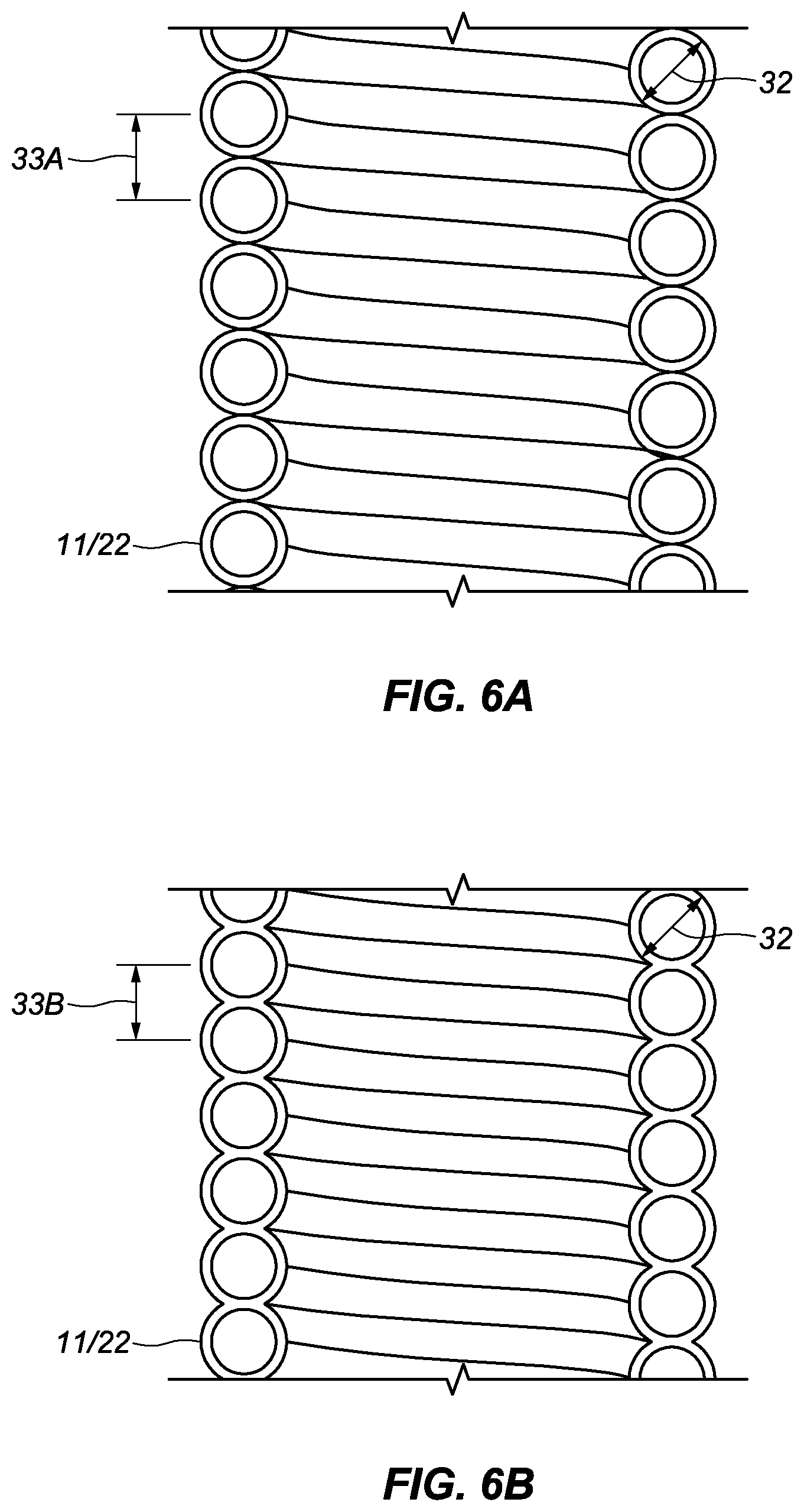
[0069] In preferred embodiments, the pitch of the helixes of the fluid A channels 22 is designed to be matched with the diameter of the tubes creating the fluid A channels 22 such that the interior of the helixes are sealed. However, in some embodiments, the pitch of the helixes may be less than the diameter of the tubes such that the walls of the coils in the helix overlap. FIG. 6A illustrates a cross-sectional view of a helix where the pitch of the helix is equal or approximately equal to the diameter of the tube. FIG. 6B illustrates a cross-sectional view of a helix where the pitch of the helix is less than the diameter of the tube. Accordingly, it can be seen that the upper and lower walls of the fluid A channels 22 in each turn of the helix overlap with the walls of each adjacent spiral. The amount of overlap can be any amount but preferably the amount of overlap never exceeds the thickness of one tube. Otherwise, the adjacent tubes would protrude into the interiors of each adjacent tube, which is not ideal.
[0070] Where neighboring spirals within a given helix 11 share walls, i.e. the pitch 33A/33B of the helix is less than the exterior diameter of the tube 32, a weight reduction and volume reduction may occur while maintaining the same surface area. As may be appreciated by comparing FIG. 6A to FIG. 6B, a helix 11 with the same number of spirals and the same interior and exterior diameter tube 32, may be compressed into a smaller height by overlapping the walls of the spirals within the helix 11. Accordingly, in comparing FIG. 6A to 6B, it will be appreciated that while the exterior diameter 32 of the tube is identical in the two examples, the pitch 33A of the helix 11 in FIG. 6A is slightly larger than the pitch 33B of the helix 11 in FIG. 6B.
[0071] In preferred embodiments, the overlap of the walls of the tube is 50% of the wall thickness. In yet other embodiments, the overlap is greater and is between 50% and 90% of the wall thickness. In yet other embodiments, the overlap of the walls is less than 50% of the wall thickness. In yet other embodiments the walls overlap almost completely and the overlap is between 90% and 100% of the wall thickness. As may be appreciated, the pitch of the helix is equal to the diameter of the tube minus 2 times the overlap distance.
[0072] In addition to a pitch reduction that results in an overlap of the walls of the tube within each helix, the helixes may be spaced in the packing plane such that their walls overlap. This may be done independently or in combination with overlapping the walls within a helix. Neighboring coils can share walls by simply reducing the distance between their axes of rotation, for example, in the packing plane. Sharing walls between neighboring helixes can not only reduce the size of the heat exchanger but can also reduce weight and add structural stiffness. To this end, it is recommended that helixes actually do overlap. Similar to the overlap within the helixes themselves, the amount of overlap between neighboring helixes can vary but should not exceed the thickness of the tube wall.
[0073] In preferred embodiments, the overlap of the walls of neighboring helixes is 50% of the wall thickness. In yet other embodiments, the overlap is greater and is between 50% and 90% of the wall thickness. In yet other embodiments, the overlap of the walls is less than 50% of the wall thickness. In yet other embodiments the walls overlap almost completely and the overlap is between 90% and 100% of the wall thickness.
[0074] FIG. 7 illustrates an embodiment where helical channels 41, 42 and 43 are intertwined parallel within a single column. To this end, more than one fluid A channel 22 is combined to create a single fluid B channel 24. As shown in FIG. 7, three fluid A channel 22 helixes are combined to create a single fluid B channel 24; however, in other embodiments, 2, 4, 5 or more fluid A channels can be combined to create a single B channel 24. In the embodiment of FIG. 7, all three helixes are designed to have the identical pitch which is equal to or less than the sum of the diameters of the three tubes. As explained above, if the tube walls are designed to overlap, the pitch may be less than the sum of the three diameters by an amount proportional to the wall overlap. In different embodiments, helical channels can be intertwined in a single column, either in parallel or in series. Any number of helical fluid A channels 22 can be combined to create a single fluid B channel 24.
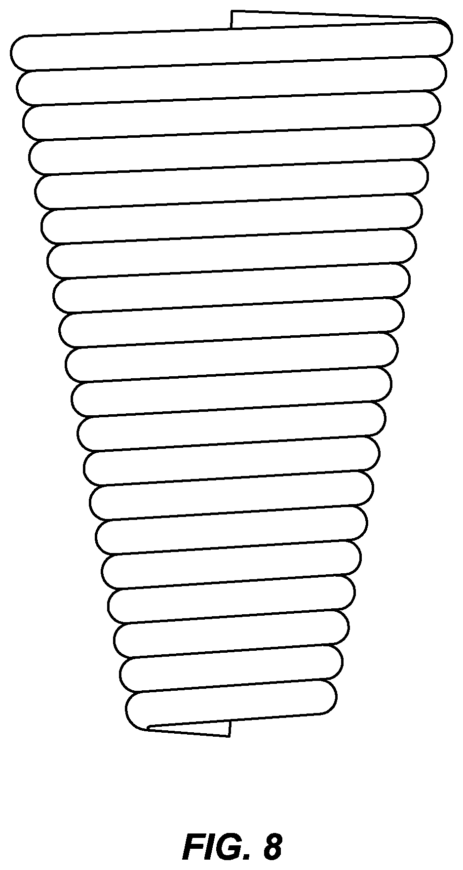
[0075] FIG. 8 illustrates an example of a helix where the bend radius of the helical tubes is varied along the coil's length. This results in a conical shaped coil. In embodiments of heat exchangers, helixes with varied bend radius along their lengths can be used. In some embodiments, every other helix has a bend radius that varies in the opposite direction along its length such that the resulting cones fit tight together with a helix with a large base surrounded by helixes with small bases and vice versa.
[0076] As may be appreciated from the specification herein, there are a number of design choices that may be changed to allow the design of a heat exchanger to fit a particular set of requirements without departing from the scope of what is taught herein. This leads to the ability to modify the overall heat exchanger form to be curved, conical, and/or include conformal regions to enable design flexibility when integrating the heat exchanger design into the engine environment or some other environment.
[0077] There is no limit whatsoever on the type of application the heat exchangers described herein may be used for. The applications for the heat exchanger include but are not limited to Air-Oil cooling such as: main oil circuit, oil cooling; power gearbox (fan reduction) oil circuit; integrated drive generator (IDG) oil circuit, oil cooling; variable frequency generator (VFG) oil circuit, oil cooling; permanent magnet generator (PMG) oil circuit, oil cooling. The applications for the heat exchanger may also be used for Air to Air cooling such as: Turbine blade/guide vane cooling; and buffer seal air cooling.
[0078] While there is no limit on the type of applications the heat exchangers described herein may be used for, the Applicant designed the heat exchangers herein to be used in aerospace applications and believes they are particularly suited for those types of applications. As one example, the heat exchanger can be integrated within a Ducted Air Oil Mini System. The ducting within the mini system connects the heat exchanger to the bypass duct air flow. In this configuration the air flow is directed through the heat exchanger prior to being returned to the bypass duct. The air entering the heat exchanger is used as a heat sink for the hotter fluid being passed through the fluid channels within the heat exchanger. In order for the ducting and heat exchanger to be integrated, the primary header can be designed and manufactured so that the header fully encompasses the core of the heat exchanger and becomes the mounting interface between the ducting and the heat exchanger.
[0079] Some of the advantages of the heat exchanger designs discussed herein are: 1) A counter flow configuration with novel thermally active header arrangement; A header that aids the heat transfer performance by being in the fluid B pathway; 3) 100% primary heat transfer surface area improving heat transfer performance per unit volume; 4) Compact fluid A and fluid B packaging arrangement, which increases the flow area and heat transfer surface area per unit volume; 5) Helical construction is structurally robust and offers improved heat transfer over a straight tube; 6) Can be constructed in a one-piece build, reducing part count and the secondary machining process or joining methods; 7) Secondary surface area can be added to the fluid A and B channels to further enhance the heat transfer performance; 8) Shaped fluid A headers can be used, which could act as turning features in inclined heat exchanger applications; and 9) Variable fluid B channel dimensions that match the inlet flow profile can be used to further improve the efficiency of the system.
* * * * *
D00000
D00001
D00002
D00003
D00004
D00005
D00006
D00007
XML
uspto.report is an independent third-party trademark research tool that is not affiliated, endorsed, or sponsored by the United States Patent and Trademark Office (USPTO) or any other governmental organization. The information provided by uspto.report is based on publicly available data at the time of writing and is intended for informational purposes only.
While we strive to provide accurate and up-to-date information, we do not guarantee the accuracy, completeness, reliability, or suitability of the information displayed on this site. The use of this site is at your own risk. Any reliance you place on such information is therefore strictly at your own risk.
All official trademark data, including owner information, should be verified by visiting the official USPTO website at www.uspto.gov. This site is not intended to replace professional legal advice and should not be used as a substitute for consulting with a legal professional who is knowledgeable about trademark law.