Exhaust Gas Treatment Assembly Unit
DATZ; Wolfgang ; et al.
U.S. patent application number 16/986618 was filed with the patent office on 2021-02-11 for exhaust gas treatment assembly unit. The applicant listed for this patent is Eberspacher Exhaust Technology GmbH. Invention is credited to Wolfgang DATZ, Markus HENZLER, Peter KAST.
| Application Number | 20210040874 16/986618 |
| Document ID | / |
| Family ID | 1000005022607 |
| Filed Date | 2021-02-11 |


View All Diagrams
| United States Patent Application | 20210040874 |
| Kind Code | A1 |
| DATZ; Wolfgang ; et al. | February 11, 2021 |
EXHAUST GAS TREATMENT ASSEMBLY UNIT
Abstract
An exhaust gas treatment assembly unit for an exhaust system of an internal combustion engine includes a tubular outer housing (12) elongated in a direction of an outer housing longitudinal axis (L.sub.A), a tubular inner housing (14) elongated in the direction of an inner housing longitudinal axis (L.sub.I), an exhaust gas treatment unit (16) being carried in the inner housing (14), and a locking fixing device (24) detachably fixing the inner housing in the outer housing. The locking fixing device (24) includes a locking fixing element (26) held at the inner housing (14) in both axial directions with a radially outwards prestressed locking meshing area (28). In association with the locking meshing area (28), a locking receiving area (42) at the outer housing (12), interacts with the locking meshing area (28) for holding the inner housing (14) in the outer housing (12) in at least one axial direction.
| Inventors: | DATZ; Wolfgang; (Tubingen, DE) ; HENZLER; Markus; (Grafenberg, DE) ; KAST; Peter; (Esslingen, DE) | ||||||||||
| Applicant: |
|
||||||||||
|---|---|---|---|---|---|---|---|---|---|---|---|
| Family ID: | 1000005022607 | ||||||||||
| Appl. No.: | 16/986618 | ||||||||||
| Filed: | August 6, 2020 |
| Current U.S. Class: | 1/1 |
| Current CPC Class: | F01N 13/1805 20130101; F01N 2450/18 20130101; F01N 3/28 20130101; F01N 13/1844 20130101 |
| International Class: | F01N 3/28 20060101 F01N003/28; F01N 13/18 20060101 F01N013/18 |
Foreign Application Data
| Date | Code | Application Number |
|---|---|---|
| Aug 8, 2019 | DE | 10 2019 121 411.4 |
Claims
1. An exhaust gas treatment assembly unit for an exhaust system of an internal combustion engine, the exhaust gas treatment assembly unit comprising: a tubular outer housing elongated in a direction of an outer housing longitudinal axis; a tubular inner housing elongated in a direction of an inner housing longitudinal axis, wherein an exhaust gas treatment unit is carried in the inner housing; and a locking fixing device configured to detachably fix the inner housing in the outer housing, wherein the locking fixing device comprises: a locking fixing element, held at the inner housing in both axial directions, with a radially outwards prestressed locking meshing portion; and a locking receiving area associated with the locking meshing portion and interacting with the locking meshing portion for holding the inner housing in the outer housing in at least one axial direction, at the outer housing.
2. The exhaust gas treatment assembly unit in accordance with claim 1, wherein the locking receiving area comprises a radially inwardly open locking depression extending in at least some areas in a circumferential direction about the outer housing longitudinal axis.
3. The exhaust gas treatment assembly unit in accordance with claim 2, wherein: the locking receiving area comprises a groove locking depression extending without interruptions in a circumferential direction about the outer housing longitudinal axis; or the locking receiving area comprises a plurality of locking depressions following one another in the circumferential direction about the outer housing longitudinal axis and arranged at circumferentially spaced locations from one another.
4. The exhaust gas treatment assembly unit in accordance with claim 1, wherein the locking fixing element comprises further locking meshing portions to provide a plurality of locking meshing portions arranged at spaced locations from one another in a circumferential direction about the inner housing longitudinal axis.
5. The exhaust gas treatment assembly unit in accordance with claim 4, wherein the locking fixing element has a ring-shape configuration.
6. The exhaust gas treatment assembly unit in accordance with claim 5, wherein: the locking fixing element comprises a ring body extending in the circumferential direction about the inner housing longitudinal axis along an inner side of the inner housing with the plurality of locking meshing portions arranged at circumferentially spaced locations from another and projecting radially outwards with respect to the ring body; a plurality of locking receiving areas are provided comprising passage openings provided in the inner housing in association with each of locking meshing portions, which locking meshing portions each project radially outwards from the ring body, the locking meshing portions projecting over an outer side of the inner housing for meshing with an associated locking receiving area.
7. The exhaust gas treatment assembly unit in accordance with claim 5, wherein: the locking fixing element is configured as a wire ring; or the locking fixing element is interrupted in the circumferential direction and has circumferential ends arranged at circumferentially spaced locations from one another.
8. The exhaust gas treatment assembly unit in accordance with claim 1, wherein the locking fixing device comprises further locking fixing elements to provide a plurality of locking fixing elements that follow one another in a circumferential direction about the inner housing longitudinal axis.
9. The exhaust gas treatment assembly unit in accordance with claim 8, wherein: the locking fixing device comprises further holding areas, with each of the holding areas holding one of the locking fixing elements at the inner housing in both axial directions; each of the locking fixing elements comprises at least one of the locking meshing portions projecting radially outwards with respect to the holding area.
10. The exhaust gas treatment assembly unit in accordance with claim 9, wherein each of the holding areas comprise holding sections arranged at spaced locations from one another in the circumferential direction about the inner housing longitudinal axis.
11. The exhaust gas treatment assembly unit in accordance with claim 10, wherein at least one of the holding sections comprises a holding element provided integrally at the locking fixing element.
12. The exhaust gas treatment assembly unit in accordance with claim 10, wherein at least one of the holding sections comprises a holding element configured separately from the locking fixing element.
13. The exhaust gas treatment assembly unit in accordance with claim 11, wherein the holding sections comprise a holding element extending around or/and passing through the inner housing.
14. The exhaust gas treatment assembly unit in accordance with claim 9, wherein the locking fixing element is configured as a shaped wire part.
15. The exhaust gas treatment assembly unit in accordance with claim 11, wherein: the locking fixing element is configured as a shaped wire part; and at least one of the holding elements is provided by a U-shaped end section of the locking fixing element, which said U-shaped end section extends around the inner housing.
16. The exhaust gas treatment assembly unit in accordance with claim 9, wherein the locking fixing element is configured as a shaped sheet metal part.
17. The exhaust gas treatment assembly unit in accordance with claim 11, wherein at least one of the holding elements is provided by an end section of the locking fixing element, which said end section passes through an opening in the inner housing.
18. The exhaust gas treatment assembly unit in accordance with claim 12, wherein at least one of the holding elements is fixed by a connection in substance at the inner housing.
19. The exhaust gas treatment assembly unit in accordance with claim 10, wherein the locking fixing element is fixed by a connection in substance at the inner housing in at least one holding section.
20. The exhaust gas treatment assembly unit in accordance with claim 12, wherein at least one holding element is configured as a shaped sheet metal part.
21. The exhaust gas treatment assembly unit in accordance with claim 9, wherein the holding area comprises a holding section arranged at a circumferentially spaced location or/and at an axially spaced location from the locking meshing portion.
22. The exhaust gas treatment assembly unit in accordance with claim 21, wherein: the holding section is fixed by a connection in substance at the inner housing; or the holding section passes through the inner housing; or the holding section is fixed by a connection in substance at the inner housing and the holding section passes through the inner housing.
23. The exhaust gas treatment assembly unit in accordance with claim 21, wherein the locking fixing element is configured as a shaped wire part and that the holding section is configured integrally with the locking fixing element.
24. The exhaust gas treatment assembly unit in accordance with claim 9, wherein: the holding area comprises two holding sections arranged at spaced locations from one another in the direction of the inner housing longitudinal axis and extending radially inwards over the inner housing from the outer side and extending behind the inner housing on an inner side and a support section supported on the outer side of the inner housing between the holding sections; the locking meshing portion projects radially outwards for meshing with an associated locking receiving area and is provided between the support section and one of the holding sections.
25. The exhaust gas treatment assembly unit in accordance with claim 24, wherein each holding section comprises: at least one holding leg extending over the inner housing in an area of a passage opening or in the area of an axial end of the inner housing from radially outwards to radially inwards; and a holding projection projecting axially with respect to the holding leg and extending behind the inner housing on an inner side.
26. The exhaust gas treatment assembly unit in accordance with claim 24, wherein the locking fixing element is configured as a shaped sheet metal part.
27. The exhaust gas treatment assembly unit in accordance with claim 1, further comprising mounting material arranged between the inner housing and the outer housing.
28. The exhaust gas treatment assembly unit in accordance with claim 27, wherein: the locking fixing device acts in an axial end area of the inner housing between the inner housing and the outer housing; and the mounting material is provided at least in another axial end area of the inner housing between the inner housing and the outer housing.
29. The exhaust gas treatment device in accordance with claim 27, wherein: the mounting material is held under compression between the inner housing and the outer housing; or the mounting material comprises wire material; or the mounting material is held under compression between the inner housing and the outer housing and the mounting material comprises wire material.
Description
CROSS REFERENCE TO RELATED APPLICATIONS
[0001] This application claims the benefit of priority under 35 U.S.C. .sctn. 119 of German Application DE 10 2019 121 411.4, filed Aug. 8, 2019, the entire contents of which are incorporated herein by reference.
TECHNICAL FIELD
[0002] The present invention pertains to an exhaust gas treatment assembly unit for an exhaust system of an internal combustion engine, comprising a tubular outer housing elongated in the direction of an outer housing longitudinal axis and a tubular inner housing elongated in the direction of an inner housing longitudinal axis, wherein an exhaust gas treatment unit is carried in the inner housing. Such an exhaust gas treatment unit may be, for example, a catalytic converter or a particle filter.
SUMMARY
[0003] An object of the present invention is to configure such an exhaust gas treatment assembly unit such that replacement of the exhaust gas treatment unit can be carried out in a simple manner.
[0004] This object is accomplished according to the present invention by an exhaust gas treatment assembly unit for an exhaust system of an internal combustion engine, comprising: [0005] a tubular outer housing elongated in the direction of an outer housing longitudinal axis, [0006] a tubular inner housing elongated in the direction of an inner housing longitudinal axis, wherein an exhaust gas treatment unit is carried in the inner housing, [0007] a locking fixing device for the detachable fixing of the inner housing in the outer housing,
[0008] wherein the locking fixing device comprises: [0009] at least one locking fixing element held at the inner housing in both axial directions with at least one, radially outwards prestressed locking meshing area, and [0010] in association with the at least one locking meshing area of the at least one locking fixing element, a locking receiving area interacting with the locking meshing area for holding the inner housing in the outer housing in at least one axial direction at the outer housing.
[0011] There is a locking connection brought about by the locking fixing device between the outer housing and the inner housing in the configuration according to the present invention of the exhaust gas treatment unit. This connection can be severed easily and generally without the use of tools and without the need to have to apply strong forces.
[0012] In a configuration that can be embodied in a simple manner, the locking receiving area may comprise a radially inwardly open locking depression extending in at least some areas in the circumferential direction about the outer housing longitudinal axis. In particular, provisions may be made in this connection for the locking receiving area to comprise a groove-like (groove) locking depression extending without interruptions in the circumferential direction about the outer housing longitudinal axis.
[0013] In an alternative embodiment that also supports the specification of a defined rotary positioning of the inner housing with respect to the outer housing, the locking receiving area may comprise a plurality of locking depressions, which follow each other in the circumferential direction about the outer housing longitudinal axis and are arranged at circumferentially spaced locations from one another.
[0014] A plurality of locking meshing areas arranged at spaced locations from one another in the circumferential direction about the inner housing longitudinal axis may be provided at a locking fixing element for a configuration that can be embodied with a small number of components. In this connection, in adaptation to the outer housing and to the inner housing, the locking fixing element has a preferably ring-shape configuration.
[0015] Since the outer housing and the inner housing have, in general, a tubular configuration each, the locking fixing element may comprise a ring body extending in the circumferential direction about the inner housing longitudinal axis along an inner side of the inner housing and a plurality of locking meshing areas arranged at circumferentially spaced locations from one another and projecting radially outwards with respect to the ring body, wherein a passage opening, through which the locking meshing area passes such that the locking meshing area projects over an outer side of the inner housing for meshing with an associated locking receiving area, is provided in association with each locking meshing area projecting radially outwards from the ring body in the inner housing. Such a configuration is shown, for example, in FIGS. 1-4.
[0016] To obtain a ring-shape configuration, which can easily be embodied, the locking fixing element may be configured as a wire ring. Further, the locking fixing element may be interrupted in the circumferential direction and have circumferential ends arranged at circumferentially spaced locations from one another for an assembly that can be carried out in a simple manner.
[0017] A plurality of locking fixing elements following one another in the circumferential direction about the inner housing longitudinal axis may be provided in an alternative embodiment. Such embodiments with a plurality of locking fixing elements configured as separate components are shown, for example, in FIGS. 6-35.
[0018] In order to guarantee stable holding at the inner housing, on the one hand, and to make it possible to embody the locking meshing with the outer housing, on the other hand, it is proposed that a holding area holding the locking fixing element in both axial directions at the inner housing be provided at each locking fixing element, and that the locking fixing element comprise at least one locking meshing area projecting radially outwards with respect to the holding area. Such embodiments are shown, for example, in FIGS. 6-35.
[0019] The holding area may comprise at least one holding section, preferably two holding sections arranged at spaced locations from one another in the circumferential direction about the inner housing longitudinal axis for a holding interaction that can easily be established between the holding area and the inner housing. Related embodiments are shown, for example, in FIGS. 6-35.
[0020] The number of components to be used can be kept low even in case of an embodiment with a plurality of locking fixing elements if at least one and preferably each holding section comprises a holding element provided integrally at the locking fixing element. FIGS. 6-13 and 20-35 show, for example, such embodiments.
[0021] In order to make it possible to adapt the exhaust gas treatment assembly unit according to the present invention for different intended uses in a simple manner, it is proposed that at least one and preferably each holding section comprise a holding element configured separately from the locking fixing element. Such embodiments are shown, for example, in FIGS. 14-19.
[0022] A stable holding effect can be achieved in a simple manner by one holding section and preferably each holding section comprising a holding element extending around and/or passing through the inner housing. Related embodiments are shown, for example, in FIGS. 6-10 as well as 15-19.
[0023] In case of a configuration that can be embodied in an especially simple and cost-effective manner, the locking fixing element may be configured as a shaped wire part. Related embodiments are shown, for example, in FIGS. 10-28.
[0024] If at least one and preferably each holding element is provided by a U-shaped end section of the locking fixing element, which said end section extends around the inner housing, a stable holding effect is achieved with an embodiment that can be embodied in a simple manner. FIG. 10 shows, for example, such an embodiment.
[0025] In an alternative embodiment, which is especially advantageous for a stable locking effect, the locking fixing element may be configured as a shaped sheet metal part. Related embodiments are shown, for example, in FIGS. 6-9 and 29-35.
[0026] A small number of components can be made possible here by at least one and preferably each holding element being provided by an end section of the locking fixing element, which said end section passes through an opening in the inner housing. FIGS. 6-9 show, for example, such an embodiment.
[0027] A stable, basically non-severable connection to the inner housing can be ensured by at least one and preferably each holding element being fixed at the inner housing by connection in substance. Such an embodiment is shown, for example, in FIG. 14.
[0028] The number of components can be further reduced by the locking fixing element being fixed at the inner housing in at least one and preferably each holding section by connection in substance. FIGS. 11-13 show, for example, such an embodiment.
[0029] In another alternative embodiment, which guarantees a very stable connection of a locking fixing element to the inner housing, at least one and preferably each holding element may be configured as a shaped sheet metal part. FIGS. 17-19 show, for example, such embodiments.
[0030] In a configuration that can be embodied in a simple manner with respect to the configuration of the locking fixing element, the holding area may comprise a holding section arranged at a circumferentially spaced location or/and at an axially spaced location from the locking meshing area. Such embodiments are shown, for example, in FIGS. 20-28.
[0031] A very stable connection to the inner housing can be achieved in this case as well by the holding section being fixed at the inner housing by connection in substance, or/and by the holding section passing through the inner housing. Provisions can be made in this case with a configuration that can be embodied in a simple manner for the locking fixing element to be configured as a shaped wire part and for the holding section to be made integrally in one piece with the locking fixing element. This is also shown, for example, in FIGS. 20-28.
[0032] In another alternative embodiment, in which a plurality of locking fixing elements arranged at circumferentially spaced locations from one another are used, the holding area may comprise in each of the locking fixing elements two holding sections, which are arranged at spaced locations from one another in the direction of the inner housing longitudinal axis and extend over the inner housing from an outer side radially inwards and extend behind the inner housing from an outer side and comprise a support section supported on the outer side between the holding sections, wherein at least one, radially outwards projecting locking meshing area is provided between the support section and one of the holding sections for meshing with an associated locking receiving area. FIGS. 29-35 show, for example, such a relative position of the two holding sections.
[0033] In order to guarantee a stable connection in this case to the inner housing, each holding section may comprise at least one holding leg extending over the inner housing in the area of a passage opening or in the area of an axial end of the inner housing from radially outwards to radially inwards and a holding projection projecting axially with respect to the holding leg and extending behind the inner housing on the inner side thereof.
[0034] In order to prevent one or more locking fixing elements from tilting laterally away in case of such an essentially axially oriented position of one or more locking fixing elements, it is proposed that the locking fixing element or each of these locking fixing elements be configured as a shaped sheet metal part. This is also shown, for example, in FIGS. 29-35.
[0035] In order to support the stable holding of the inner housing at the outer housing, mounting material arranged between the inner housing and the outer housing may be provided.
[0036] A defined positioning can be achieved in this case over the entire axial length of the inner housing, for example, by the locking fixing device acting in an axial end area of the inner housing between the inner housing and the outer housing and by the mounting material being provided at least in another axial end area of the inner housing between the inner housing and the outer housing.
[0037] The mounting material may be held under compression between the inner housing and the outer housing for a stable holding effect. Further, a stable and especially temperature-resistant holding effect can be guaranteed if the mounting material comprises wire material.
[0038] The various features of novelty which characterize the invention are pointed out with particularity in the claims annexed to and forming a part of this disclosure. For a better understanding of the invention, its operating advantages and specific objects attained by its uses, reference is made to the accompanying drawings and descriptive matter in which preferred embodiments of the invention are illustrated.
BRIEF DESCRIPTION OF THE DRAWINGS
[0039] In the drawings:
[0040] FIG. 1 is a sectional view of an exhaust gas treatment device;
[0041] FIGS. 1a-1d are perspective views showing alternative configurations of an outer housing of an exhaust gas treatment assembly unit;
[0042] FIG. 2 is a detail view of area II in FIG. 1;
[0043] FIG. 3 is a perspective view of an inner housing with a ring-shape locking fixing element;
[0044] FIG. 4 is a detail view showing detail IV from FIG. 3 in an enlarged view;
[0045] FIG. 5 is a top view of a tool for preparing a ring-shape locking fixing element;
[0046] FIG. 6 is a perspective view of a locking fixing element, which is provided at an inner housing and is configured as a shaped sheet metal part;
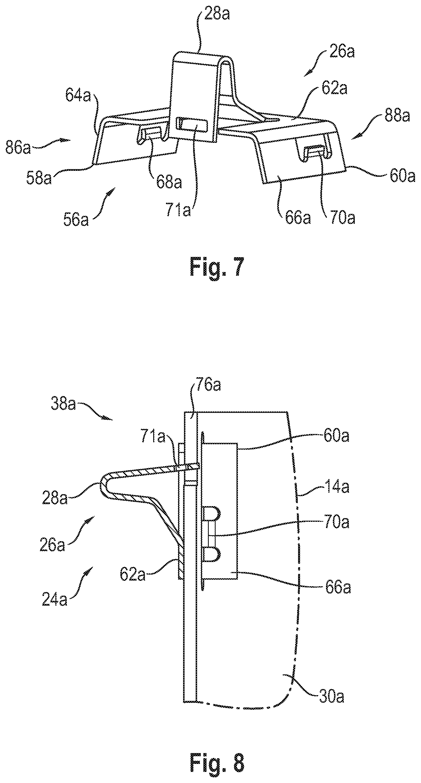
[0047] FIG. 7 is a perspective view showing the locking fixing element shown in FIG. 6;
[0048] FIG. 8 is a longitudinal sectional view of an inner housing with the locking fixing element according to FIGS. 6 and 7, which is carried thereon;
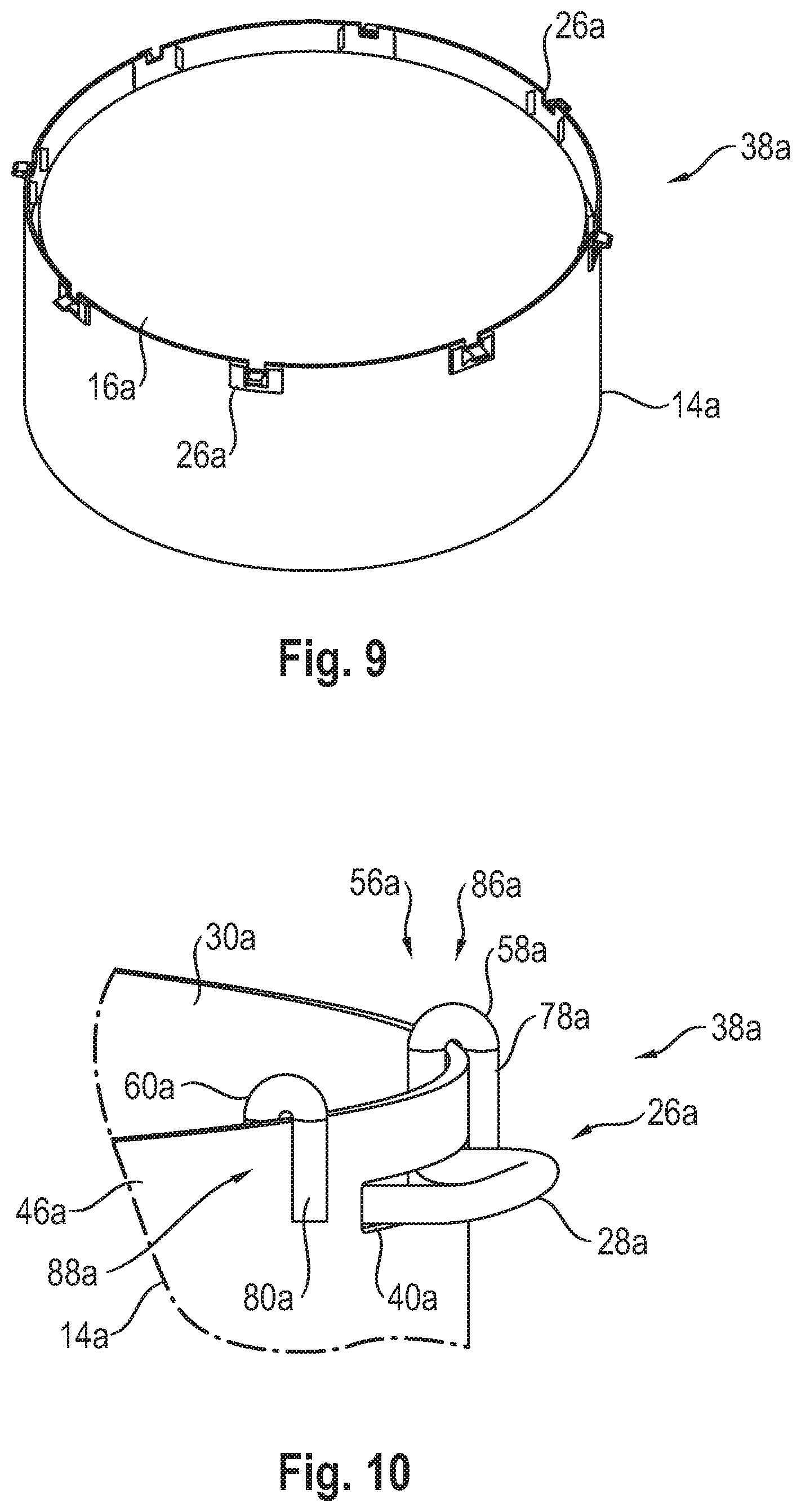
[0049] FIG. 9 is a perspective view of an inner housing with a locking fixing element according to FIGS. 6 through 8, which is provided thereon;
[0050] FIG. 10 is a cut away view showing a locking fixing element, which is provided as a shaped wire part, at an inner housing of an exhaust gas treatment assembly unit;
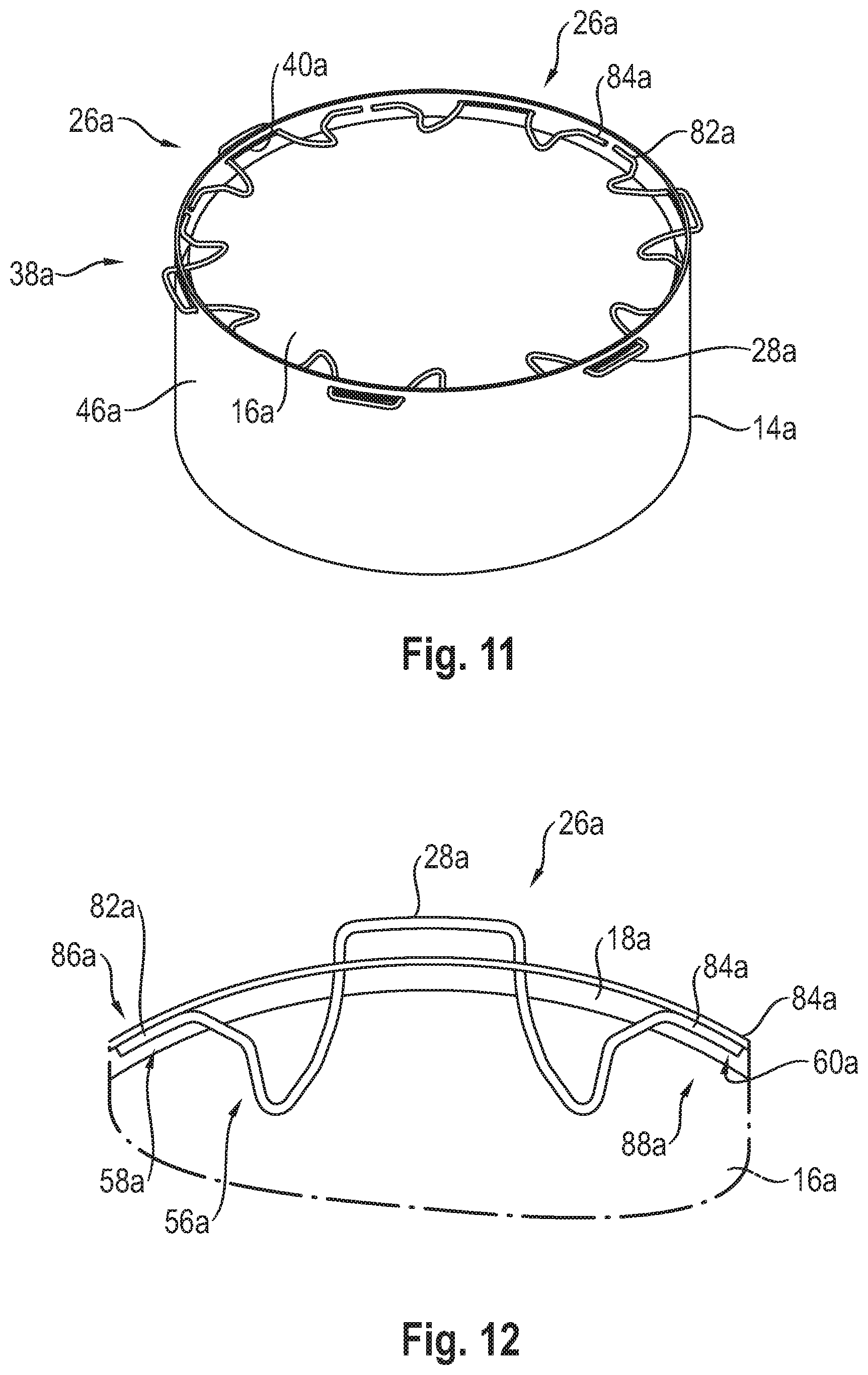
[0051] FIG. 11 is a perspective view of an inner housing of an exhaust gas treatment assembly unit with a plurality of locking fixing elements provided as shaped wire parts;
[0052] FIG. 12 is a cut away view showing a locking fixing element according to FIG. 11 at the inner housing;
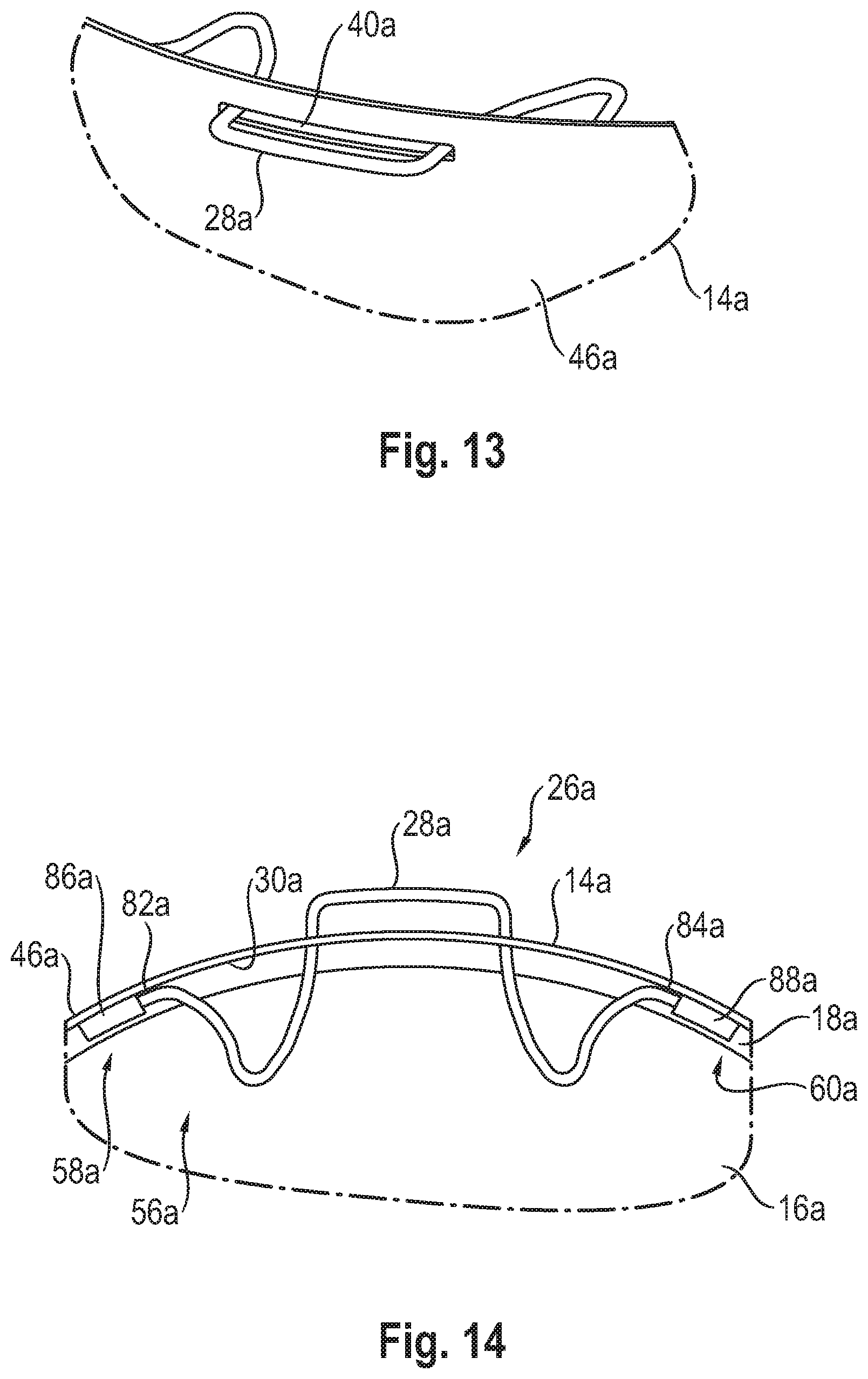
[0053] FIG. 13 is a cut away view showing the inner housing from an outer side with a locking fixing element according to FIGS. 11 and 12;
[0054] FIG. 14 is a cut away view showing, corresponding to the view of FIG. 12, an alternative type of connection of a locking fixing element to the inner housing;
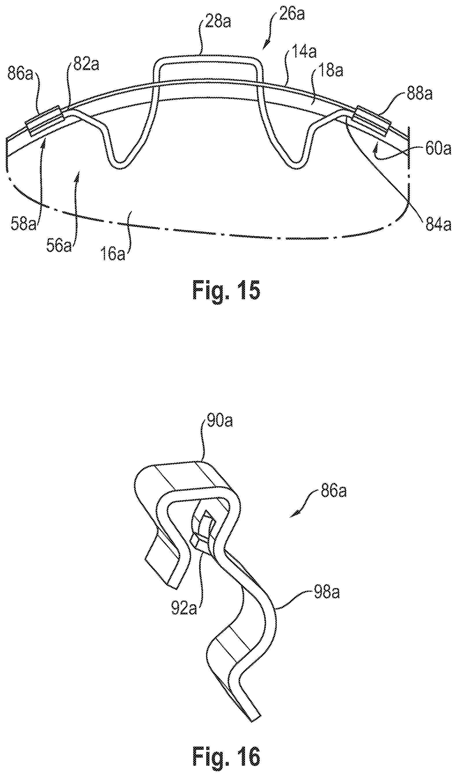
[0055] FIG. 15 is a view corresponding to FIG. 14 with another alternative type of connection of a locking fixing element to the inner housing;
[0056] FIG. 16 is a perspective view showing a holding element used in the embodiment according to FIG. 15 for connecting a locking element to the inner housing;
[0057] FIG. 17 is a partial longitudinal sectional view of the inner housing with a locking fixing element held at the inner housing by a holding element according to FIG. 16;
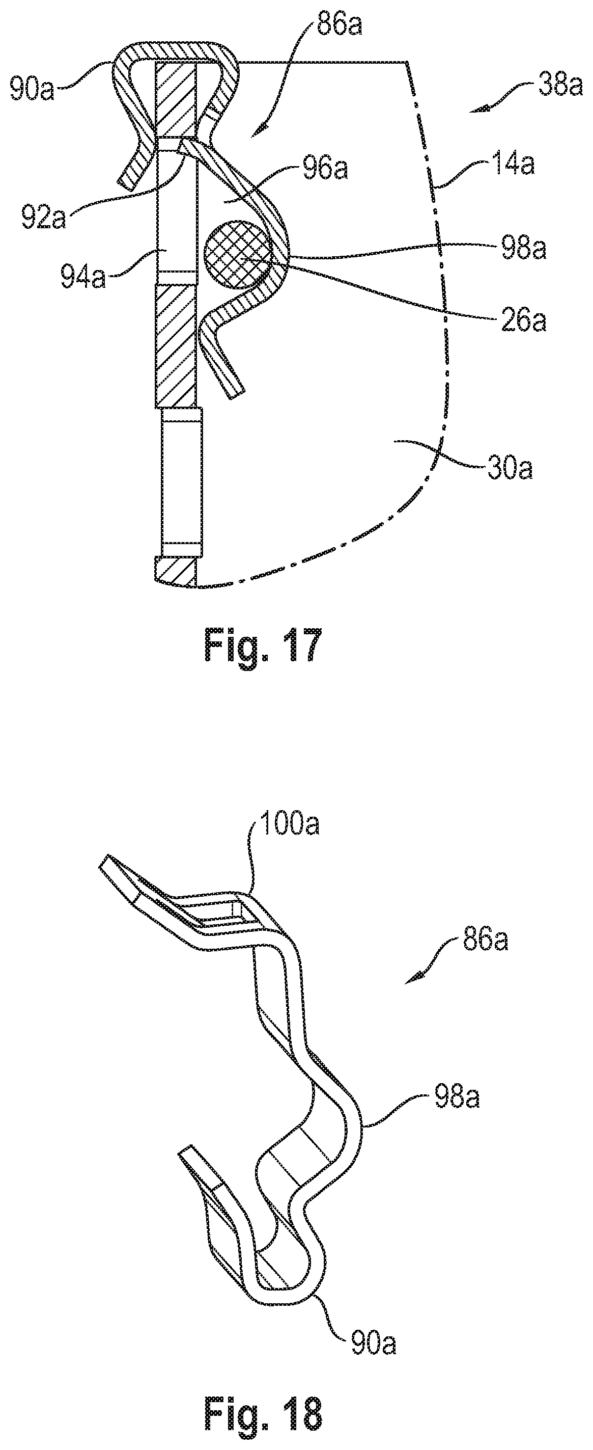
[0058] FIG. 18 is a perspective view showing an alternative embodiment of a holding element;
[0059] FIG. 19 is a partial longitudinal sectional view of the inner housing with a locking fixing element held at the inner housing by a holding element according to FIG. 18;
[0060] FIG. 20 is a cut away view showing an alternative embodiment of a locking fixing element configured as a shaped wire part;
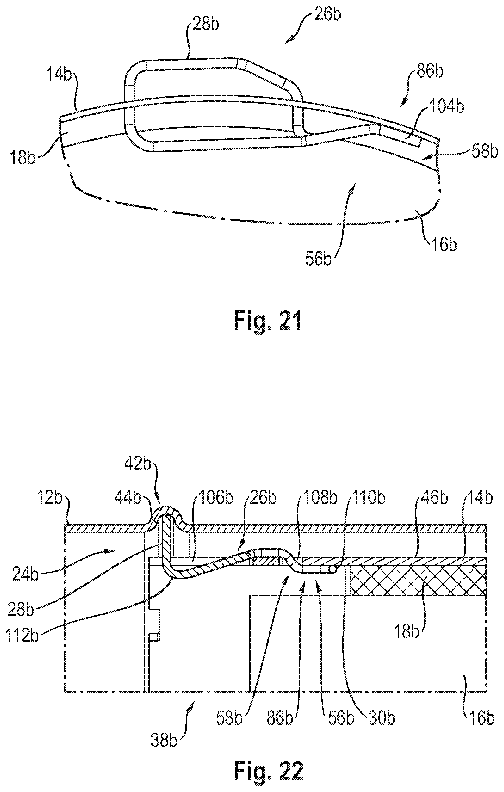
[0061] FIG. 21 is an axial cut away view showing a locking fixing element according to FIG. 20, which is arranged at the inner housing;
[0062] FIG. 22 is a partial sectional view showing an inner housing held at an outer housing of an exhaust gas treatment assembly unit by an alternative configuration of locking fixing elements provided as a shaped wire part;
[0063] FIG. 23 is a perspective view showing a locking fixing element that can be used in the embodiment according to FIG. 22;
[0064] FIG. 24 is a perspective view showing another locking fixing element that can be used in the embodiment according to FIG. 22;
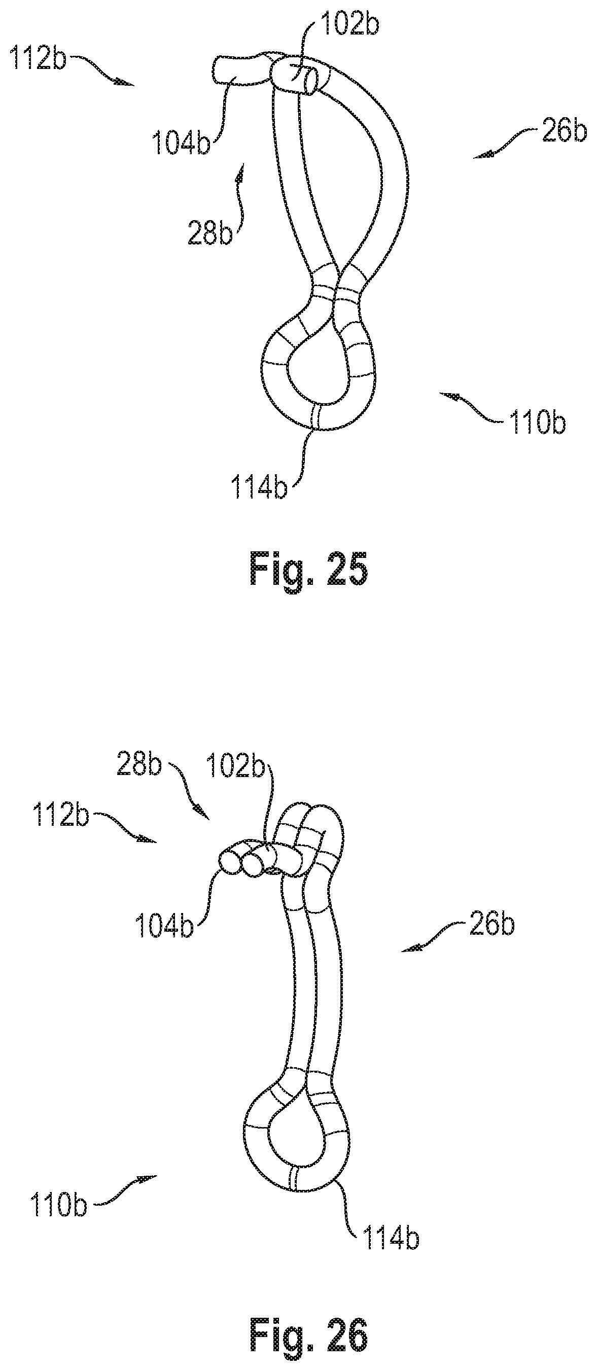
[0065] FIG. 25 is a perspective view showing another locking fixing element that can be used in the embodiment according to FIG. 22
[0066] FIG. 26 is a perspective view showing another locking fixing element that can be used in the embodiment according to FIG. 22;
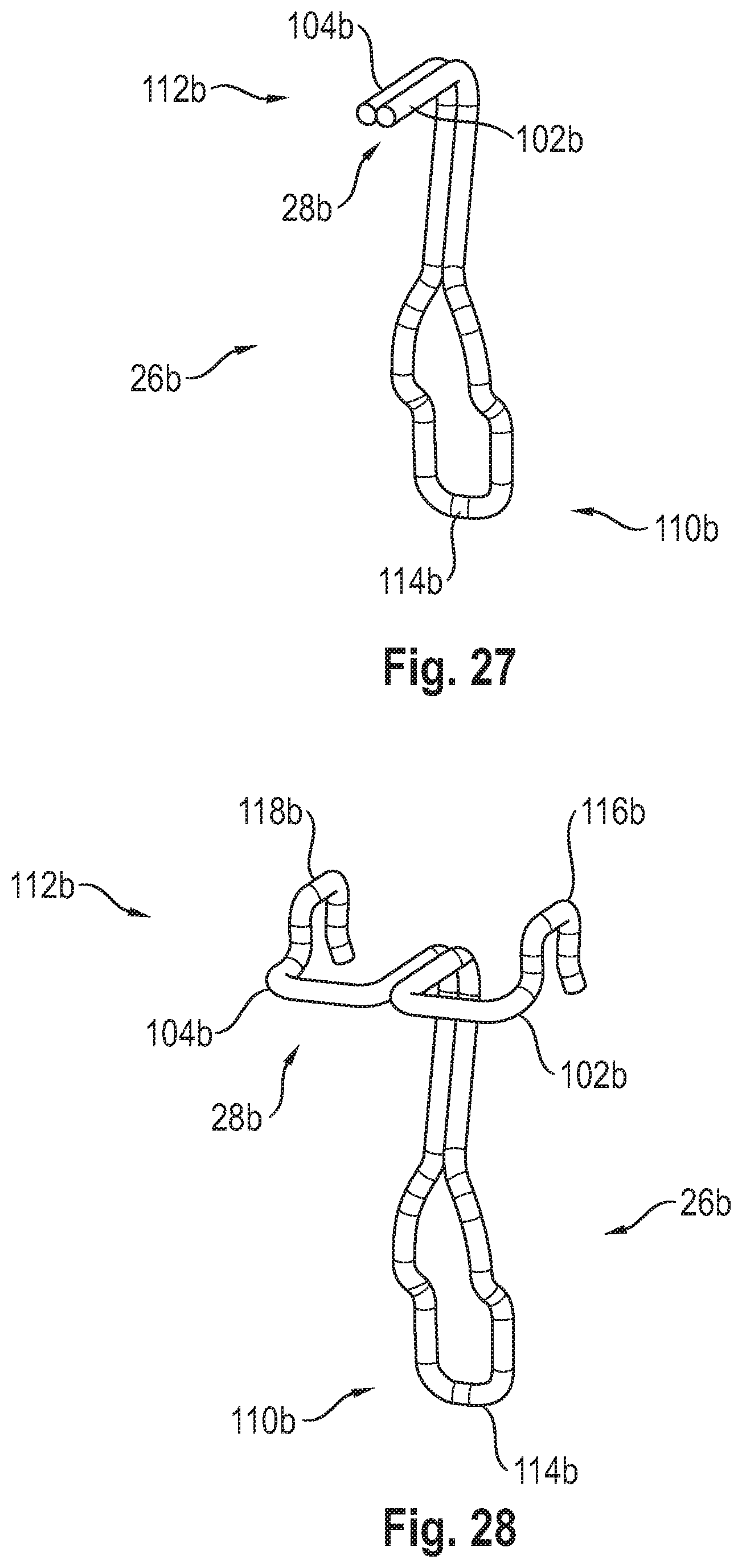
[0067] FIG. 27 is a perspective view showing another locking fixing element that can be used in the embodiment according to FIG. 22;
[0068] FIG. 28 is a perspective view showing another locking fixing element that can be used in the embodiment according to FIG. 22;
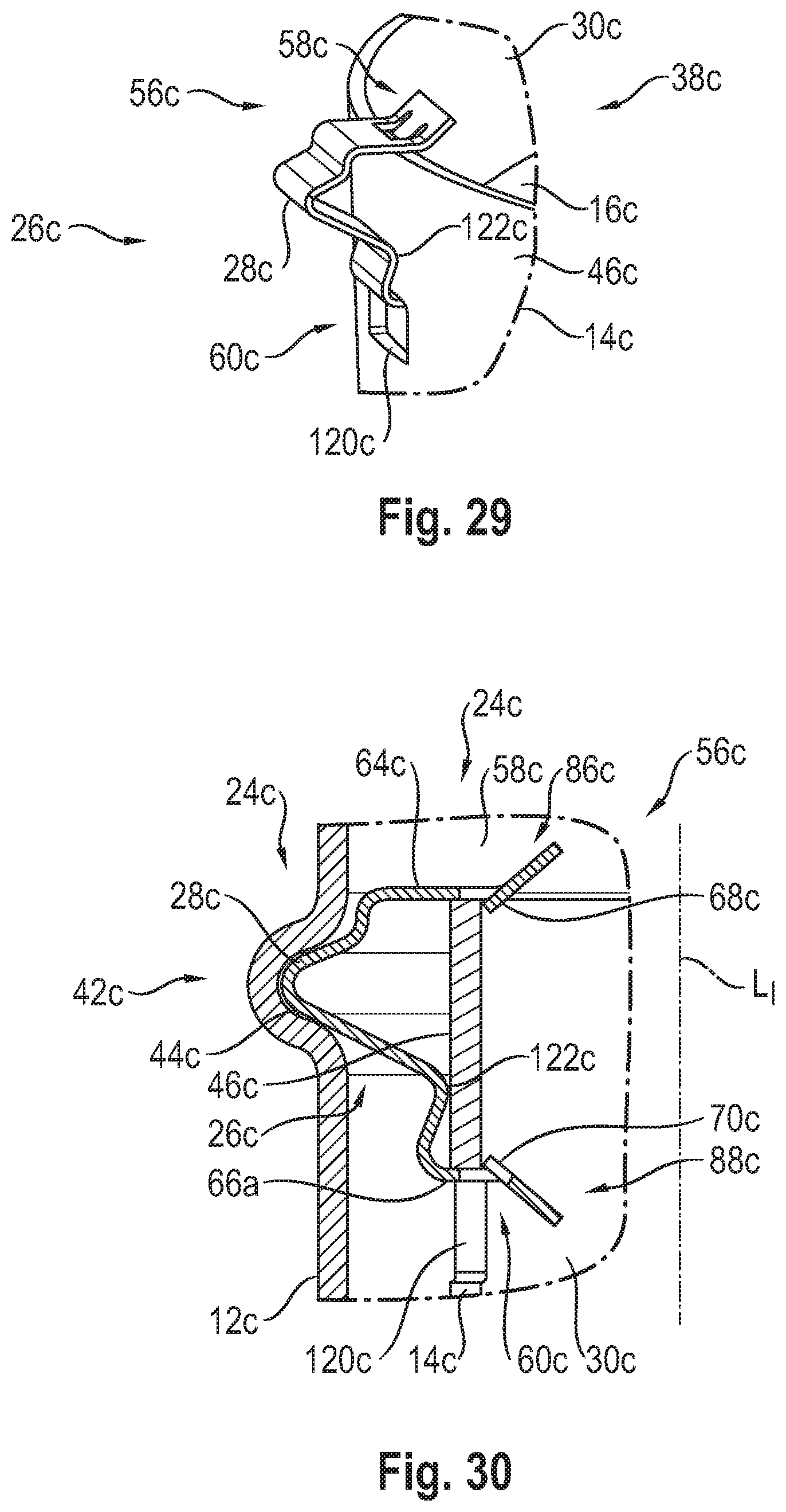
[0069] FIG. 29 is a cutaway perspective view showing an alternative embodiment of a locking fixing element that is fixed at an inner housing and is provided as a shaped sheet metal part;
[0070] FIG. 30 is a partial sectional view showing an inner housing held by a locking fixing element according to FIG. 29 at an outer housing of an exhaust gas treatment assembly unit;
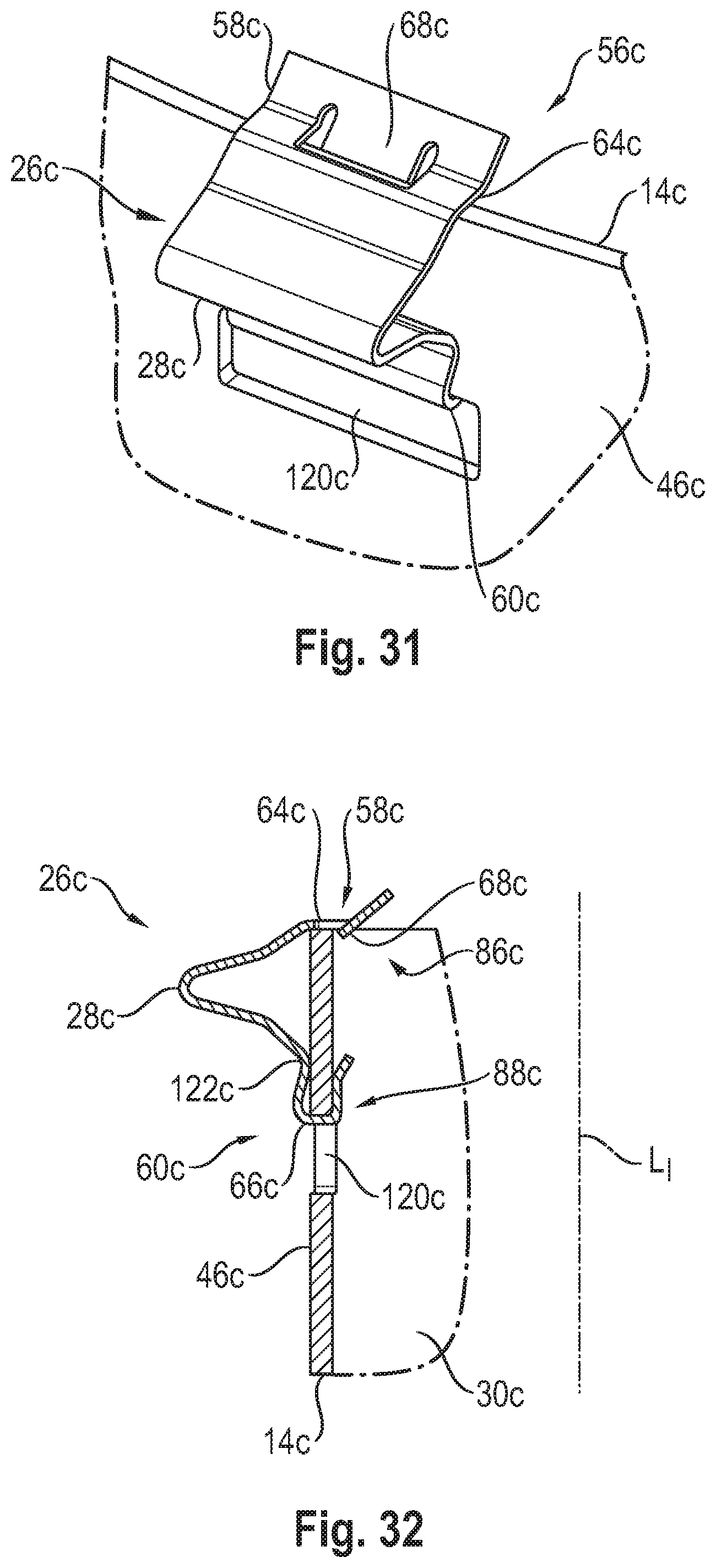
[0071] FIG. 31 is a cutaway perspective view showing an alternative embodiment of a locking fixing element held at an inner housing;
[0072] FIG. 32 is a partial longitudinal sectional view of the locking fixing element according to FIG. 31, which is held at the inner housing;
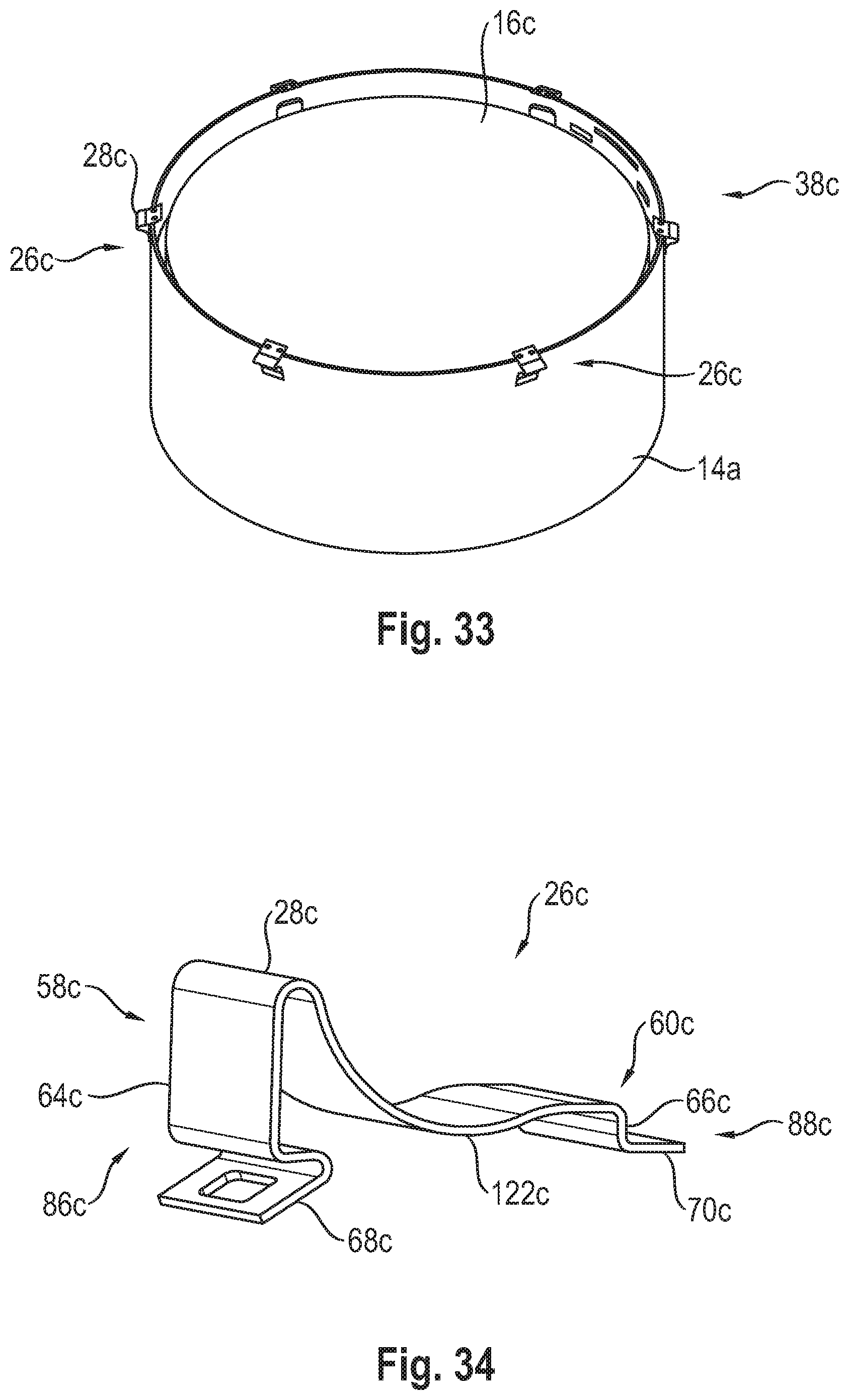
[0073] FIG. 33 is a perspective view showing the inner housing with a plurality of locking fixing elements provided as shaped sheet metal parts;
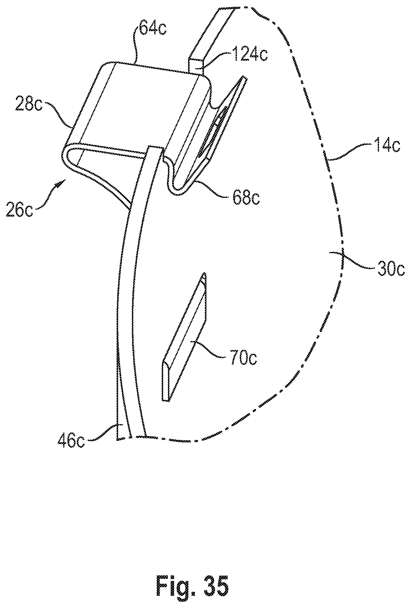
[0074] FIG. 34 is a perspective view showing another embodiment of a locking fixing element configured as a shaped sheet metal part; and
[0075] FIG. 35 is a cutaway perspective view showing a locking fixing element according to FIG. 34, which is held at an inner housing of an exhaust gas treatment assembly unit.
DESCRIPTION OF PREFERRED EMBODIMENTS
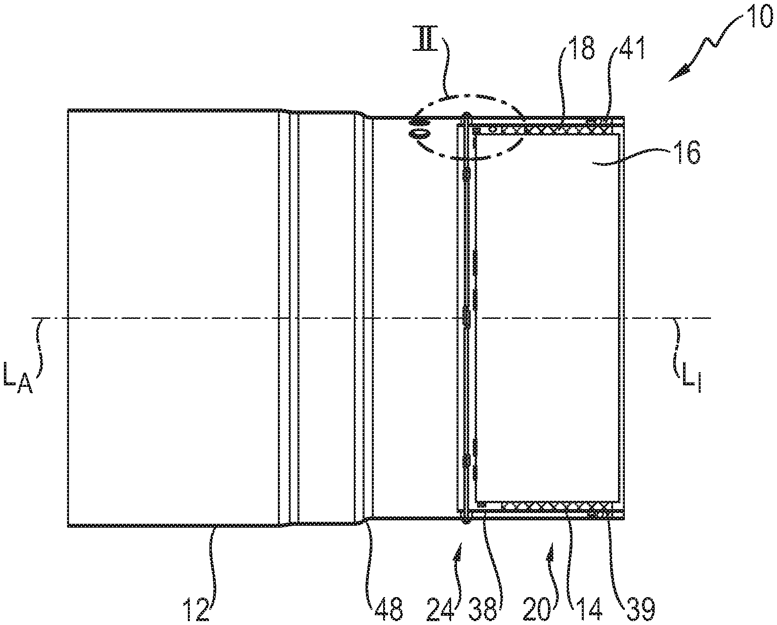
[0076] Referring to the drawings, FIG. 1 shows in a longitudinal section an exhaust gas treatment assembly unit, generally designated by 10, for an exhaust system of an internal combustion engine in a vehicle. The exhaust gas treatment assembly unit 10 comprises a tubular outer housing 12, which is made, for example, of a sheet metal material and is elongated in the direction of an outer housing longitudinal axis L.sub.A. The exhaust gas treatment assembly unit 10 further comprises a tubular inner housing 14, which is likewise provided, for example as a shaped sheet metal part and is elongated in the direction of an inner housing longitudinal axis L.sub.I.
[0077] An exhaust gas treatment unit 16 is arranged and held in the inner housing 14. The exhaust gas treatment unit 16, configured, for example, as a catalytic converter, may comprise a monolith coated with catalytically active material and may be held in the inner housing 14 by a mounting mat 18 enclosing this exhaust gas treatment unit 16. The outer housing 12 may be closed by a deflecting housing in an axial end area 20 receiving the inner housing 14.
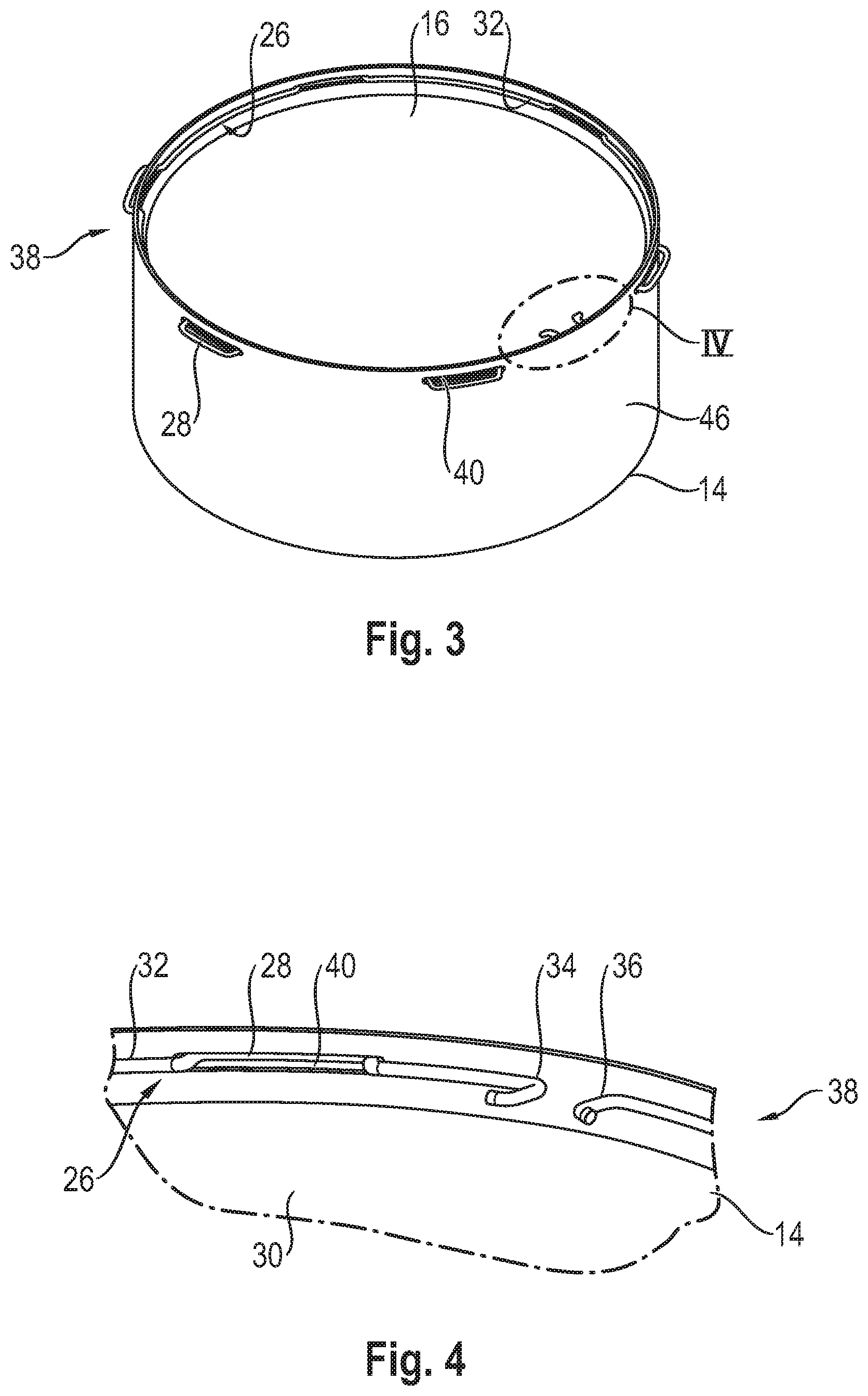
[0078] FIG. 2 shows more clearly how the inner housing 14 is supported by means of a locking fixing device generally designated by 24 at the outer housing 12. The locking fixing device 24 comprises a locking fixing element 26, which has a ring-shape configuration in this exemplary embodiment. The locking fixing element 26 is provided as a shaped wire part and has a plurality of locking meshing areas 28 following one another in the circumferential direction about the inner housing longitudinal axis L.sub.I. These locking meshing areas 28 provided with an essentially U-shaped form by bending a wire blank project radially outwards with respect to a ring body 32 of the locking fixing element 28. The ring body 32 is in contact with an inner side 30 of the inner housing 14 and extends about the inner housing longitudinal axis L.sub.I along the inner side 30 and is pressed, for example, by a prestress predefined by the shaping of the locking fixing element 26 against the inner side 30. As this is shown in FIGS. 3 and 4, the ring body 32 is open, i.e., it does not form a closed ring, so that this has two circumferential ends 34, 36, which are bent, for example, radially inwards, and which are located opposite each other with a small circumferential distance between two locking meshing areas 28. It should be noted that the two circumferential ends 34, 36 could also be connected to one another, for example, by welding, so that the ring body 32 may have basically a closed ring structure.
[0079] In association with each of the locking meshing areas 28, a passage opening 40, which is elongated in the circumferential direction at an axial end area 38 of the inner housing 14 and through which passes a respective locking meshing area 28, is provided at an axial end area 38 of the inner housing 14. The circumferential length of the passage openings 40 corresponds approximately to the circumferential length of the locking meshing areas 28, and an axial width of the passage openings 40 approximately corresponds to the thickness of the wire material of the locking fixing element 26, so that this is held in both axial directions and also in the circumferential direction in a defined manner at the inner housing 14.
[0080] In association with the locking fixing element 26 or its locking meshing areas 28, a locking receiving area designated by 42 is provided at the outer housing 12. The locking receiving area 42 may be provided by a bead-like (bead) bulge directed radially outwards and it thus forms a groove-like (groove) locking depression 44 passing through preferably without interruption in the circumferential direction.
[0081] When the inner housing 14 already containing the exhaust gas treatment unit 16 is pushed into the outer housing 12, for example, from the open side of the outer housing 12, which open side can be seen, for example, from the left-hand part of FIG. 1, the locking meshing areas 28, which are basically prestressed radially outwards and thus project radially over an outer side 46 of the inner housing 14, are displaced radially inwards during the movement over a bevel 48 that reduces the diameter of the outer housing 12. If the inner housing 14 is displaced farther in the direction of the end area 20 of the outer housing 12, the locking meshing areas 28 become aligned axially with the locking depression 44 and snap into this based on the inherent prestress of the locking fixing element 26. As a result, the inner housing 14 and hence also the exhaust gas treatment unit 16 being carried on this are held by the locking effect at the outer housing 12 in a stable manner and securely. Due to the force acting axially in the opposite direction, the locking meshing areas 28 are displaced radially inwards at the edge areas of the locking depression 44, so that the locking effect can be abolished and the inner housing 14 can be pushed again out of the outer housing 12 together with the exhaust gas treatment unit 16.
[0082] It should be noted that when, for example, the axial end area 20 of the outer housing 12 is not closed by a deflecting housing, the inner housing 14 can, of course, also be pushed into the outer housing 12 from this axial side.
[0083] Stable holding of the inner housing 14 in the outer housing 12 may further be supported by arranging mounting material 41, for example, wire material, for example, wire mesh or the like, between the inner housing 14 and the outer housing 12 at least in the other axial end area 39 of the inner housing 14. This mounting material 41 may be held under compression between the inner housing 14 and the outer housing 12, so that it supports the inner housing radially with respect to the outer housing 12 especially in the axial end area 39 of the inner housing 14 and it also transmits, moreover, a holding force acting in the axial direction between the inner housing 14 and the outer housing 12. The inner housing 14 is thus held in a stable manner in its two axial end areas 38, 39 both in the radial direction and in the axial direction with respect to the outer housing 12. The essential holding effect in the axial direction or/and in the radial direction can be provided here by the mounting material 41, while the locking fixing device 24 may have essentially the function of fixing and hence predefining a defined axial positioning of the inner housing 14 with respect to the outer housing 12.
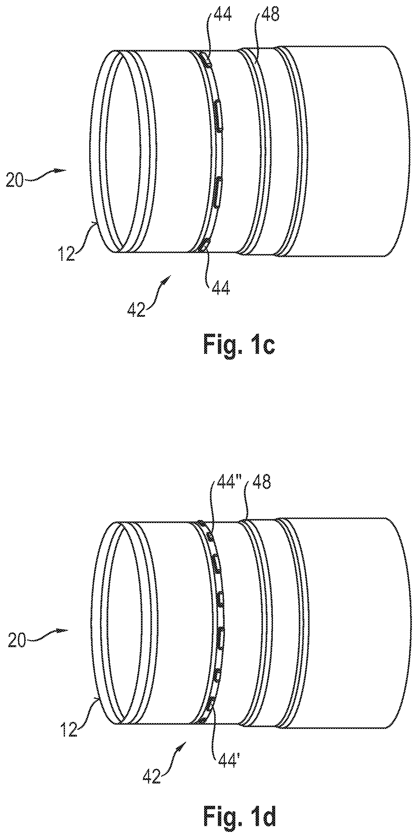
[0084] FIGS. 1a-1d show different embodiments of the outer housing 12. FIG. 1a shows the embodiment already described above with reference to FIGS. 1 and 2, in which the locking receiving area 42 has a locking depression 44 passing through without interruption in the circumferential direction.
[0085] In the outer housing 12 shown in FIG. 1b, the locking receiving area 42 does not comprise a groove locking depression 44 passing through in the circumferential direction, but a locking depression 44, which is interrupted at least in a circumferential area, is open radially inwards and is formed by an outwardly formed bulge of the outer housing 12. It should be noted that a plurality of circumferential interruptions, for example, two circumferential interruptions, may also be provided, so that two longer areas of the locking depression 44, which areas extend in the circumferential direction, or a plurality of longer locking depressions 44 following one another in the circumferential direction may correspondingly be present.
[0086] A plurality of locking depressions 44, which follow one another in the circumferential direction and are open radially inwards, are provided in the embodiment of the outer housing, which embodiment is shown in FIG. 1c. For example, such a locking depression 44, which is limited in the circumferential direction and corresponds, for example, in terms of its circumferential extension to the circumferential width of a respective locking meshing area 28, may be provided in association with each locking fixing element at the inner housing 14. A defined rotational positioning of the inner housing 14 with respect to the outer housing 12 may also be predefined in this manner by the locking effect of the locking fixing device 24. Each of the locking depressions 44 shown in FIG. 1c has essentially the same circumferential extension. Further, all the locking depressions 44 located directly adjacent to one another in the circumferential direction may have the same circumferential distance from one another.
[0087] FIG. 1d shows an embodiment in which locking depressions 44' with a greater circumferential extension and locking depressions 44'' with shorter circumferential extension are arranged in a mutually alternating manner. Corresponding to these locking depressions 44', 44'' with different circumferential extensions, the locking meshing areas 28 of the locking fixing elements 26 provided at the inner housing 14 may have different circumferential extensions, so that a defined positioning of the inner housing 14 in the outer housing 12 is further supported.
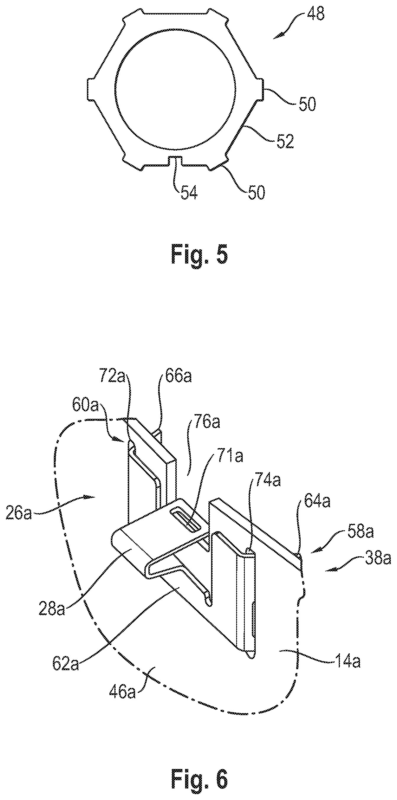
[0088] FIG. 5 shows a tool 48, which can be used to bring a wire blank to the shape suitable for insertion into the inner housing 14. It is seen that in association with the locking meshing areas 28 to be provided at the locking fixing element 26, the tool 48 has radially outwards projecting projections 50 which predefine the shape of the locking meshing areas 28. In the exemplary embodiment of the tool 48 shown in FIG. 5, the edge areas 52 extending between two projections 50 have a configuration in which they extend essentially straight, so that the wire blank, which is to be wound around the outer circumference of the tool 50 and is to be adapted to the shape thereof, will also have between two locking meshing areas 28 to be formed thereon an essentially straight extension, which will consequently extend at a spaced location from the inner side 30 of the inner housing 14. Different shape specifications can, of course, be provided here for the tool 50 and hence also for the ring body 32 of the locking fixing element 26, which ring body 32 is to be embodied with it. In association with the circumferential ends 34, 36, which are to be shaped radially inwards, a recess 54 receiving these ends is provided on the tool 50.
[0089] Different alternative embodiments of an exhaust gas treatment assembly unit and of the locking fixing device fixing the inner housing at the outer housing will be described below with reference to FIGS. 6 through 19. Components that correspond to above-described components in terms of configuration and function are described with the same reference numbers with a suffix "a" added. It should be noted that the basic configuration of the outer housing and of the inner housing containing the exhaust gas treatment unit may be such as described above with reference to FIGS. 1 through 4.
[0090] In the embodiments of a locking fixing device 24a, which will be described below, this locking fixing device comprises a plurality of locking fixing elements 26a, which are arranged at spaced locations from one another in the circumferential direction about the inner housing longitudinal axis L.sub.I, and are held or fixed at the inner housing 14a. All the locking fixing elements 26 to be fixed at the inner housing 14a have preferably but not necessarily an identical design in each of the embodiments described below.
[0091] A first embodiment of such locking fixing elements 26a is shown in FIGS. 6 through 9. Each locking fixing element 26a is configured as a shaped sheet metal part in this embodiment. The locking fixing element 26a has a holding area generally designated by 56a, with which this is held at the housing in the manner described below. Further, the locking fixing element 26a has a locking meshing area 28a, which is provided, for example, by correspondingly bending a sheet metal strap and which projects radially outwards with respect to the holding area 56a, and which can mesh with the locking depression at the outer housing, which said locking depression is described above with reference to FIG. 1, when the locking fixing element 26a is held at the inner housing 14a.
[0092] The holding area 56a has two holding sections 58a, 60a, which receive the locking meshing area 28a between them and enter into a holding interaction with the inner housing 14a. Each of these holding sections 58a, 60a is provided by a holding leg 64a, 66a bent radially inwards from a central area 62a, which also carries the locking meshing area 28a. A holding projection 68a, 70a bent in the direction away from the locking meshing area 28a is provided at each of the holding legs 64a, 66a.
[0093] In association with the two holding sections 58a, 60a, two passage openings 72a, 74a elongated essentially in the direction of the inner housing longitudinal axis L.sub.I are provided at the inner housing 14a at the axial end area thereof. One of the holding legs 64a, 66a passes through each of these passage openings 72a, 74a arranged at circumferentially spaced locations from one another, so that the central area 62a is in contact with the outer side 46a of the inner housing 14a and the holding projections 68a, 70a extend behind the inner housing 14a on the inner side 30a thereof.
[0094] Each of the locking fixing elements 26a, which can be seen in FIG. 9 and is arranged at circumferentially spaced locations from one another at the axial end area 38a of the inner housing 14a, is thus held in a stable manner at the inner housing 14a by the two holding sections 58a, 60a, which are arranged at circumferentially spaced locations from one another and receive the locking meshing area 28a between them, in such a manner that based on the shape of the respective locking meshing area 28a, this area can deflect radially when the inner housing 14a carrying the locking fixing elements 26a is pushed into the outer housing. Based on their inherent prestress, the locking meshing areas 28a deflect into the radially inwardly open locking depression at the outer housing and thus fix the inner housing 14a by a locking effect. In order to make this radial movement of the locking meshing areas 28a possible, an axially open recess 76a, into which the locking meshing area 28a provided with a U-shaped form can deflect with the free U-leg thereof, can be provided at the axial end area 38a of the inner housing 14a in association with each of the locking fixing elements 26a.
[0095] To sever the locking meshing of the locking meshing area 28a of the locking fixing element 26a or of each locking meshing element 26a, a tool, for example, a screwdriver or the like, can be used to mesh with a tool insertion opening 71a provided at the free U-leg of the locking meshing area 28a having a U-shaped configuration. Even though this tool insertion opening 71a is positioned radially in the area of the wall of the inner housing 14a, this access is possible via the axially open recess 76a. By pulling radially inwards, the locking meshing area 28a or each locking meshing area 28a can be pulled out of the locking receiving area, which received this before.
[0096] FIG. 10 shows a locking fixing element 26a provided as a shaped wire part. This has a U-shaped locking meshing area 28a passing through a corresponding passage opening 40a in the axial end area 38a of the inner housing 14a. The locking meshing area is adjoined in the circumferential direction on both sides of the locking meshing area 28a by the holding sections 58a, 60a of the holding area 56a. Each of the holding sections 58a, 60a comprises an end section 78a, 80a of the locking fixing element 26a, which said end section is bent in the shape of a U and which extends around the inner housing 14a at its axial end area 38a from radially inwards to radially outwards.
[0097] It should be noted that, of course, a plurality of locking fixing elements 26a arranged following one another in the circumferential direction are also provided at the inner housing 14a in such a configuration of the locking fixing element 26a. It can especially be seen that the passage openings 40a provided at the inner housing 14 can be used in this connection, which passage openings may also be used, for example, for receiving the ring-shape locking fixing element 26 that can be seen in FIG. 3. Depending, for example, on the intended use, the inner housing 14 or 14a configured with respective passage openings 40 and 40a elongated in the circumferential direction may be equipped either with the ring-shape locking fixing element 26 that can be seen in FIG. 3 and FIG. 4 or with a plurality of the locking fixing elements 26a shown in FIG. 10.
[0098] Another embodiment of a locking fixing device 24a, which can use such passage openings 40a elongated in the circumferential direction at the axial end area 38a of the inner housing 14a, is shown in FIGS. 11 through 13. Each of the plurality of locking fixing elements 26a arranged following one another in the circumferential direction is provided in this embodiment again as a shaped wire part. The locking meshing area 28a, which has a U-shaped configuration and with which each locking fixing element 26a passes through the associated passage opening 40a from radially inwards to radially outwards, is provided in an area that is a central area in the circumferential direction, so that the locking meshing area 28a projects radially on the outer side 46a of the inner housing 14a.
[0099] The two holding sections 58a, 60a of the holding area 56a are provided on both sides of the locking meshing area 28a by respective circumferential ends 82a, 84a of the locking fixing element 26a. The locking fixing element 26a is fixed in each of these circumferential ends 82a, 84a by connection in substance, for example, by welding on the inner side 30a of the inner housing 14a.
[0100] FIG. 11 shows that a ring-shape structure, in which the respective circumferential ends 82a, 84a of adjacent locking fixing elements 26a are located opposite each other in the circumferential direction between two locking meshing areas 28a following one another in the circumferential direction or between passage openings 40a receiving these, is basically obtained with the plurality of locking fixing elements 26a following one another in the circumferential direction. Such a structure could also be provided, for example, with a single locking fixing element, as this was described above with reference to FIGS. 1 through 4.
[0101] In the embodiments described above with reference to FIGS. 6-13, the locking fixing elements 26a in the respective holding sections 58a, 60a have holding elements 86a and 88a, respectively, which are configured integrally at the locking fixing elements 26a. These are provided in the exemplary embodiment according to FIGS. 6-9 essentially by the holding legs 64a, 66a. The U-shaped end sections 78a, 80a provided in the holding sections 58a, 60a provide the holding elements 86a, 88a configured integrally with the locking fixing element 26a in the exemplary embodiment according to FIG. 10. In the exemplary embodiment according to FIGS. 11-13, the circumferential ends 82a, 84a provide these holding elements 86a, 88a configured integrally with the locking fixing element 26a.
[0102] Embodiments in which the holding elements 88a are provided as separately configured components on a respective locking fixing element 26a will be described below.
[0103] A variant of the embodiment described above with reference to FIGS. 11 through 13 is shown in FIG. 14. The locking fixing element 26a or each locking fixing element 26a is not fixed directly with its circumferential ends 82a, 84a at the inner housing 14a in this embodiment. Rather, sleeve-like (sleeve) holding elements 86a, 88a, into which a respective circumferential end 82a, 84a is inserted, are provided, for example, in association with each of the circumferential ends 82a, 84a or with each holding section 58a, 60a. The holding elements 86a, 88a may be fixed by connection in substance, for example, by welding, on the inner side 30a of the inner housing 14a. It is possible now to proceed, for example, such that the sleeve holding elements 86a, 88a are fixed at first at the inner housing 14a in the circumferential direction on both sides of a respective passage opening 40a and the locking meshing element 26a, which is basically elastically deformable due to being made of a wire material, is passed with its locking meshing area 28a through the associated passage opening 40a and the two circumferential ends 82a, 84a are inserted in the circumferential direction into openings formed in the holding elements 86a, 88a and are held therein by circumferential prestress. As an alternative, the circumferential ends 82a, 84a may be received at first in the holding elements 86a, 88a, for example, by means of press fit. The locking fixing element 26a equipped with the holding elements 86a, 88a can then be brought closer to the inner housing 14a from the radially inner direction, and, after the locking meshing area 28a had been passed through the associated passage opening 40a, the two holding elements 86a, 88a can be fixed on the inner side 30a of the inner housing 14a.
[0104] FIGS. 15 through 17 show another embodiment, in which a locking fixing element 26a provided as a shaped wire part is fixed in the two holding sections 58a, 60a of the holding area 56a by the use of two holding elements 86a, 88a at the inner housing 14a. Each of these holding elements 86a, 88a is provided as a shaped sheet metal part, as is shown especially in FIG. 16 on the basis of the holding element 86a. The holding element 86a has an approximately U-shaped fixing area 90a, which extends over the inner housing 14a in the axial end area 38a thereof and with which the holding element 86a is pushed axially over the inner housing 14a. In association with the U-shaped fixing area 90a, a fixing projection 92a is provided, which projects into this fixing area 90a and which enters an associated fixing recess 94a formed in the inner housing 14a when the holding element 86a is pushed axially on and thus ensures a stable fixing of the holding element 86a at the axial end area 38a of the inner housing 14a.
[0105] Starting from the approximately U-shaped or .OMEGA.-shaped fixing area 90a, the holding element 86a has an arc-shaped receiving area 98a. As this is illustrated in FIG. 7, the arc-shaped receiving area 98a forms, together with the inner housing 14a, a receiving opening 96a, into which the circumferential end 82a of the locking fixing element 26a can be pushed in the circumferential direction. FIG. 17 illustrates in this connection by the mutually intersecting contours of the receiving area 98a and of the circumferential end 82a that the receiving area 98a is shaped basically such that the radial width of the receiving opening 96a is smaller than the thickness of the wire material of the locking fixing element 26a, so that the locking fixing element 26a is pressed with its circumferential end 82 by the arc-shaped receiving area 98a against the inner side 30a of the inner housing 14a.
[0106] An alternative embodiment of a holding element 86a provided as a shaped sheet metal part is shown in FIGS. 18 and 19. The holding element 86a has again a U-shaped or .OMEGA.-shaped fixing area 90a, which is not pushed over an axial end of the inner housing 14a in this embodiment, but is positioned such that it meshes with a fixing recess 94a provided at a spaced location from the axial end of the inner housing 14a, so that the holding element 86a passes basically through the inner housing 14a in the area of the fixing recess 94a from radially inwards and extends over and behind it on its outer side 46a. The fixing area 90a is adjoined again by the arc-shaped receiving area 98a. This arc-shaped receiving area 98a is joined by another fixing section 100a extending over the axial end of the inner housing 14a radially outwards. A fixing projection 93a extending over the inner housing 14a on its outer side 46a is formed at this fixing section 100a, so that the holding element 86a passes through and extends over the inner housing 14a in this embodiment in two axial areas, axially on both sides of the receiving area 98a from radially inwards to radially outwards, and it extends behind it on its outer side. As a result, very stable holding is guaranteed at the inner housing 14a.
[0107] With reference to FIGS. 20 through 28, the following embodiments of the locking fixing device will be described, in which a plurality of locking fixing elements following one another in the circumferential direction are used again, but these are not fixed on both sides of a respective locking meshing area at the inner housing. Rather, each locking fixing element is shaped in the embodiments described with reference to FIGS. 20 through 28 such that the holding area comprises only a single holding section, which is arranged either on a circumferential side or on an axial side with respect to the respective locking meshing area provided at this locking fixing element. Components that correspond in terms of configuration and function to components and embodiments described above are designated by the same reference numbers to which the suffix "b" is added.
[0108] FIGS. 20 and 21 show a locking fixing element 26b, which is provided as a shaped wire part and which is positioned again with its locking meshing area 28b having an essentially U-shaped configuration such that it passes again through a passage opening 40b provided in the axial end area 38b of the inner housing 14b from radially inwards to radially outwards. The locking fixing element 26b provided as a shaped wire part is shaped such that the end legs 102b, 104b thereof are positioned such that they are located, for example, adjacent to one another in the axial direction on a circumferential side with respect to the locking meshing area 28b. The locking fixing element 26b can be fixed with these two end legs 102b, 104b on the inner side 30b of the inner housing 14b by connection in substance, for example, by welding. Based on the elasticity of the wire material, of which the locking fixing element 26b is made, this can deflect radially inwards with its locking meshing area 28b when the inner housing 14b equipped with a plurality of such locking fixing elements 26b is pushed into the outer housing. These locking meshing areas 28b can then also snap again into the locking depression provided on the outer housing and thus ensure fixing of the inner housing 14b on the outer housing.
[0109] In this embodiment, the holding area 56b forms with the two end legs 102b, 104b providing the holding section 58b thereof a holding element 86b configured integrally with the locking fixing element 26b, with which, extending beyond the locking meshing area 28b, which passes through the passage opening 40b and is thus held in both axial directions, the locking fixing element 26b is fixed at the inner housing 14b in both axial directions by connection in substance.
[0110] An alternative embodiment to this is shown in FIG. 22. The inner housing 14b positioned in the outer housing 12b with the exhaust gas treatment unit 16b carried therein is seen. A recess 106b, which is, for example, open axially, is provided in the axial end area 38b of the inner housing 14b for the locking fixing element 26b, which is provided again as a shaped wire part. With a holding section 58b of the holding area 56b, which said holding section is bent in an approximately S-shaped form, the locking fixing element 26b passes through an additional recess 108b provided in the inner housing 14b from radially outwards to radially inwards and is supported with an axial end area 110b thereof on the inner side 30b of the inner housing 14b. For example, the locking fixing element 26b can be fixed with its axial end area 110b on the inner side 30b of the inner housing 14b by connection in substance, for example, by welding. In this case as well, the holding area 56b with the bent holding section 58b passing through the inner housing 14b forms a holding element 86b made integrally in one piece with the locking fixing element 28b, with which the locking fixing element 26b is fixed at the inner housing 14b in both axial directions.
[0111] In its other axial end area 112b, the locking fixing element 26b forms the radially outwards projecting locking meshing area 28b, which fixes the inner housing 14b at the outer housing 12b by meshing with the locking depression 44b on the outer housing 12b, prestressed radially outwards.
[0112] FIGS. 23 through 28 show different embodiments for such locking fixing elements provided as shaped wire parts. All these locking fixing elements 26b are shaped such that the end legs 102b, 104b of the locking fixing element 26b are located next to one another in the end area 112b, in which the locking meshing area 28b is also formed, and they are firmly connected to one another, for example, by connection in substance. The locking fixing element 26b forms in the end area 110b an arc 114b, which can be supported on the inner side 30b of the inner housing 14b.
[0113] FIGS. 23 through 28 show that in the same configuration, the shape of the locking fixing element 26b or of each locking fixing element 26b may be different both in the end area 110b and in the end area 112b as well as in the length area connecting these two end areas. Thus, as is shown, for example, in FIG. 25, the two end legs 102b, 104b may be shaped such that their free ends are bent away from one another in the circumferential direction, so that, unlike, for example, in the embodiments according to FIGS. 23, 24, 26 and 27, these end legs 102b, 104b can be positioned such that they mesh with the locking depression in areas formed with a curved outer circumferential contour rather than with their obtuse ends.
[0114] At the locking fixing element 26b shown in FIG. 28, the end legs 102b, 104b may additionally have U-shaped end sections 116b, 118b, with which they can extend over the axial end of the inner housing 14b radially inwards.
[0115] FIGS. 29 through 35 show embodiments of a locking fixing device, in which a plurality of locking fixing elements arranged following one another in the circumferential direction are provided as shaped sheet metal parts. Components that corresponds to above-described components in terms of configuration and function are designated with the same reference numbers with the addition of a suffix "c."
[0116] FIGS. 29 and 30 show a locking fixing element 26c, whose holding area 56c has two holding sections 58c, 60c arranged at axially spaced locations with respect to the inner housing longitudinal axis L.sub.I. In each of the holding sections 58c, 60c, the locking fixing element 26c extends over and passes through the locking fixing element 26c of the inner housing 14c from the outer side 46c thereof radially inwards. The holding leg 64c of the holding section 58c extends here over the axial end of the inner housing 14c in the axial end area 38c and extends behind the inner housing 14c on the inner side 30c thereof with an axially bent-off holding projection 68c.
[0117] With its holding leg 66c, the locking fixing element 26c passes through a passage opening 120c in the inner wall 14c and extends with a holding projection 70c behind the inner housing 14c on the inner side 30c thereof. The locking fixing element 26c provided as a shaped sheet metal part made of a sheet metal material may be shaped basically such that the two holding legs 64c, 66c are prestressed in the direction towards one another, so that the two holding projections 68c, 70c are held such that they extend reliably behind the inner housing 14c on the inner side 30c thereof.
[0118] The radially outwards projecting locking meshing area 28c, which is positioned such that it meshes with the locking depression 44c of the locking receiving area 42c, is formed axially between the two holding sections 58c, 60c. To make it possible to hold the locking meshing area 28c such that, prestressed radially outwards, it meshes with the locking depression 44c, a support section 122c supported radially inwards on the outer side 46c of the inner housing 14c is formed between the locking meshing area 28c and the holding section 60c.
[0119] If the inner housing 14c equipped with such locking fixing elements 26c is pushed into the outer housing 12c, the locking fixing element 26c supported with its support section 122c on the outer side 46c of the inner housing 14c can be displaced radially inwards with its locking meshing area 28c based on its inherent elasticity, and the holding leg 64c extending radially over the axial end of the inner housing 14c can likewise be displaced radially inwards, so that the holding projection 68c can temporarily be lifted off from the inner side 30c of the inner housing 14c. If the locking meshing area 28c snaps into the locking depression 44c of the locking receiving area 42c, this and together with this also the holding leg 64c are displaced again radially outwards, so that the holding projection 68c can again be in contact in the locked state, for example, with the inner side 30c of the inner housing 14c.
[0120] A modified embodiment of a locking fixing element 26c is shown in FIGS. 31 through 33. This differs from the embodiment shown in FIGS. 29 and 30 essentially in the shape of the holding section 60c passing through the passage opening 120c in the inner housing 14c. This holding section has an essentially U-shaped or .OMEGA.-shaped configuration and extends with its free leg behind the inner housing 14c on the inner side 30c thereof. FIG. 32 illustrates with mutually overlapping contour lines that the locking fixing element 26c is shaped such that the support section 122c adjoining the holding section 60c is held basically prestressed against the outer side 46c of the inner housing 14c.
[0121] Another embodiment of such a locking fixing element 26c provided as a shaped sheet metal part is shown in FIGS. 34 and 35. This locking fixing element 26c is shaped in its holding section 58c such that a holding projection 68c having an essentially U-shaped configuration, which extends behind the inner housing 14c on the inner side 30c thereof, is formed at the holding leg 64c. In association with the holding leg 64c, an axially open recess 124c is provided at the axial end area 38c of the inner housing 14c.
[0122] Adjoining the holding leg 66c, a holding projection 70c, which is bent in the direction away from the other holding section 58c and extends essentially axially, is formed at the holding section 60c, and said holding projection 70c, being in contact with the inner side 30c of the inner housing 14c, extends over and behind the inner housing 14c and thus forms an abutment for the support section 122c, which has an arc-shaped configuration and is in contact with the outer side 46c of the inner housing 14c and is prestressed against this outer side 46c.
[0123] The holding elements 86c, 88c provided essentially by the respective holding legs 64c, 66c are provided at a respective locking fixing element 26c as integral components, i.e., as components configured on one piece of material in the embodiments shown in FIGS. 29-35 as well, in which the locking fixing elements 26c are configured as shaped sheet metal parts.
[0124] While specific embodiments of the invention have been shown and described in detail to illustrate the application of the principles of the invention, it will be understood that the invention may be embodied otherwise without departing from such principles.
* * * * *
D00000
D00001
D00002
D00003
D00004
D00005
D00006
D00007
D00008
D00009
D00010
D00011
D00012

D00013
D00014

D00015
D00016
D00017
D00018
D00019
D00020
XML
uspto.report is an independent third-party trademark research tool that is not affiliated, endorsed, or sponsored by the United States Patent and Trademark Office (USPTO) or any other governmental organization. The information provided by uspto.report is based on publicly available data at the time of writing and is intended for informational purposes only.
While we strive to provide accurate and up-to-date information, we do not guarantee the accuracy, completeness, reliability, or suitability of the information displayed on this site. The use of this site is at your own risk. Any reliance you place on such information is therefore strictly at your own risk.
All official trademark data, including owner information, should be verified by visiting the official USPTO website at www.uspto.gov. This site is not intended to replace professional legal advice and should not be used as a substitute for consulting with a legal professional who is knowledgeable about trademark law.