Vacuum Skin Packaging
KERSHAW; Richard ; et al.
U.S. patent application number 16/978686 was filed with the patent office on 2021-02-11 for vacuum skin packaging. The applicant listed for this patent is LINPAC PACKAGING LIMITED. Invention is credited to Julian BURGESS, Alan DAVEY, Stuart FRASER, Craig HARDWICK, Tom HIRST, Richard KERSHAW, Paul RAWLINGS.
| Application Number | 20210039861 16/978686 |
| Document ID | / |
| Family ID | 1000005223756 |
| Filed Date | 2021-02-11 |


View All Diagrams
| United States Patent Application | 20210039861 |
| Kind Code | A1 |
| KERSHAW; Richard ; et al. | February 11, 2021 |
VACUUM SKIN PACKAGING
Abstract
A container for vacuum skin packaging a product is provided. The container includes a surface for supporting the product and one or more vacuum vents, wherein the one or more vacuum vents are separated from the supporting surface by one or more separation walls. A process for vacuum skin packaging a product using the container and a process for forming the container are also provided.
| Inventors: | KERSHAW; Richard; (Ossett, West Yorkshire, GB) ; HIRST; Tom; (Scissett, Huddersfield, GB) ; RAWLINGS; Paul; (Smolec, PL) ; HARDWICK; Craig; (Wakefield, West Yorkshire, GB) ; BURGESS; Julian; (Strensall, GB) ; FRASER; Stuart; (Sheffield, South Yorkshire, GB) ; DAVEY; Alan; (Gateforth, Selby, North Yorkshire, GB) | ||||||||||
| Applicant: |
|
||||||||||
|---|---|---|---|---|---|---|---|---|---|---|---|
| Family ID: | 1000005223756 | ||||||||||
| Appl. No.: | 16/978686 | ||||||||||
| Filed: | February 25, 2019 | ||||||||||
| PCT Filed: | February 25, 2019 | ||||||||||
| PCT NO: | PCT/GB2019/050503 | ||||||||||
| 371 Date: | September 5, 2020 |
| Current U.S. Class: | 1/1 |
| Current CPC Class: | B65D 1/34 20130101; B65D 75/305 20130101; B65B 11/52 20130101; B65D 81/2015 20130101; B65D 2543/00296 20130101 |
| International Class: | B65D 75/30 20060101 B65D075/30; B65D 81/20 20060101 B65D081/20 |
Foreign Application Data
| Date | Code | Application Number |
|---|---|---|
| Mar 5, 2018 | GB | 1803513.9 |
Claims
1. A container for vacuum skin packaging a product, comprising a surface for supporting said product and one or more vacuum vents, wherein the one or more vacuum vents are separated from the supporting surface by one or more separation walls.
2. The container according to claim 1, wherein the one or more vacuum vents are formed in one or more walls of the container.
3. The container according to claim 1, wherein the one or more separation walls extend substantially perpendicularly from the one or more walls of the container.
4. The container according to claim 1, wherein the one or more vacuum vents are located within a well, so as to isolate the one or more vacuum vents from the supporting surface.
5. The container according to claim 1, wherein the one or more vacuum vents are formed in a base of the well.
6. The container according to claim 1, wherein the one or more separation walls comprise a single wall.
7. The container according to claim 1, wherein the one or more separation walls comprise a plurality of walls.
8. The container according to claim 7, wherein the one or more separation walls comprise two walls.
9. The container according to claim 1, wherein the one or more separation walls comprise an air evacuation passage.
10. The container according to claim 9, wherein the air evacuation passage is of greater dimensions than the one or more vacuum vents.
11. The container according to claim 9, wherein the air evacuation passage comprises a recessed area.
12. The container according to claim 1, wherein the one or more vacuum vents are located in a plane extending from the supporting surface of the container.
13. The container according to claim 1, wherein the container comprises one or more corners and one or more vacuum vents are located in each corner of the container.
14. The container according to claim 1, wherein the one or more vacuum vents are located in one or more side walls of the container.
15. The container according to claim 1, wherein the one or more vacuum vents comprise a hinged flap.
16. The container according to claim 1, comprising a monolayer of material or multilayer sheet of material(s), said material(s) being selected from virgin or recycled polymeric material(s) such as virgin or recycled polyethylene terephthalate (PET), polypropylene (PP), carton board and pulp, aluminium, or plant-based plastic alternatives.
17. A process for vacuum skin packaging a product, comprising the steps of: a) providing a container according to claim 1, b) positioning the product onto a supporting surface of the container, c) positioning a film above the product and the container, d) evacuating air by application of vacuum so that the film contacts the product and the supporting surface of the container.
18. The process according to claim 17, wherein the container comprises one or more vacuum vents separated from the supporting surface by one or more separation walls and comprising the step of contacting the film to the one or more separation walls before contacting the film to the one or more vacuum vents.
19. A process for forming a container according to claim 17, comprising the steps of: a) producing the container comprising the surface for supporting a product, b) producing one or more separation walls, c) producing the one or more vacuum vents, wherein the one or more vacuum vents are separated from the supporting surface by one or more separation walls.
20. The process according to claim 17, comprising the step of thermoforming the container from a sheet of plastics material(s).
21. The process according to claim 17, comprising the step of thermoforming or stamping the one or more separation walls from a sheet of plastics material(s).
22. The process according to claim 17, wherein the one or more vacuum vents comprise a hinged flap.
23. The process according to claim 17, comprising the step of punching or perforating the container to form one or more vacuum vents.
24. The process according to claim 17, wherein the process is a continuous process.
Description
[0001] The present invention relates to containers suitable for use in the packaging, storage, transportation and/or display of a product, such as a fresh food product, and to processes for making such containers. More particularly, the present invention relates to containers for the vacuum skin packaging of products and corresponding processes.
[0002] It is known to use plastic containers to package, store, transport and display fresh food. These containers may be sealed with a lidding film to protect the food within the container from the surrounding environment. Alternatively, the products can be packaged by way of known vacuum packaging processes.
[0003] Vacuum skin packaging processes are widely used for packaging fresh products such as meat, poultry, fish, cheese and the like. In conventional vacuum skin packaging processes, the product to be packed is placed onto a tray or container, which may be flat or shallow with low walls. The product and tray or container is placed into a vacuum chamber that provides support at strategic points (usually under the flange and/or the base of the tray or container). The vacuum chamber is connected to a vacuum pump that when energised, evacuates the air from the chamber and from around the product being packed resulting in the vacuum skin effect. A film is positioned above the product, whereby the film is drawn upwards and held against a heated plate or dome, producing a combination of air and vacuum on opposing sides of the film. The film is heated by direct thermal transfer (contact heating). Once the film is heated it is released and the air between the product and the film is evacuated. The film is drawn downwards until the film contacts the product and the support thereby forming a tight "skin" around the product and a seal with the support. In order to achieve a homogeneous and effective removal of the air, this step must be carried out gently and relatively slowly. The air is evacuated through the spaces between the film and the support, more particularly over the edges or flanges of the support, and once the film seals the edges of the support, the air can no longer escape. Rushing this step could result in the premature seal of the edges of the support and the formation of air pockets which will decrease the shelf-life of the product. This is therefore a very slow step in an otherwise high speed packing process.
[0004] Processes in which the support comprises apertures are described for example in EP 2 735 525 and EP 0 320 294. In these documents, the support is a deep container with a base and side walls extending from said base. Apertures are provided in the side walls so that, as vacuum is applied from below the support, the air between the film and the support is evacuated conventionally through the space between the film and the edge of the support and then through the apertures in the side walls once that space is sealed.
[0005] The apertures of the prior art containers are located in close proximity to the flange or mouth of the container. Accordingly, there is only a short period of time between the film contacting (1) the flange or mouth of the container and (2) the apertures. Therefore, the apertures are prematurely sealed by the film, minimising the volume of air evacuated through the apertures and slowing down the sealing process. Consequently, the risk of air pockets remaining between the film and the support still exists. Therefore, the film does not seal tightly around the packaged product and visible air pockets are unappealing.
[0006] It is an object of this invention to mitigate problems such as those described above and to increase the speed at which the vacuum packaging process can be undertaken.
[0007] According to a first aspect of the invention, there is provided a container for vacuum skin packaging a product, comprising a surface for supporting said product and one or more vacuum vents, wherein the one or more vacuum vents are separated from the supporting surface by one or more separation walls.
[0008] The container according to the present invention is advantageously used for packaging food products, in particular meat, fish or cheese, or any other moisture-containing product susceptible to leakage of juices or other liquids. In the containers described in the prior art, any juice seeping from the product could leak through the apertures during the air evacuation step of the sealing process. This problem is alleviated by the container according to the present invention because the vacuum vents are separated by a separation wall from the supporting surface, effectively acting as a dam or a barrier against product juice contamination. Consequently, the risk of leakage of product juice into the vacuum vents, or contamination and/or blockage of the vacuum vents by juice or debris is minimised or prevented altogether, due to the protection of the vacuum vents by the separation wall. It is therefore possible, for example, to avoid (a) contamination of the sealing equipment with juices from the product, (b) contamination and/or blockage of the vacuum vents, and (c) contamination of other containers in the packing chain.
[0009] Another advantage of the container according to the present invention is that it improves the packing process and, in particular, it accelerates the sealing step without compromising the quality of the seal. As explained above, the skin film is drawn upwards and positioned above the product and the supporting surface, and heated. The air between the product and the film held above the product is then evacuated by application of vacuum from below the container. During this air evacuation process in the present invention, the film contacts and adheres to the structures of the container and the product in a sequential order starting from the uppermost parts. For example, the film contacts the flange or the mouth of the container, then the top of the contained product, then the side walls, then the supporting surface and the protective wall(s) so that the last structure to be the film adheres to is the vacuum vents. Thereby effectively sealing the vacuum vents last, and achieving a total pack seal.
[0010] Preferably, the one or more vacuum vents are formed in one or more walls of the container (e.g. the base and/or side walls). In a preferred embodiment, the one or more vacuum vents are formed in the supporting surface or in the plane extending from the supporting surface.
[0011] Preferably, a separation wall extends from the container wall on which its corresponding vacuum vent(s) is/are located. For example, if the vacuum vent is formed in the base, then the separation wall(s) preferably extends from the base; if the vacuum vent is formed on a side wall, divider wall, peripheral flange, or column as will be described below, then the separation wall(s) extends from said side wall, divider wall, peripheral flange, or column, respectively. Preferably, the separation wall forms a complete or partial barrier around the vacuum vent(s). More preferably, the separation wall forms a partial or complete barrier at or around the perimeter of the vacuum vent(s). Preferably, said one or more separation walls extend substantially perpendicularly from one or more walls of the container. The separation wall(s) protects the vacuum vents from any juices leaking from the food product by forming a physical barrier in the manner of a dam or a barrier. In addition, during the vacuum process, the skin film will contact the protective wall so as to delay the sealing of the vacuum vents.
[0012] The present invention is particularly advantageous for vacuum skin packaging products in a container comprising one or more side walls extending from the supporting surface or base (as opposed to vacuum skin packaging using a flat support). In a preferred embodiment, one or more vacuum vents are formed in the plane extending from the supporting surface and said vents are isolated from the supporting surface by a separation wall extending substantially perpendicularly from the supporting surface.
[0013] A problem identified in the prior art associated with the sealing process is that once the film contacts the supporting surface of the container, air can no longer be evacuated. This is of particular relevance for deep containers or containers with non-standard shapes, as the space between the film and the air evacuation pathway can become sealed prematurely. Air pockets may remain trapped between the film and the supporting surface, which are unsightly and reduce the shelf-life of the product.
[0014] The vacuum vents may be formed within the container, e.g. on the plane extending from the supporting surface, or alternatively they can be formed on a side wall, a divider wall dividing the container into two or more compartments, or a column extending substantially perpendicularly from the supporting surface, or a flange extending around the outer periphery of the container. In a preferred embodiment, the vacuum vents are positioned below the level of the mouth of the container.
[0015] In a preferred embodiment, the one or more vacuum vents are located within a well, so as to isolate the one or more vacuum vents from the supporting surface. Preferably, the one or more vacuum vents are formed in a base of the well.
[0016] More generally, the separation wall forms a compartment, for example in the form of a well, within which one or more vacuum vents are formed. In other words, the separation wall forms a compartment or a well by enclosing the vacuum vent(s), and effectively acts as a bailey or a dam or a barrier. The separation wall can completely surround the vacuum vent(s). Alternatively, the separation wall can surround the vacuum vent(s) together with the side wall of the container so as to form a compartment, for example in the form of a well. The wall of the compartment or well shields the vacuum vents, providing the advantage of preventing any juices or debris from the product from contaminating or blocking the vacuum vents.
[0017] The inner space of the well or compartment may have a substantially circular, oval, triangular square or rectangular horizontal cross section. More preferably, the inner space of the well or compartment has a substantially ovoid, teardrop-, egg-, or pear-shaped cross section. Preferably, the well or compartment has an asymmetrical cross section. In a preferred embodiment, the inner space of the well or compartment has an asymmetrical ovoid or pyriform cross-section. Preferably, the container comprises one vacuum vent at each corner of the container. More preferably, the vacuum vent is formed in the base of the larger half of an ovoid or pyriform well or container. The vacuum vents are isolated from the product packaged in the container and also serve as a denesting feature as will be explained below in more details.
[0018] In another embodiment, the one or more separation walls comprise a single wall. For example, the separation wall may extend from a container wall or base as a flat single-walled partition wall. Alternatively, the one or more separation walls may comprise a plurality of walls, preferably two walls. The separation wall may comprise a double-walled rib, for example one formed by an undulation of the container wall or base. In a preferred embodiment, the separation wall forms a substantially triangular shape, together with two adjacent side walls of the container so that the separation wall and side walls partially or completely surround the vacuum vent.
[0019] Preferably, the upper, in use, edge of the separation wall extends to the side wall so as to define the mouth of the well or compartment. Preferably, the extension is substantially parallel to the supporting surface. In a preferred embodiment, the extension comprises two portions of different shapes so as to define an asymmetrical mouth of the well or compartment.
[0020] In a preferred embodiment, the one or more separation walls comprise an air evacuation passage. The air evacuation passage is created when the film touches and seals to the outside upper (in use) surfaces of the separation wall. As the central area of the separation wall is lower than the outside upper (in use) surfaces of the separation wall, the air evacuation passage is now the only channel for air to flow through. The characteristics of the packaging machine vacuum pump remain constant through the vacuum skin packaging cycle, which means that the air flow rate through the air evacuation passage is increased, due to the fact that the cross section of the channels is now smaller than when the air was able to flow over the walls into the vacuum vents. The increased air flow chills the film immediately above the air evacuation passage (effectively the upper (in use) surface of the air evacuation passage), making the film less plastic (i.e. the film is less easily shaped or moulded, less malleable, less pliable or less pliant). A less plastic film is less inclined to be manipulated or move. In this way, the channel is maintained open for longer, allowing as much air as possible to be evacuated from the container. When all remaining air is extracted from the tray and around the packed product, the air flow falls to zero and the final part of the skinning film collapses and seals off the channel. Accordingly, the film is prevented from collapsing and contacting (and/or blocking) the vacuum vent(s) until the final moments of the air evacuation process, i.e. the time point at which the maximum of volume of air has been evacuated from the container.
[0021] Preferably, the air evacuation passage is of greater dimensions than the one or more vacuum vents. For example, the air evacuation passage has a larger surface area than the vacuum vent(s). During the air evacuation process, the air is evacuated from the inner region of the container, towards the air evacuation passage. The air evacuation passage is advantageous in that it induces the velocity of the air stream (i.e. the flow rate) to increase in the direction of the vacuum vent(s). In other words, the air stream accelerates through the air evacuation passage towards the vacuum vent(s), resulting in a more efficient air evacuation process. The velocity of the air increases further once it passes through the vacuum vent(s) (i.e. the final structure of the container through which air is evacuated), due to the dimensions of the air evacuation being greater than those of the vacuum vents.
[0022] Preferably the air evacuation passage comprises a recessed area. More preferably the air evacuation passage comprises a dip in, or a channel through the uppermost in use edge of the separation wall.
[0023] Preferably, the one or more vacuum vents are located in a plane extending from the supporting surface of the container. Hence, the vacuum vents are preferably located at the same level as the supporting surface of the container. In a preferred embodiment, if the vacuum vent(s) are located in a compartment, then the base of the compartment is in the same plane as, or level with the supporting surface. An advantage of this feature is that the container and the product are efficiently supported during and after the packing process. For example, there may be a support below the supporting surface so that the vacuum vent(s) are not hindered during the vacuum step.
[0024] Within the context of the present invention, it is envisaged that the vacuum vents are positioned below the level of the supporting surface, or above the level of the supporting surface, provided the wall(s) keep the vacuum vents separated from the supporting surface.
[0025] Preferably, the container comprises one or more corners and the one or more vacuum vents are located in each corner of the container. For example, the container may have a square or rectangular base. It has been identified in the prior art that during the vacuum sealing process, the film contacts the surface of the container in the corner locations later than in comparison with the other areas of the side walls. Accordingly, locating the one or more vacuum vents in the corner of the container will facilitate an increased amount of air to be evacuated from within the container. In addition, when the vacuum vents are located in a corner of the container they are positioned away from the contained product and its juices. As a result, the positioning of the one or more vacuum vents minimises the risk of contamination and/or blockage of the vents by the juices of the product.
[0026] Additionally and/or alternatively, the one or more vacuum vents are located in a plane different from the plane extending from the supporting surface of the container. This is advantageous in circumstances where the shape of the product and/or container render vacuum vents located at the same level as the supporting surface unsuitable, or if the vacuum is applied from a location different than from underneath the container or from multiple directions.
[0027] Preferably, the one or more vacuum vents are located in one or more side walls of the container. These vacuum vents may be provided with or without a protective separation wall. It is envisaged that the vacuum vents are formed in the side walls of the container and surrounded as described above by a protective separation wall. However, a vacuum vent formed in the side wall could be prematurely sealed during the vacuum process. In addition, the protective separation walls around said vacuum vents could themselves cause air pockets to form by creating shielded areas from which it is difficult to remove air. It is therefore preferred that the container comprises one or more vacuum vents are formed in, at or below the level of the supporting surface.
[0028] Preferably, the one or more vacuum vents comprise a hinged flap. In conventional containers, apertures are created by punching a hole through the wall of the container, thereby detaching small pieces of material from the container which must be removed in order to prevent contamination. The high-speed high-throughput process and the small size of the detached material makes it difficult to keep the packing environment clean. Once the vacuum vent has been punched through the wall of the container, the hinge is of sufficient flexibility to prevent the premature and/or accidental closure of the vacuum vents. Where the flap is directed towards the (in use) inside of the container, the flap prevents the film from closing and/or blocking the vacuum vents until all of the air has been evacuated, i.e. the final moments of the air evacuation process. Similarly, where the flap is directed towards the (in use) outside of the container, the flap prevents accidental closure and/or blockage of the vacuum vents.
[0029] As a result, the presence of this skeletal waste increases the risk of contamination of the product, subsequently decreasing the shelf-life of the product and/or causing the product to be unsafe for use. The skeletal waste may also contaminate other products in the supply line, and/or the sealing equipment. Furthermore, open holes may potentially allow air and other particles to enter the container after completion of the vacuum sealing process, therefore reducing the shelf-life of the product. Additionally, skeletal waste is problematic, thorough cleaning of the packing plant is required and the issues of environmental impact and recycling arise.
[0030] In order to overcome this problem, the containers according to the present invention are produced by partially perforating the wall of the container so that the perforated material remains attached to the container. Accordingly, the container is perforated to create the hinged flap. The perforation does not require any removal of material from the container; therefore the problems relating to skeletal waste are circumvented. Additionally, the hinged flap prevents air or other particles from (re-)entering into the container after completion of the vacuum sealing process, thereby maintaining a vacuum atmosphere within the container, and prolonging the shelf-life of the product.
[0031] Preferably, the container comprises a monolayer of material or multilayer sheet of material(s), said material(s) being selected from virgin or recycled polymeric material(s) such as polyethylene terephthalate (PET), polypropylene (PP), carton board and pulp, aluminium, or plant-based plastic alternatives.
[0032] The advantages of these materials are that they are widely known industrial standard materials and approved by the meat packing industry. The majority of the materials are recyclable. The features of the separation wall and vacuum vent operate independently of the material(s) of which the container comprises.
[0033] According to a second aspect of the invention, there is provided a process for vacuum skin packaging a product, comprising the steps of:
[0034] a) providing a container as described above,
[0035] b) positioning the product onto a supporting surface of the container,
[0036] c) positioning a film above the product and the container,
[0037] d) evacuating air by application of vacuum so that the film contacts the product and the supporting surface of the container.
[0038] In a preferred embodiment of the process, the container comprises one or more vacuum vents separated from the supporting surface by one or more separation walls and comprising the step of contacting the film to the one or more separation walls before contacting the film to the one or more vacuum vents.
[0039] In a most preferred embodiment, the sealing sequence comprises the following steps:
[0040] 1. The film contacts and adheres to the flange or mouth of the container.
[0041] 2. The film contacts and adheres to the top of the contained product.
[0042] 3. The film contacts the side walls of the container (gradually from top to bottom).
[0043] 4. The film contacts to the supporting surface.
[0044] 5. The film contacts and adheres to the protective separation wall.
[0045] Lastly, the film contacts and adheres to the one or more vacuum vents.
[0046] Preferably, the process for forming a container comprises the steps of:
[0047] a) producing the container comprising a surface for supporting a product,
[0048] b) producing the one or more separation walls,
[0049] b) producing the one or more vacuum vents, wherein the one or more vacuum vents are separated from a supporting surface by one or more separation walls. The container may be formed separately, for example, at a packaging factory or on an integrated product packaging line, i.e. where the container is formed on the same line as the product is packaged, such as a form fill seal type line.
[0050] Preferably, the process comprises the step of forming the container by thermoforming a sheet of plastics material(s). Preferably, the process comprises the step of thermoforming or stamping the one or more separation walls from a sheet of plastics material(s). The advantages of thermoforming are that it is an inexpensive and efficient process for forming containers. The separation wall(s) are preferably integrally moulded to the container.
[0051] In a preferred embodiment, the one or more vacuum vents comprise a hinged flap. Preferably, the process comprises the step of punching or perforating the container to form one or more vacuum vents. Punching through the sheet of plastics material(s) creates a strong hinge that cannot be closed easily by the film. The vacuum vent covered by the hinged flap is made with large radii to increase the closing strength of the hinged flap.
[0052] Preferably, the process for forming the container is a continuous process. Continuous processes according to the present invention are efficient, cost effective and achieve high-speed and high-throughput, without compromising on the quality of the vacuum seal. Accordingly, there are no air pockets, which are unsightly and thus the shelf-life of the product is prolonged, without the risk of contamination. However, within the context of the present invention, it can also be envisaged that the process is a batch process or a parallel process, for example, a form fill seal process.
[0053] Within the context of the present invention, the term "vacuum vent" includes an opening or aperture through the container allowing passage of air between inside the container and outside the container. The vent may be of any shape, pattern and/or dimension to allow the evacuation of air from between the film and the product/supporting surface.
[0054] Within the context of the present invention, the expression "inside the container" refers to the space defined by the inner surface of the container which is intended to receive the product to be packaged. By contrast, the expression "outside the container" refers to the space defined by the outer surface of the container.
[0055] Within the context of the present invention, the expressions "separation wall", "protective wall", "surrounding wall" are used interchangeably to designate the wall separating the vacuum vent(s) from the supporting surface. One wall may surround one or more vacuum vents. A plurality of walls may surround one or more vacuum vents. One or more vacuum vents may be surrounded by a separation wall and a side wall of the container.
[0056] The invention will be further described with reference to the drawings and figures, in which
[0057] FIG. 1 is a schematic representation (top view) of a container according to the present invention;
[0058] FIG. 2 is a schematic representation (front view) of the container of FIG. 1;
[0059] FIG. 3 is a schematic representation (bottom view) of the container of FIG. 1;
[0060] FIG. 4 is a schematic representation (partial perspective view) of the corner of the container of FIG. 1;
[0061] FIG. 5 is a schematic representation (partial top view) of the corner of the container of FIG. 1;
[0062] FIG. 6 is a schematic representation (front view) of the container of FIG. 1;
[0063] FIG. 7 is a schematic representation (perspective view) of the bottom of the container of FIG. 1;
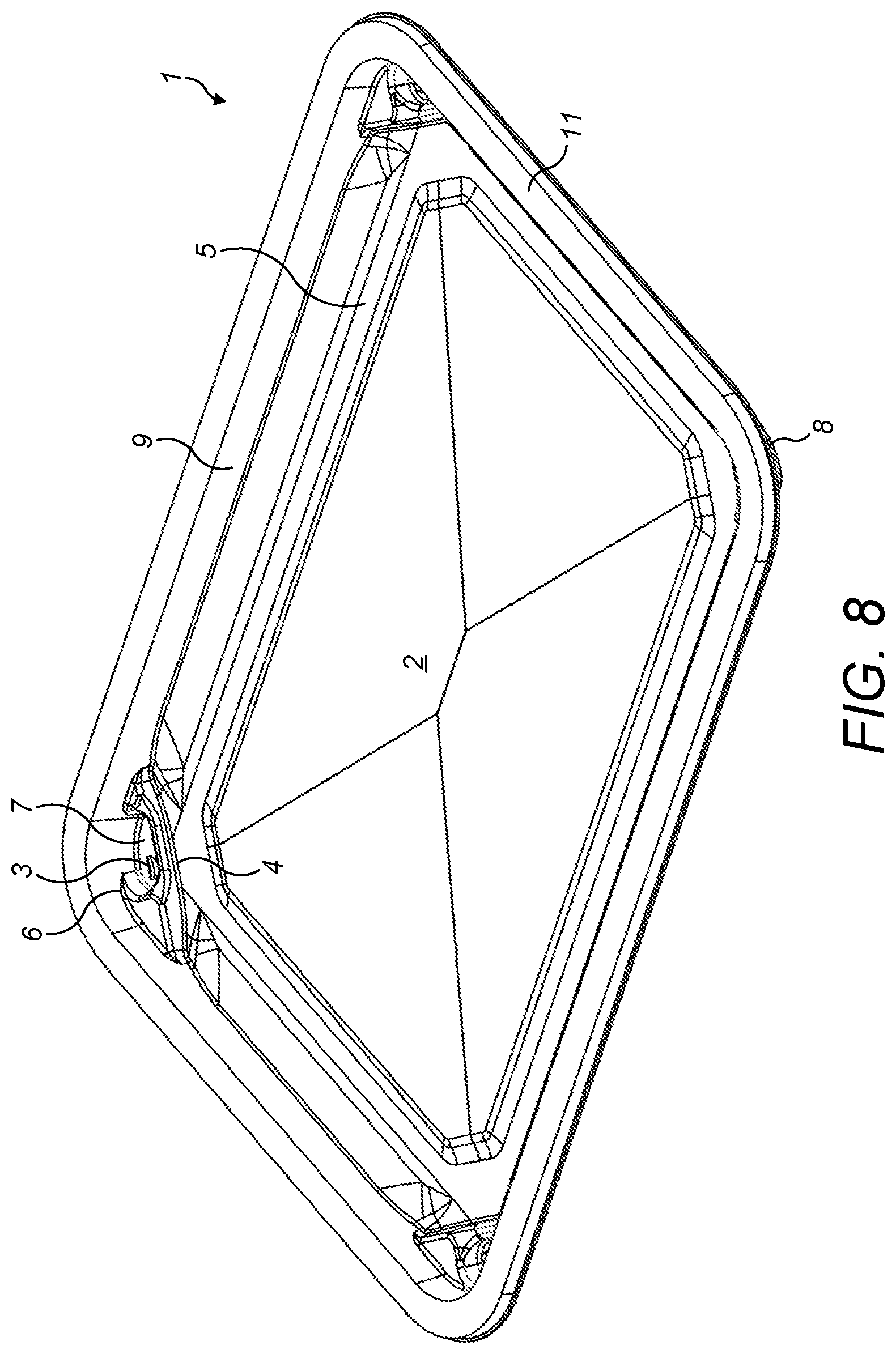
[0064] FIG. 8 is a schematic representation (perspective view) of the container of FIG. 1;
[0065] FIGS. 9A and 9B are schematic representations (side views) of the container of FIG. 1;
[0066] FIGS. 10A, 10B and 10C are partial (cross sectional) schematic representations of a container according to the present invention;
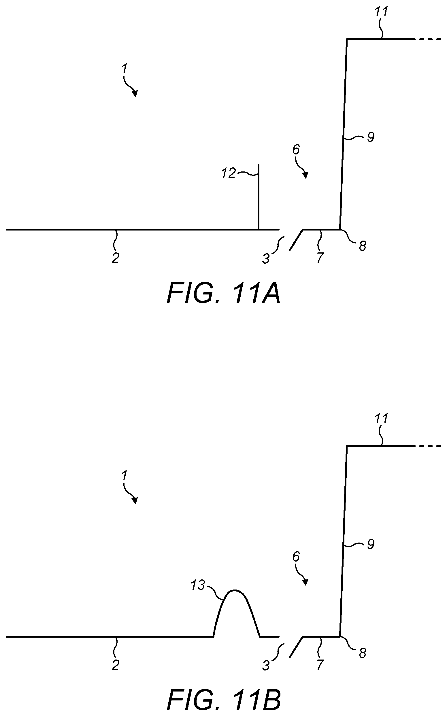
[0067] FIGS. 11A and 11B are partial (cross sectional) schematic representations of separation walls formed in a container according to the present invention;
[0068] FIG. 12 is a partial schematic representation of a separation wall according to the present invention;
[0069] FIGS. 13a to 13e are schematic representations of denesting elements used in a container according to the present invention;
[0070] FIGS. 14a and 14b illustrate the positioning of the air evacuation passage in a container according to the present invention;
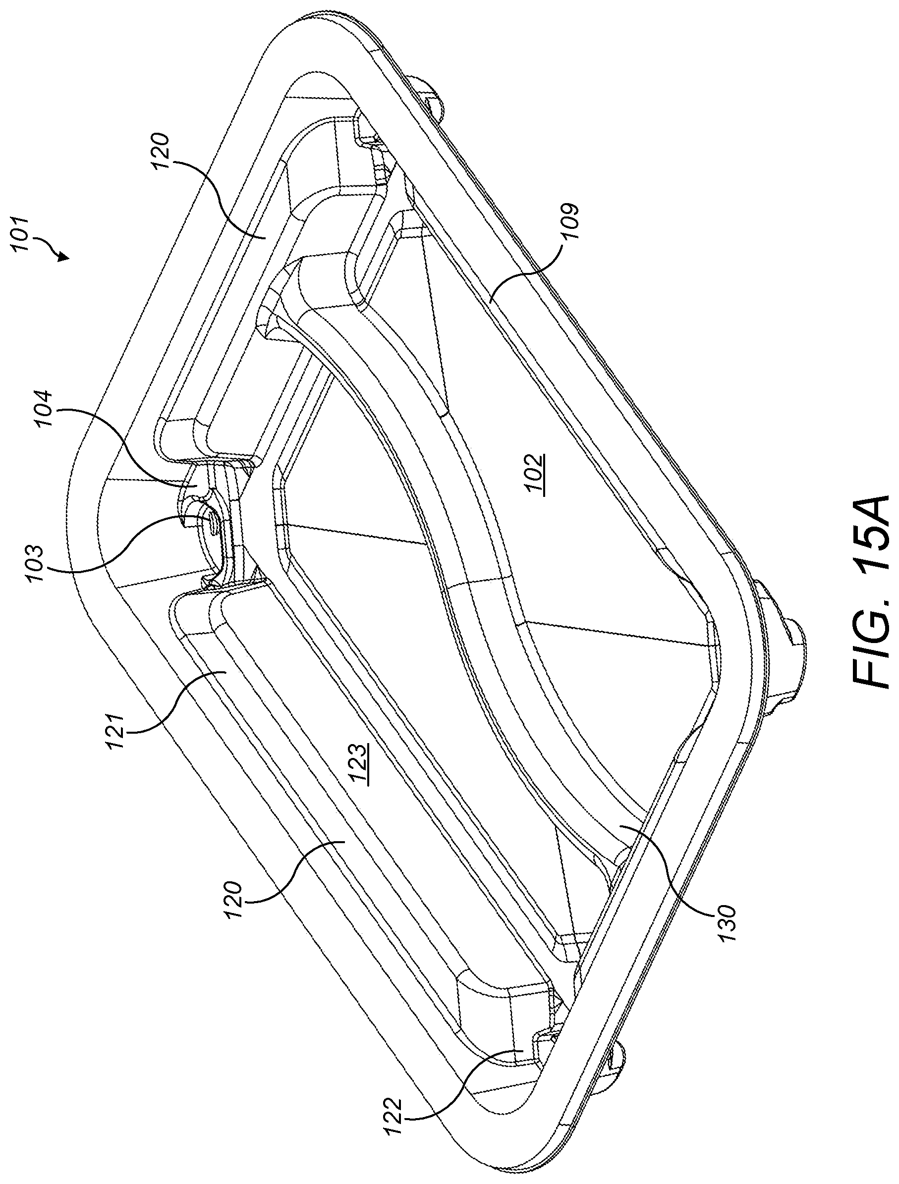
[0071] FIG. 15A is a schematic representation (perspective views) of a second container according to the present invention;
[0072] FIG. 15B is a schematic representation (perspective views) of a third container according to the present invention;
[0073] FIG. 16 is a schematic representation (perspective views) of a fourth container according to the present invention;
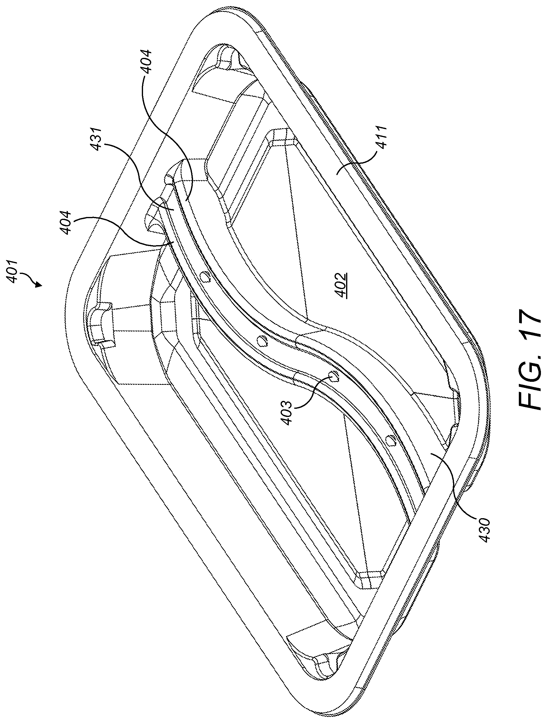
[0074] FIG. 17 is a schematic representation (perspective views) of a fifth container according to the present invention;
[0075] FIG. 18 is a schematic representation (perspective views) of a sixth container according to the present invention; and
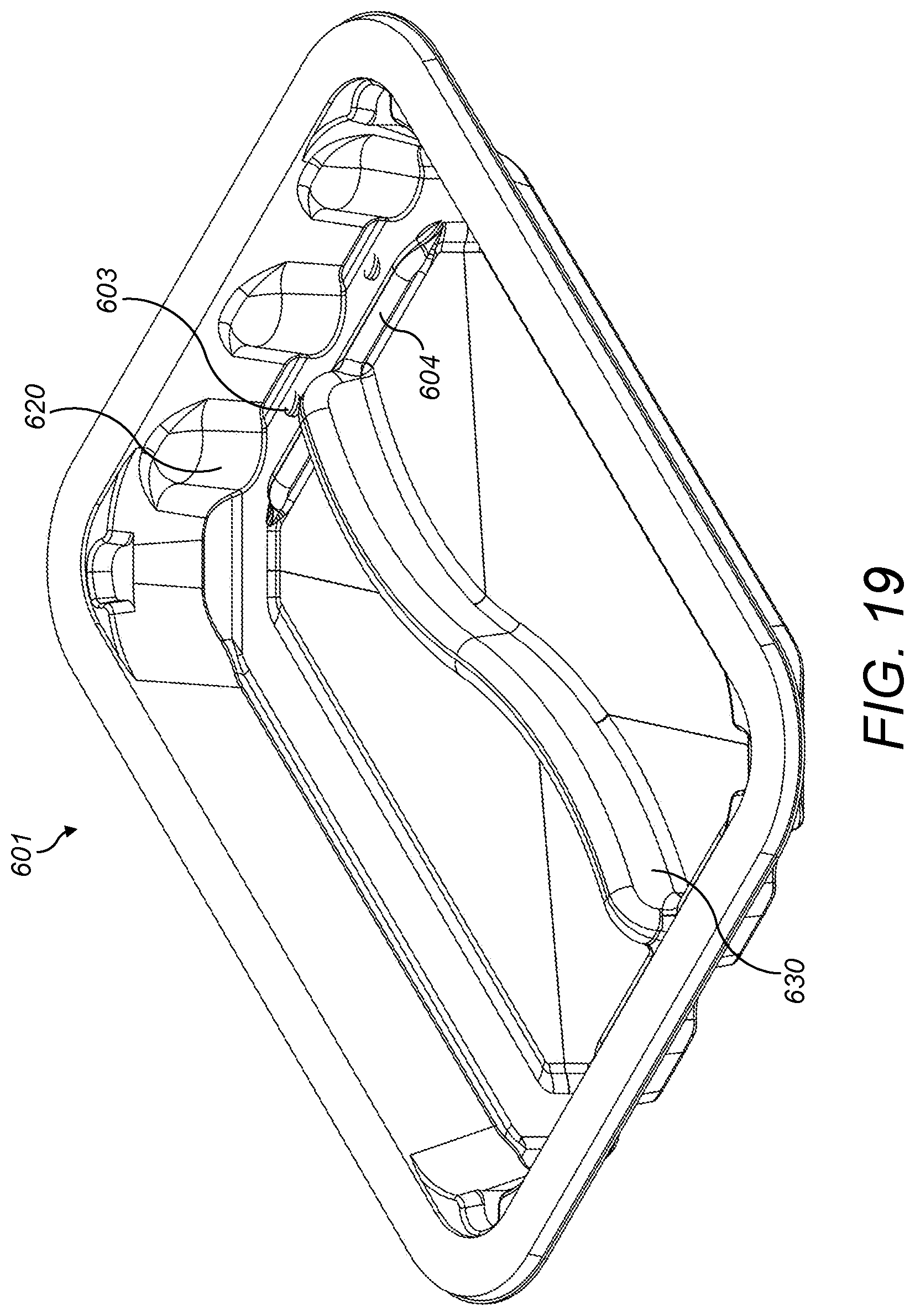
[0076] FIG. 19 is a schematic representation (perspective views) of a seventh container according to the present invention.
[0077] Referring to FIG. 1, there is illustrated a container 1 for vacuum skin packaging a product, comprising a surface 2 for supporting said product and one or more vacuum vents 3, wherein the one or more vacuum vents 3 are separated from the supporting surface 2 by one or more separation walls 4.
[0078] The container 1 comprises a peripheral flange 11 surrounding the mouth of the container 1. In use, including during packaging and displaying the product, the container 1 is positioned with the peripheral flange 11 being the uppermost structure. In other words, the mouth of the container 1 is upwards and the supporting surface 2 and/or the base of the container 1 is down. In this embodiment, the cross section of the container 1 is substantially rectangular and comprises corners 8, but other shapes of container are envisaged, such as circular, squares, triangle or less conventional shapes to fit specific product shapes. The container 1 further comprises a plurality of walls 5, including side walls 9 extending from the supporting surface 2 and/or the base 7 of the well 6.
[0079] In the present embodiment, each corner 8 of the container 1 comprises a vacuum vent 3. Each vacuum vent 3 is separated from the supporting surface 2 by a separation wall 4. The separation wall 4 acts a dam and is a barrier between the vacuum vents 3 and the supporting surface 2 and the product (not shown). Thus, the separation wall 4 protects the vacuum vents 3 and prevents contamination of the vacuum vent 3 from any juices seeping from the product.
[0080] With reference to FIG. 10A, the vacuum vents 3 are located in a plane extending from the supporting surface 2. However, in other embodiments (see FIGS. 10B and 10C), the vacuum vents 3 are located in a plane different from the plane extending from the supporting surface 2. For example, the vacuum vents 3 can be located in a plane above (in use) the plane extending from the supporting surface 2. Alternatively and/or additionally, the vacuum vents 3 can be located in a plane below (in use) the plane extending from the supporting surface 2. The dimensions, for example, the height, of the separation wall 4 can be altered accordingly.
[0081] The separation wall 4 extends from the supporting surface 2 and is integrally formed with the container 1. Preferably, the separation wall extends from the supporting surface 2 in the shape of a double-walled rib. In this embodiment, the vacuum vents 3 are located at the corners of the container 1. One vacuum vent 3 is located within a compartment, for example the well 6 of the container 1. The well 6 is formed of a base 7 (in which the vacuum vent is formed), the separating wall 4 and part of the side wall 9 of the container 1. However, the well 6 could equally be formed of a separation wall 4 surrounding the vacuum vent 3, separate from the side wall 9 of the container. The well 6 acts as a protective barrier between the vacuum vent 3 and the supporting surface 2 and the product.
[0082] Referring to FIG. 11A, the separation wall 4 can be a single partitioning wall. In this embodiment the separation wall 4 comprises a single rib 12 extending from the container 1, and the rib 12 partially surrounds the base 7 of the well 6. In another embodiment, the separation wall 4 comprises a double-walled rib 13 (FIG. 11B). The double-walled rib 13 can extend partially or fully around the perimeter of the well 6. Additionally and/or alternatively, the double-walled rib 13 follows the contour of the side wall 9 and/or the corner 8 of the container 1 so as to provide additional support and rigidity during the packing process, and subsequently during handling, transport, storage, display and use of the container 1. This specific shape also strengthens the structure of the well 6 during the sealing process, in particular during the vacuum step. This is because during the vacuum step, the container 1 is mostly supported from under the supporting surface 2. The base 7 of the well 6 is unsupported or partially supported so as to leave the vacuum vents 3 unhindered. Therefore, when vacuum is applied, the corners 8 of the container 1 comprising the separation wall(s) 4 can withstand a fair degree of pressure.
[0083] Referring to FIG. 12, the specific profile of the upper (in use) edge 14 of the separation wall 4 creates an air evacuation passage 4a. In this embodiment, the specific profile of the upper (in use) edge 14 of the separation wall 4 creates a recessed area 4b, or a channel or a dip through which air can form an accelerated stream during the air evacuation process. The accelerated air flow holds the film in a raised position in order to keep the film elevated and away from the vacuum vent(s) 3 until the final moments of the air evacuation process. The air evacuation passage 4a, or channel or dip can be formed within the separation wall 4. Preferably, a dip in the separation wall 4, together with the film at or above the uppermost (in use) edge 14 of the separation wall 4, can form the air evacuation passage 4a.
[0084] The velocity of air in the region of the air evacuation passage 4a is higher than in other inner regions of the container 1 and therefore the film is prevented from collapsing and sealing off the air evacuation passage 4. The higher velocity air also chills the film immediately above the air evacuation passage 4a, making the film less plastic (i.e. the film is less malleable or flexible) preventing premature sealing of the film to the separation wall 4 and/or the vacuum vents 3.
[0085] The air evacuation passage 4a causes the air stream to accelerate in the direction of the vacuum vents 3, facilitating the efficient evacuation of air from the container 1. The accelerated air stream formed by the evacuation passage 4a prevents the film from closing until all of the air within the container 1 has been evacuated. Additionally, the air evacuation passage 4a causes the velocity of air flowing from the inner region of the container 1 to accelerate prior to evacuation of the air via the vacuum vents 3. This is particularly advantageous at the end of the vacuum sealing step, where the majority of the air has been evacuated. The air flow is accelerated so as to quickly and efficiently remove the final remnants of air.
[0086] The base 7 of the well 6 is shaped so as to follow the contour of the container 1 and of the inner contours of the separating wall 4. A vacuum vent 3 is located in the base of the well 6. In the present embodiment, the vent 3 is offset from the centre of the base 7 of the well 6. However, it can be positioned centrally or it can form the whole base 7 of the well 6.
[0087] With reference to FIG. 4, the separation wall 4 comprises a middle portion 15a, in which the air evacuation passage 4a is formed. The upper edge of the separation wall 4 extends, substantially parallel to the supporting surface 2, to the side wall 9 of the container, so as to define the mouth of the well 6. In this embodiment, the mouth of the well 6 is asymmetrical so that the extension comprises one larger 15b side portion and one smaller side portion 15b, on either side of the mouth of the well 6.
[0088] As mentioned above, the well 6 and the separation wall 4 also serve as a denesting feature to prevent nested containers from being stuck to each other. Preferably, the denest feature is a AB-type denesting feature, in which the denest element of a first top container is different from the denest element from a second bottom container. The containers according to the present invention comprise denest elements such that the denest element of a first bottom container in a pile of nested container, is formed at a 45.degree. angle relative to the corresponding denest element of a second top container nested in said first container. In a preferred embodiment, the denest element of a first bottom container in a pile of nested container, is formed as a mirror image of the corresponding denest element of a second top container nested in said first container. In a most preferred embodiment, the denest element of a first bottom container in a pile of nested container, is formed at a 45.degree. angle relative to the corresponding denest element of a second top container nested in said first container and is formed as a mirror image to said second denest element, as illustrated in FIGS. 1 and 13a to 13e.
[0089] The air evacuation passage 4a is formed in the separation wall 4 so as to be aligned with the well 6 as illustrated in FIGS. 14a and 14 b and to enable efficient air flow from the containing space of the container 1 to the well 6, through the vacuum vent 3. Preferably, the middle portion 15a of a first bottom denest element is formed as a mirror image of the corresponding middle portion 15a of a second top container nested in said first container (also shown in FIGS. 14a and 14b).
[0090] Whether the separation wall 4 is single-walled or formed with a plurality of walls it is preferred that it is integrally formed for robustness, to prevent deformation during the vacuum step and so that the manufacturing process is simpler and less costly.
[0091] The vacuum vents 3 comprise a hinged flap 10. The hinged flap 10 is produced by punching or perforation of the container 1. The cross-section of the hinged flap 10 in a horizontal plane perpendicular to the container 1 (in use) is a semicircle, whereby the straight, non-perforated/non-punched edge of the semicircle forms the hinge. However, other shapes of hinged flap are envisaged, including square and rectangular. Each hinged flap 10 of the vacuum vent 3 is formed in the base 7 of the well 6. Accordingly, the vacuum vent 3 and hinged flap 10 are positioned at the lowermost location of the well 6 of the container 1 (in use). Each vacuum vent 3 is formed in the base 7 of a well 6. In this embodiment, the area of vacuum vent 3 and thus the hinged flap 10 is smaller than the area of base 7 of the well 6. Therefore, the vacuum vent 3 and the hinged flap 10 do not cover the entirety of the base 7.
[0092] The container 1 according to the present invention can be produced by thermoforming. The container 1 comprises a monolayer or multilayer sheet of material(s), said material(s) being selected from virgin or recycled polymeric material(s) such as virgin or recycled polyethylene terephthalate (PET), polypropylene (PP), carton board and pulp, aluminium, or plant-based plastic alternatives.
[0093] In use, the container 1 is formed by thermo-forming a sheet of plastics material(s). The container 1 comprises a monolayer or multilayer sheet of material(s), said material(s) being selected from virgin or recycled polymeric material(s) such as such as virgin or recycled polyethylene terephthalate (PET), polypropylene (PP), carton board and pulp, aluminium, or plant-based plastic alternatives. A product is placed on the supporting surface 2 of the container 1 and the supported product is placed in a vacuum chamber.
[0094] A film (not shown) is positioned above the supported product and the container 1, for example by being drawn upwards by applying a vacuum, to form a dome shape above the container 1. The film is heated at temperatures ranging from 160.degree. C. to 240.degree. C., which are high enough so that the film material softens. The film is then sucked downwards towards the product and the support, preferably by application of vacuum.
[0095] The film contacts and adheres to the structures of the container 1 and the product in a sequential order starting from the uppermost structures (in use). For example, the film contacts the flange 11 of the container 1, then the top of the contained product, then the side walls 9, then the supporting surface and the protective separation wall(s) 4 so that the last structure to be the film adheres to is the vacuum vents 3. The sealing sequence is therefore as follows: [0096] 1. The film contacts and adheres to the flange 11 or edges of the container 1. This is of particular significance for deep containers where (a) there is a larger volume of air to be evacuated and (b) the film has an increased distance to travel. [0097] 2. The film contacts and adheres to the top of the contained product between the flange 11 and the supporting surface 2. [0098] 3. The film contacts the side walls 9 of the container 1 (gradually from top to bottom). In the prior art containers comprising apertures in close proximity to the flange, it will be at this point in the air evacuation process that the apertures are contacted by the film and closed off. Accordingly, the apertures can no longer evacuate air after closure by the film. Thus, there is still a risk that air pockets will remain and consequently that the shelf-life of the product will be reduced. [0099] 4. The film contacts to the supporting surface 2. [0100] 5. The film contacts and adheres to the protective separation wall 4. [0101] 6. Lastly, the film contacts and adheres to the one or more vacuum vents 3.
[0102] Therefore, the one or more vacuum vents 3 are the final structure(s) to be contacted and adhered to by the film due to the presence of the surrounding separation wall 4. Accordingly, the vacuum vents 3 are the final structure around which air is evacuated, it is therefore possible to accelerate the sealing process without compromising on the quality and homogeneity of the sealing, thus providing for a fast, efficient and forgiving sealing step.
[0103] Owing to the structure of the container 1 according to the present invention, the sealing step, and therefore the vacuum skin packaging process as a whole, can be carried out at high speed without compromising the quality of the seal. However fast the sealing step is carried out, the film will sequentially adhere to the surfaces of the container 1 and seal the vacuum vents 3 last. The product can be packaged without any unsightly air pockets, without decreasing the shelf-life, and without contamination from juices seeping from the product during the vacuum step.
[0104] FIGS. 15 to 19 illustrate further embodiments of containers according to the present invention, wherein vacuum vents are provided which are separated from the supporting surface by one or more separation walls. A detailed description of features which may be included in the containers according to the present invention are described above and the following paragraphs provide information on additional or alternative features of containers according to the present invention.
[0105] FIG. 15A shows a container 101 for vacuum skin packaging a product comprising a surface 102 for supporting said product and one or more vacuum vents 103, wherein the one or more vacuum vents are separated from the supporting surface by one or more separation walls 104. The container 101 may further comprise ribs or shelves 120 extending from one or more side walls 109. The ribs or shelves 120 prevent the product and/or its juices from blocking the vacuum vents 103. In this embodiment, elongated shelves 120 extend from each of the four side walls 109. Each shelf 120 comprises a platform 121, side walls 122 and a front wall 123 extending from the edges of said platform. The side walls 122 may extend perpendicularly or non-perpendicularly from the platform 121 edges. The edges of each shelf 120 are rounded so as to avoid damage to the product. The shelf 120 preferably extend along a side wall 109 of the container 101, from one separation wall 104 in a corner of the container 120 to the separation wall 104 in the next corner of the container 120.
[0106] The container of the present invention may also comprise one or more divider walls 130 for dividing the supporting surface into two or more compartments. In a preferred embodiment, the container comprises one substantially S-shaped divider wall dividing the container into two compartments. In these embodiments, each compartment is in gas communication with one or more vacuum vents so as to allow the vacuum skin packaging of the products placed in each compartments. The dividing wall extends from one side wall of the container to the opposite side wall, or from one shelf to the opposite shelf depending on the configuration. The height of the divider wall may be such that it levels with the peripheral flange. However in the context of the present invention, it is preferred that the top of the divider wall is lower than the plane of the peripheral flange so as to allow the products in each compartments to be individually vacuum skin packaged.
[0107] FIG. 15B shows a variation of the container 101 of FIG. 15A, a container 201 for vacuum skin packaging a product comprising a surface 202 for supporting said product and one or more vacuum vents 203, wherein the one or more vacuum vents are separated from the supporting surface by one or more separation walls 204. The container 201 may comprise a divider wall 230 to divide the container 201 into two compartments. Instead of a rib or shelf 120 extending along the side wall 109, the container 201 comprises two ribs or protrusions 220 extending from the side wall 209, i.e. one on each side of the separation wall 204. Preferably, the two protrusions 220 are separate and leave a gap therebetween so as to allow the passage of gas, but to prevent hindering of the vacuum vents 203 by the product.
[0108] FIG. 16 shows a container 301 for vacuum skin packaging a product comprising a surface 202 for supporting said product and one or more vacuum vents 303, wherein the one or more vacuum vents are separated from the supporting surface by one or more separation walls 304. This container 301 differs from the preceding embodiments in that the vacuum vents 303 are positioned outside the side walls 309 of the container 301. In this embodiment, the container 301 comprises a first peripheral flange 311 extending around the mouth of the container 301 and a second peripheral flange 340 extending outwardly from the side walls 309 of the container 301. The height of the second peripheral flange 340 on the side wall 309 is such that the vacuum vents 304 formed therein are substantially in the plane extending from the supporting surface 302. A compartment or well 306 is positioned, for example at each corner of the container 301, and a vacuum vent 304 can be formed, punched or perforated in each compartment or well 6 (preferably, in the base thereof).
[0109] FIG. 17 shows a container 401 for vacuum skin packaging a product comprising a surface 402 for supporting said product and one or more vacuum vents 403, wherein the one or more vacuum vents are separated from the supporting surface by one or more separation walls 404. This container 401 differs from the preceding embodiments in that the vacuum vents 403 are positioned on the divider wall 430. More particularly, the container 401 comprises a recess 431 extending substantially along the upper surface of the divider wall 430. The recess 431 is separated from the supporting surface of the container 401 by one or more separation walls 404, formed on either side of the recess 431 so as to partially or completely surround the recess 431. The vacuum vents 403 are formed along said recess 431. In this embodiment, it is preferred that the upper surface of the divider wall 430 is below the plane of the peripheral flange 411 surrounding the mouth of the container 401 so as to allow efficient evacuation of the atmosphere within the container 401.
[0110] FIG. 18 shows a container 501 for vacuum skin packaging a product comprising a surface 502 for supporting said product and one or more vacuum vents 503, wherein the one or more vacuum vents are separated from the supporting surface by one or more separation walls 504. This container 501 differs from the preceding embodiments in that the vacuum vents 503 are formed on columns 540 extending from the supporting surface 502. Preferably, the container 501 comprises one or more columns 540 extending from its supporting surface 502. Where the supporting surface 502 is divided into two or more compartments, for example by a divider wall 530, each compartment comprises at least one column 540. In this embodiment, the column 540 is substantially cylindrical but may have alternative shapes. One or more separating walls 504 extend (in use, vertically) from the upper surface of said column 540 so as to partially or completely surround a vacuum vent 503 formed in the upper surface of said column 540. In this embodiment, it is preferred that the upper surface of the columns 530 is below the plane of the peripheral flange 511 so as to allow efficient evacuation of the atmosphere within the container 501.
[0111] FIG. 19 shows a container 601 for vacuum skin packaging a product comprising a surface 602 for supporting said product and one or more vacuum vents 603, wherein the one or more vacuum vents are separated from the supporting surface by one or more separation walls 604. The container 601 may or may comprise a divider wall 630 for dividing the container 601 into two compartments. In this embodiment, the vacuum vents 603 are formed in the plane extending from the supporting surface 602, but separated from said supporting surface by one or more separation walls 604. The container 601 may also comprise one or more ribs or protrusions 620 extending from the side wall 609 of the container 601 and adjacent each vacuum vent 603 (preferably on either side thereof) so as to prevent the product from hindering the vacuum vent 603.
[0112] Thus, from the above description, it can be seen that the present invention provides a container having advantages including minimising and/or preventing the leakage of juice from a moisture-containing product during the air evacuation step and accelerating the vacuum sealing step without compromising the homogeneity, i.e. the quality, of the seal. The container according to the present invention thus prolongs the shelf-life of the contained product.
* * * * *
D00000
D00001
D00002
D00003
D00004
D00005
D00006
D00007
D00008
D00009
D00010
D00011
D00012

D00013

D00014

D00015
D00016

D00017

D00018
D00019

D00020
XML
uspto.report is an independent third-party trademark research tool that is not affiliated, endorsed, or sponsored by the United States Patent and Trademark Office (USPTO) or any other governmental organization. The information provided by uspto.report is based on publicly available data at the time of writing and is intended for informational purposes only.
While we strive to provide accurate and up-to-date information, we do not guarantee the accuracy, completeness, reliability, or suitability of the information displayed on this site. The use of this site is at your own risk. Any reliance you place on such information is therefore strictly at your own risk.
All official trademark data, including owner information, should be verified by visiting the official USPTO website at www.uspto.gov. This site is not intended to replace professional legal advice and should not be used as a substitute for consulting with a legal professional who is knowledgeable about trademark law.