Coupleable Crate
BRUNNER; Yaron ; et al.
U.S. patent application number 16/966776 was filed with the patent office on 2021-02-11 for coupleable crate. This patent application is currently assigned to KETER PLASTIC LTD.. The applicant listed for this patent is KETER PLASTIC LTD., MILWAUKEE ELECTRIC TOOL CORPORATION. Invention is credited to Yaron BRUNNER, Omer MENASHRI, Grant T. SQUIERS.
| Application Number | 20210039831 16/966776 |
| Document ID | / |
| Family ID | 1000005211218 |
| Filed Date | 2021-02-11 |


View All Diagrams
| United States Patent Application | 20210039831 |
| Kind Code | A1 |
| BRUNNER; Yaron ; et al. | February 11, 2021 |
COUPLEABLE CRATE
Abstract
Provided is a crate coupleable to another crate or to a variety of carrying platforms.
| Inventors: | BRUNNER; Yaron; (Kibbutz Gvat, IL) ; MENASHRI; Omer; (Kibbutz Afikim, IL) ; SQUIERS; Grant T.; (Cudahy, WI) | ||||||||||
| Applicant: |
|
||||||||||
|---|---|---|---|---|---|---|---|---|---|---|---|
| Assignee: | KETER PLASTIC LTD. Herzliya WI MILWAUKEE ELECTRIC TOOL CORPORATION Brookfield |
||||||||||
| Family ID: | 1000005211218 | ||||||||||
| Appl. No.: | 16/966776 | ||||||||||
| Filed: | January 31, 2019 | ||||||||||
| PCT Filed: | January 31, 2019 | ||||||||||
| PCT NO: | PCT/IL2019/050124 | ||||||||||
| 371 Date: | July 31, 2020 |
| Current U.S. Class: | 1/1 |
| Current CPC Class: | B65D 25/20 20130101; B65D 25/2885 20130101; B65D 21/0212 20130101 |
| International Class: | B65D 21/02 20060101 B65D021/02; B65D 25/28 20060101 B65D025/28; B65D 25/20 20060101 B65D025/20 |
Foreign Application Data
| Date | Code | Application Number |
|---|---|---|
| Feb 1, 2018 | IL | 257294 |
Claims
1.-31. (canceled)
32. A crate having a base and side-walls upwardly extending from the base, of which at least two opposite side-walls are locking side-walls extending parallel to one another, each of the locking side-walls is configured at a top or a bottom surface thereof with at least one sliding locking slot extending parallel to said locking side-wall and defining a primary sliding path; said at least one sliding locking slot is configured with at least one arresting rib; another one of the top or a bottom surface of the locking side-walls is configured with at least one locking tongue disposed parallel to said locking side-wall and configured for sliding arresting with a respective locking slot, and a third wall, extending between the two parallel locking side-walls, is configured at one of a top end and a bottom end with a locking latch, slidingly displaceable, normal to said primary sliding path, between a retracted position and a projecting position, wherein at the projecting position it is configured for engaging a latch arresting portion of another one of a top end and a bottom end of a third wall edge of a top or bottom crate, respectively.
33. The crate of claim 32, wherein the sliding locking slots constitute sliding female coupling members of one object, and the locking tongues constitute male coupling members of a male-female coupling system of another object, wherein the male coupling member is configured for engaging a female coupling member such that sliding the male coupling member into the female coupling member along a sliding path causes the male coupling member to be arrested by the female coupling member, thus causing coupling between the one object and the other object.
34. The crate of claim 32, wherein at a stacked position, where the crate is mounted over a second, like crate, the locking latch is engageable with the latch arresting portion thereby preventing sliding displacing the crate along the primary sliding path, as a consequence of which the crate cannot detach from the second crate.
35. The crate of claim 34, wherein at the stacked position, the base edges of a top crate configured with locking tongue male projections, engage with female type locking slots configured at the top edges of the bottom crate, slidably engageable along said primary sliding path and arrested in a vertical direction, wherein the locking latch prevents sliding displacement of the crates, so that the stacked crates are securely stacked and engaged with one another.
36. The crate of claim 32, comprising one or more features selected from the group consisting of: (i) the crate is rectangular, with the two locking side-walls being left and right side-walls of the crate, and the third wall being a front or a rear side-wall of the crate, (ii) at least the locking side-walls of the crate extend to the same height from the base of the crate, (iii) the third wall is shorter than the two locking side walls, and wherein a base portion of the crate, below the third wall is configured with a downwardly extending portion for concealing a gap between stacked crates, at the event of a shorter third wall, and (iv) the at least one arresting rib of the sliding locking slots extends flush with a top or bottom surface, respectively, of a locking side-wall.
37. The crate of claim 32, wherein (i) the locking tongues are disposed below or substantially flush with a bottom surface of the crate, and/or (ii) the locking latch is normally biased into its projecting position.
38. The crate of claim 32, wherein the locking latch has at least one feature selected from (i) being manually displaceable between its respective projecting position and retracted position, and (ii) being received within a latch space extending between a double walled cavity, with an opening formed at an external wall surface of the latch space for accessing a latch manipulating portion of said locking latch, for manipulating the latch into its retracted position.
39. The crate of claim 32, wherein the locking latch extends from a bottom end of the third wall and is configured for engaging with a latch arresting portion at a top of a third wall of a second crate below said crate.
40. The crate of claim 39, wherein the latch arresting portion is an inside wall surface of the third wall of a crate below said crate.
41. The crate of claim 32, wherein the locking latch and the latch arresting portion are configured at a front wall of the crate, where the primary sliding path extends between the front wall to a rear wall of the crate.
42. The crate of claim 32, wherein a gliding ramp portion is configured at the third wall, for guidance of the locking latch into latch arresting portion.
43. The crate of claim 32, wherein carrying handles are configured at an outside wall surface of at least at two opposite side walls.
44. The crate of claim 32, wherein the third wall of the crate is configured with a manipulating handle.
45. The crate of claim 44, wherein (i) the manipulating handle is disposed within finger reach from the locking latch manipulating portion, or (ii) the locking latch is manipulable between the projecting position and the retracted position using a single finger of a hand, whilst simultaneously holding the manipulating handle.
46. The crate of claim 32, wherein the locking latch normally projecting from a bottom face of the crate, whereby one or more protecting seat members are provided, extending at least at the vicinity of the locking latch to an extent substantially similar to a projecting length of the locking latch.
47. The crate of claim 32, wherein a top surface of the locking side-walls is configured with one or more protuberances configured with a substantially upright outside-facing surface and an inclined inside-facing surface; the protuberances are configured for engaging within depressions disposed in register at a bottom surface of a like-crate stacked above, to thereby prevent outwards buckling of the locking side walls of a bottom crate.
48. The crate of claim 32, further configured with an auxiliary coupling arrangement for sliding articulating the crate to another object, wherein the auxiliary coupling arrangement is configured on an outside face of one or more of any of the side walls of the crate and on the base of the crate.
49. The crate of claim 48, wherein (i) the object is a mounting platform articulated to any stationary or mobile member, disposed vertically or horizontally, and configured with one or more female couplers elements of a male-female coupling, or (ii) the auxiliary coupling arrangement comprises one or more male-female slider coupler type elements on an outside face the base of the crate.
50. The crate of claim 48, wherein the auxiliary coupling arrangement comprises one or more male-female slider coupler type elements on an outside face of one or more of the side walls of the crate.
51. The crate of claim 50, wherein (i) the auxiliary sliding path extends parallel to, or normal to a primary sliding path of the crate, (ii) the one or more auxiliary male coupling member is configured for engaging a female coupling member such that sliding the auxiliary male coupling member into the female coupling member along a sliding path causes the male coupling member to be arrested by the female coupling member, thus causing coupling between the crate and the objects, or (iii) wherein the auxiliary coupling arrangement is configured with one or more support female coupling elements, in addition to the auxiliary male coupling member, extending along the auxiliary sliding path, for sliding engaging with respective one or more support male coupling elements projecting from the other object, thereby reinforcing articulation of the crate to the other object.
52. The crate of claim 32, comprising one or more auxiliary male coupling members for sliding coupling engagement with a female coupling member of a male-female slider coupler, the auxiliary male coupling member having a female-engaging portion projecting from an outside face of the crate and comprising at least one locking tongue projecting laterally outwardly from the female-engaging portion, the auxiliary male coupling member being configured for sliding engagement with one or more inwardly-directed arresting ribs of a female coupling member of the object, wherein coupling engagement takes place along an auxiliary sliding path.
53. The crate of claim 52, wherein the female coupling member comprising a depressed locking location defined in a surface of a second object, said depressed locking location defined by surface boundaries, said depressed locking location defining said auxiliary sliding path extending between a male coupling member insertion end and a male coupling member arresting end, and configured with at least one arresting rib laterally inwardly extending from the surface boundaries, the female coupling member being configured for slidingly receiving a male coupling member along the auxiliary sliding path.
Description
TECHNOLOGICAL FIELD
[0001] The present disclosure is concerned with a crate coupleable to another crate or to a variety of carrying platforms.
BACKGROUND ART
[0002] References considered to be relevant as background to the presently disclosed subject matter are listed below: [0003] DE102015112204 [0004] WO2017191628 [0005] EP2346741
[0006] Acknowledgement of the above references herein is not to be inferred as meaning that these are in any way relevant to the patentability of the presently disclosed subject matter.
BACKGROUND
[0007] EP2346741 discloses a storage arrangement comprising two or more cases or a case and a lid, all parts that can be stacked and interconnected and where the cases or lids have opposite facing gables and where a connecting bridge is placed in the four corners or with one connecting bridge on each of the opposite facing gables, wherein each connecting bridge is provided with a top bridge on top and with a bottom bridge on the bottom, whereby in the interconnected state of the parts the bottom bridge of the upper case or lid interconnects with the top bridge of the below case or lid, wherein the bottom bridge of the top case or lid is shaped as a male part having a downward pointing L profile which interconnects with the top bridge of the below case which is shaped as a female part also having an L profile, characterized in, that the L profiles of the top bridges and of the bottom bridges have the same lateral orientation such that when the bottom bridges of the top case or lid are placed above the opposite top bridges of the lower case or lid they will get in gear and with a sidewards push on the top case or lid be brought into a tight and compact condition, and that a transport lock is provided on the case or lid for blocking disassembly and keeping the top bridges and bottom bridges in tight and compact coupling, such transport lock being able to be activated outside the case or lid by a locking knob.
[0008] DE102015112204 discloses a stackable container for forming a container stack along a vertical stacking axis comprising a plurality of stackable containers with a body having at least one container bottom and a container cover, wherein the body belongs to forming a connecting device on the bottom side connecting elements which are designed to cooperate with counter-connecting elements in the region of the container ceiling of a second stackable container and the container has a locking device with respect to the body movably mounted locking element for cooperation with an anti-locking element of the second stackable container, characterized in that in each case the connecting elements and the mating connecting elements immovable with respect to the body are formed and the connecting device alone is formed at least for the positive reception of vertical tensile forces.
[0009] WO2017191628 discloses a coupling mechanism configured for readily detachably attaching a first utility module to a second utility module, the coupling mechanism comprising a male coupler at a face of one of the first utility module and the second utility module, and a female coupler at a face of the other one of the first utility module and the second utility module, said female coupler having a depressed locking location configured with at least one locking rib extending above a depressed surface and along a sliding path, and having an open edge facing in a first sense; said male coupler having a projecting locking location disposed in register with said depressed locking location and configured with at least one locking tongue extending along said engaging sliding path at a second sense, opposite to said first sense, and configured for arresting engagement at a space between said locking rib and depressed surface, the coupling mechanism further comprises at least one locking member for arresting the first utility module with respect to said second utility module and preventing sliding displacement along said sliding path.
GENERAL DESCRIPTION
[0010] According to the present disclosure, there is provided a crate configured with coupling members rendering it coupleable to other crates or to different types of articulable platforms.
[0011] According to an aspect of the disclosure, provided is a crate that has a base and side-walls upwardly extending from the base, of which at least two opposite side-walls are locking side-walls extending parallel to one another. Each of the locking side-walls is configured at a top or a bottom surface thereof with at least one sliding locking slot extending parallel to said locking side-wall and defining a primary sliding path. The at least one sliding locking slot is configured with at least one arresting rib. Another one of the top or a bottom surface of the locking side-walls is configured with at least one locking tongue disposed parallel to said locking side-wall and configured for sliding arresting with a respective locking slot, and a third wall, extending between the two parallel locking side-walls, is configured at one of a top end and a bottom end with a locking latch. The locking latch is slidingly displaceable, normal to said primary sliding path, between a retracted position and a projecting position, wherein at the projecting position it is configured for engaging a latch arresting portion of another one of a top end and a bottom end of a third wall edge of a top or bottom crate, respectively.
[0012] The disclosure is such that the sliding locking slots constitute sliding female coupling members, and the locking tongues constitute male coupling members of a male-female coupling system, wherein the one or more male coupling member is configured for engaging a female coupling member, such that sliding the male coupling member into the female coupling member along a sliding path causes the male coupling member to be arrested by the female coupling member, thus causing coupling therebetween.
[0013] At a stacked position, where the crate is mounted over a second, like crate, the locking latch is engageable with the latch arresting portion, thereby preventing sliding displacing the crate along the primary sliding path, as a consequence of which the crate cannot detach from the second crate.
[0014] At the stacked position, the base edges of a top crate configured with locking tongue male projections, engage with the female type locking slots configured at the top edges of the bottom crate, slidably engageable along said primary sliding path and arrested in a vertical sense, i.e. prevented from separating from one another, wherein the locking latch prevents sliding displacement of the crates, so that the stacked crates are securely stacked and engaged with one another.
[0015] The crate can further be configured with an auxiliary coupling arrangement for sliding articulating the crate to another object (crate or any other object). The auxiliary coupling arrangement can be configured on an outside face of one or more of any of the side-walls of the crate and on the base of the crate.
[0016] According to one example of the disclosure, the auxiliary coupling arrangement comprises one or more male-female slider coupler type elements on one or more of side-walls of the crate.
[0017] According to another example of the disclosure, the auxiliary coupling arrangement comprises one or more male-female slider coupler type elements on an outside face the base.
[0018] A crate according to the disclosure can be configured with an auxiliary coupling arrangement on one or more side-walls and on the base.
[0019] According to specific examples of the disclosure, the crate is configured with one or more auxiliary male coupling members for sliding coupling engagement with a female coupling member of a male-female slider coupler, the auxiliary male coupling member having a female-engaging portion projecting from an outside face of the crate and comprising at least one locking tongue projecting laterally outwardly from the female-engaging portion, the auxiliary male coupling member being configured for sliding engagement with one or more inwardly-directed arresting ribs of a female coupling member of the object, wherein coupling engagement takes place along an auxiliary sliding path.
[0020] The auxiliary sliding path can extend parallel to or normal to the primary sliding path of the crate.
[0021] The one or more auxiliary male coupling member is configured for engaging a female coupling member, such that sliding the auxiliary male coupling member into the female coupling member along a sliding path causes the male coupling member to be arrested by the female coupling member, thus causing coupling between first and second objects (e.g. a couple of crates or a crate to another object).
[0022] The second object can be a mounting platform articulated to any stationary or mobile member, e.g. a wall, floor, ceiling of a structure or a vehicle, hand truck and the like, disposed vertically or horizontally, and configured with one or more female couplers elements of a male-female coupling.
[0023] The female coupling member comprising a depressed locking location defined in a surface of a second object, said depressed locking location defined by surface boundaries, said depressed locking location defining said auxiliary sliding path extending between a male coupling member insertion end and a male coupling member arresting end, and configured with at least one arresting rib laterally inwardly extending from the surface boundaries, the female coupling member being configured for slidingly receiving a male coupling member along the auxiliary sliding path.
[0024] The coupling being such that once engagement between the male and female coupling members takes place (namely when the one or more locking tongues and the corresponding one or more respective arresting ribs are engaged), vertical separation between the first and second objects is prevented (i.e. preventing lifting of the first from the second object).
[0025] Any one or more of the following features designs and configurations can be incorporated in a crate according to any of the aspects of the present disclosure, independently or at various combinations thereof: [0026] The crate can be rectangular, with the two locking side-walls being left and right side-walls of the crate, and the third wall being a front or a rear side-wall of the crate; [0027] At least the locking side-walls of the crate extend to the same height from the base of the crate; [0028] The third wall can be shorter than the two locking side-walls; [0029] A base portion of the crate, below the third wall, can have a downwardly extending portion for concealing a gap between stacked crates, at the event of a shorter third wall; [0030] A back wall of the crate can extend substantially the same height as the two locking side-walls; [0031] The at least one arresting rib of the sliding locking slots can extend flush with a top or bottom surface, respectively, of a locking side-wall; [0032] The locking tongues can be disposed below or substantially flush with a bottom surface of the crate; [0033] The locking latch can be normally biased into its projecting position; [0034] The locking latch can be manually displaceable between its respective retracted position and projecting position; [0035] The locking latch can be received within a latch space extending between a double walled cavity, with an opening formed at an external wall surface of said latch space for accessing a latch manipulating portion of said locking latch, for manipulating the latch into its retracted position; [0036] The locking latch can extend from a bottom end of the third wall and be configured for engaging with a latch arresting portion at a top of a third wall of a second crate below said crate; [0037] The latch arresting portion can be an inside wall surface of the third wall of the second object or second crate; [0038] A top surface of the locking side walls is configured with one or more protuberances. The protuberances can be configured with a substantially upright outside facing surface and an inclined inside facing surface; the protuberances can be configured for engaging within depressions disposed in register at a bottom surface of a like-crate stacked above, to thereby prevent outwards buckling of the locking side walls of a bottom crate; [0039] The locking latch and the latch arresting portion can be configured at a front wall of the crate, where the primary sliding path extends between the front wall to a rear wall of the crate; [0040] A gliding ramp portion is configured at the third wall, for guidance of the locking latch into latch arresting portion; [0041] The crate can be configured with carrying handles at an outside wall surface of at least at two opposite side-walls; [0042] The third face of the crate can be configured with a manipulating handle; the manipulating handle can be fixed or pivotally articulated to the crate. [0043] The manipulating handle can be disposed within finger reach from the locking latch manipulating portion; [0044] The locking latch manipulating portion can be manipulated using a single finger of a hand, whilst simultaneously holding the manipulating handle; [0045] The locking latch can be configured for normally projecting from a bottom face of the crate, whereby one or more protecting seat members are provided, extending at least at the vicinity of the locking latch to an extent substantially similar to a projecting length of the locking latch; [0046] The crate can be configured with a cover. The cover an be pivotally or slidingly secured to the crate; [0047] The cover can be configured with one or more auxiliary male-female coupling members; [0048] The auxiliary coupling arrangement can be configured with one or more support female coupling elements, in addition to the auxiliary male coupling member, extending along the auxiliary sliding path, for sliding engaging with respective one or more support male coupling elements projecting from the other object, thereby reinforcing articulation of the crate to the other object; [0049] The crate can be a container of any type, size and shape. [0050] The crate can be mounted on a mounting member with the crate opening oriented at any direction. The following are crate mounting examples: [0051] the crate can be articulated to a ceiling mounted plate, at a suspended fashion, through coupling of the locking side-walls to the ceiling mounted plate, with the crate's opening facing the ceiling (i.e. facing upwards); [0052] the crate can be articulated to a ceiling mounted plate, at a suspended fashion, through an auxiliary coupling arrangement configured at an outside wall of the crate (i.e. with the crate's base extending substantially normal to the ceiling and the crate's opening facing a wall); [0053] the crate can be articulated to a surface mounted plate fixed to any bearing surface, through an auxiliary coupling arrangement configured at the base of the crate, (i.e. with the crate's opening facing substantially upwards, normal to said surface mounted plate); [0054] the crate can be articulated to a wall mounted plate (e.g. vertically extending mounting plate), through an auxiliary coupling arrangement configured on an outside face of one or more of any of the side-walls of the crate at an outside wall of the crate (i.e. with the crate's base extending substantially normal to the wall mounted plate and the crate's opening facing a ceiling); and/or [0055] the crate can be articulated to a wall mounted plate (e.g. vertically extending mounting plate), through an auxiliary coupling arrangement configured on base of the crate (i.e. with the crate's base extending substantially parallel to the wall mounted plate and the crate's opening facing sideward).
BRIEF DESCRIPTION OF THE DRAWINGS
[0056] In order to better understand the subject matter that is disclosed herein and to exemplify how it may be carried out in practice, embodiments will now be described, by way of non-limiting examples only, with reference to the accompanying drawings, in which:
[0057] FIG. 1A is a top perspective view of a crate according to an example of the disclosure;
[0058] FIG. 1B is a rear perspective view of the crate of FIG. 1A;
[0059] FIG. 1C is a bottom perspective view of the crate of FIG. 1A;
[0060] FIG. 1D is a top planar view of the crate of FIG. 1A;
[0061] FIG. 2A is an enlargement of the portion marked 2A in FIG. 1A;
[0062] FIG. 2B is an enlargement of the portion marked 2B in FIG. 1C;
[0063] FIG. 2C is an enlarged sectioned view of a portion along line II-II in FIG. 1B;
[0064] FIG. 3A is a perspective view of a stack of two crates according to the present disclosure;
[0065] FIG. 3B is a sectioned view along line III-III in FIG. 3A;
[0066] FIG. 3C is an enlarged sectioned view of a portion along line IV-IV in FIG. 3A;
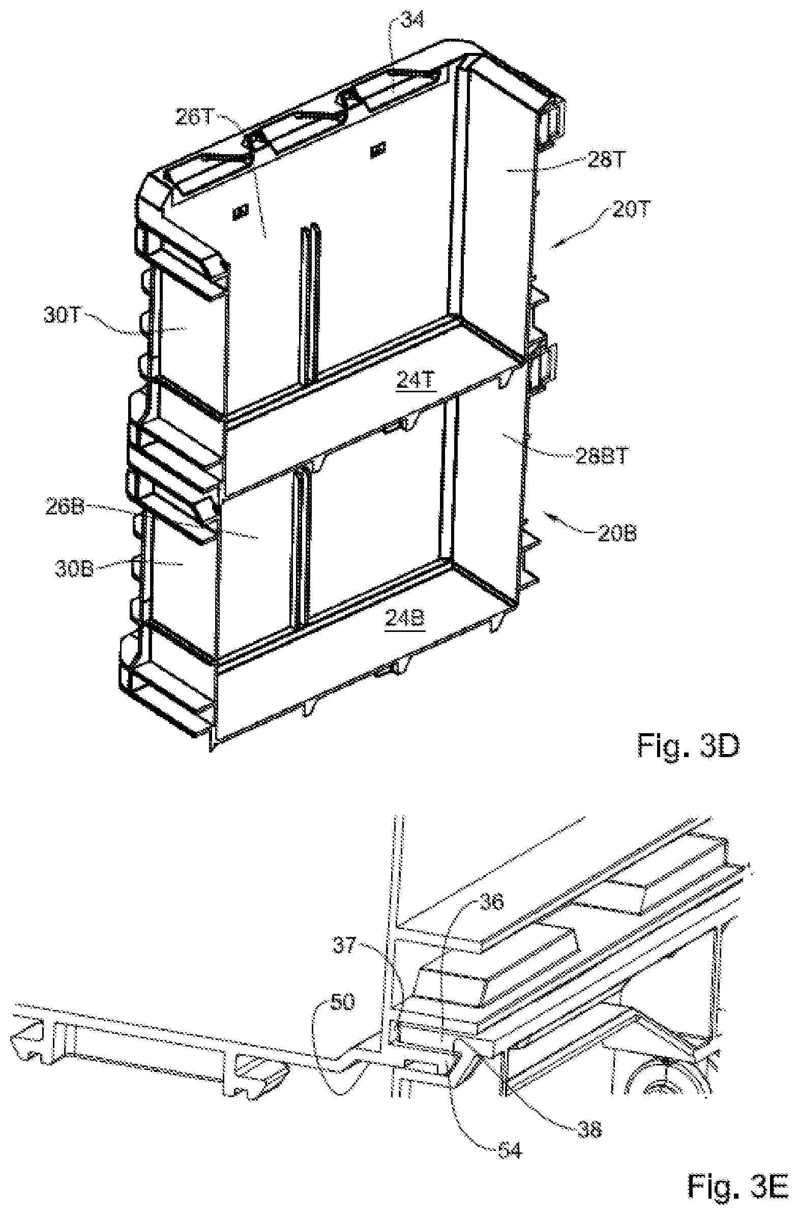
[0067] FIG. 3D is section along line V-V in FIG. 3A;
[0068] FIG. 3E is section along line VI-VI in FIG. 3A;
[0069] FIG. 3F is section along line VII-VII in FIG. 3A;
[0070] FIG. 4A is a perspective front view of a crate according to the disclosure, articulated to a wall mounting plate, through an auxiliary coupling;
[0071] FIG. 4B is a perspective rear view of the assembly of FIG. 4A;
[0072] FIG. 5 is perspective view of the wall mounting plate of FIG. 4A;
[0073] FIG. 6A is an enlarged section along line VII-VII in FIG. 4B; and
[0074] FIG. 6B is an enlarged section along line VIII-VIII in FIG. 4B.
DETAILED DESCRIPTION OF EMBODIMENTS
[0075] Attention is first directed to FIGS. 1A to 2C, directed to a crate according to the present disclosure, generally designated 20. The crate 20 is a rectangle shaped open top crate, made of molded resin and comprises a base 24 from which four side-walls upwardly extend, of which two opposite side-walls are referred to as locking side-walls 26, a back wall 28 extending at a rear of the crate, between the locking side-walls 26, and a front wall, between the locking side-walls 26, referred to as a third wall 30.
[0076] The two locking side-walls 26 are each configured at their top faces 26A and 26B, respectively, with three female coupling depressions, namely sliding locking slots 34, disposed parallel and along the top face of each locking side-wall 26, and each slot configured with an arresting rib 36, a top surface thereof extending substantially flush with the top faces 26A and 26B, respectively, such that the arresting rib 36 forms an undercut portion 38 therebelow (best seen in FIG. 2A), for arresting a respective coupling male member as will be discussed hereinafter. It is further seen that each of the sliding locking slots 34 is configured with an uncovered portion extending behind arresting rib 36, serving as a receiving bay 40 for a male coupling tongue, as will follow. The sliding locking slots 34 constitute female coupling members of a male-female coupling system.
[0077] The sliding locking slots are disposed parallelly along a sliding path (also referred to as an engaging path) extends in direction from the third wall 30 to the back wall 28, as represented by arrow 35.
[0078] Also extending from the top faces 26A and 26B, respectively, there are protuberances 46 (two disposed on each side-wall), said protuberances configured with a substantially upright outside-facing surface 48 and an inclined inside-facing surface 49. The purpose of said protuberances 46 will become apparent upon discussing stacking of crates.
[0079] The crate 20 is further configured, at each bottom surface 50 of the locking side-walls 26A and 26B, with several locking tongues 54 (three in the illustrated example in correspondence with the three sliding locking slots 34), parallelly extending and disposed along said sliding path 35. Each of the locking tongues 54 is open in a direction facing the back wall, with a space 37 above each tongue, wherein the shape and size of each locking tongues 54 is configured for receiving within the receiving bay 40 namely sliding locking slots 34, and further for sliding engagement with the arresting rib 36, wherein the locking tongues 54 constitute male coupling members of a male-female coupling system. The space 37 is sufficient for receiving the arresting rib 36.
[0080] Further configured at a bottom of the third wall 30 of crate 20, there is a locking latch assembly 60 comprising a double walled cavity 62 extending between an external wall surface 64 of the third wall 30, and an inside wall surface 66 thereof, with an inside-protruding housing 68 within the inside space of the crate. The locking latch assembly 60 comprises a locking latch 70, biased by a biasing member 72 within the cavity 62, such that a locking tip 78 of the locking latch 70 normally projects from bottom surface 24B of bottom wall 24 (FIG. 2C). The external wall surface 64 of the third wall 30 is configured with a window 82 allowing access to a manipulating recess 84 of the locking latch 70, facilitating manual manipulating thereof between the normally projecting position (engaged, locked position), and a temporarily axially displaced position, wherein the locking tip 78 is flush or above the bottom face of the bottom wall 24 (disengaged, unlocked position). The arrangement is such that at the projecting position the locking tip 78 is configured for bearing against an inside wall surface 30B of the third wall 30 (FIG. 3C).
[0081] As will become apparent hereafter, the object of the locking latch assembly 60 is to prevent sliding displacement of a top, stacked crate, over a bottom crate along said sliding path 35, whilst the male-female coupling members provide articulation of the stacked crates so as to prevent their separation in a vertical direction.
[0082] At a top end of the third wall 30, at a location above the locking latch assembly 60, there is a ribbed gliding ramp 88 configured for guidance of the locking latch into latch arresting portion, namely at the location 75 (FIGS. 1D and 3C) bearing against the inside wall surface 30B of the third wall 30 (FIG. 3C).
[0083] Further reference is now being made also to FIGS. 3A to 3F, showing stacking of two crates above one another, the two crates being similar to one another and are the same as crate 20 illustrated herein, and are designated 20T (top crate) and 20B (bottom crate), respectively. Likewise, the respective elements of these crates are given like reference numbers as above, however annotated T and B to indicate Top and Bottom, respectively.
[0084] For stacking the crates, the top crate 20T is placed over the bottom crate 20B at a partially overlapping position, such that the locking side-walls 26T of the top crate are coplanar with the locking side-walls 26B of the bottom crate, however with the third wall 30T of the top crate disposed slightly before the third wall 30B of the bottom crate, allowing the locking tongues 54 of the top crate to nest within the receiving bay 40. Then, the top crate 20T is slidingly displaced forwards, i.e. along the sliding path 35, namely towards the back wall 28, whereupon the as the locking tongues 54 engage under the arresting ribs 36 the locking tip 78 of locking latch 70 of the top crate slides over the gliding ramp 88, causing the locking latch 70 to temporarily retract and facilitating further sliding displacement of the top crate 20T over the bottom crate 20B, until the containers are flush on top of one another (FIGS. 3A-3F), whereby the locking latch 70 can spontaneously displace into its normally projecting position and engage the latch arresting portion 75 (at the inner surface of the third wall 30B of the bottom crate 20B). Once coupled, the crates 20T and 20B are securely articulated to one another and will not detach unless the locking latch 70 of the top crate is displaced to retract, facilitating sliding displacement of the top crate along the sliding path, though at a reverse sense, whereby the crates are no uncoupled.
[0085] Reverting now to the protuberances 46 extending from the top faces 26A and 26B, respectively (of the bottom crate 20B), these are configured for engaging within an upright wall surface 89 of a depression disposed in register at a bottom surface of the top crate 20T stacked above, to thereby prevent outwards buckling of the locking side-walls 26B of a bottom crate 20B, as might have occurred under load.
[0086] According to another aspect of the present disclosure, and with further reference now being made also to FIGS. 4A to 6B, the crate 20 is further configured with an auxiliary coupling arrangement. The auxiliary coupling arrangement comprises a first auxiliary coupling arrangement 100 (best seen in FIG. 1D) configured at outside face of the back wall 28 of the crate, and a second auxiliary coupling arrangement 110 configured at the bottom face of the base 24 of the crate.
[0087] Whilst the a first auxiliary coupling arrangement 100 is configured only on the back wall 28, it is appreciated that it could just as well be configured on any other side-wall of the crate. Furthermore, the crate 20 can exclude any auxiliary coupling arrangement, or it can be configured with any one or more of the first auxiliary coupling arrangement 100 and the second auxiliary coupling arrangement 110.
[0088] Both the first auxiliary coupling arrangement 100 and the second auxiliary coupling arrangement 110 are configured with a plurality of male coupling members 102 and 112, respectively, of male-female slider coupler type arrangements. The auxiliary male coupling members 102 and 112 are configured for sliding coupling engagement with corresponding female coupling members 122 of a male-female slider coupler, e.g. of a mounting plate 130 (best seen in FIG. 5). The auxiliary male coupling members 112 and 122 are configured with a female-engaging portion projecting from an outside face of the crate and comprising at least one (two in the illustrations) locking tongues 114 projecting laterally outwardly from the female-engaging portion, and configured for sliding engagement with inwardly-directed arresting ribs 124 of the female coupling members 122 of the mounting plate 130, wherein coupling engagement takes place along an auxiliary sliding path 125.
[0089] In addition, the back wall 28 is configured with a female coupler member 128 (best seen in FIG. 1B), for sliding arresting (along said sliding path 125) with a corresponding male coupling member 131 being an elongate member configured with two laterally projecting coupling ribs 133.
[0090] The male-female coupling array disposed on the mounting plate 130 and the first auxiliary coupling arrangement 100 and the second auxiliary coupling arrangement 110 of the crate 20 are disposed so as to facilitate mounting of the crate to the mounting plate 130 either through the first auxiliary coupling arrangement 100 or through the second auxiliary coupling arrangement 110.
[0091] It is thus appreciated that the crate 20 can be mounted on a mounting member 130 with the crate opening oriented at any direction. The following are crate mounting examples: [0092] the crate can be articulated to a ceiling mounted plate, at a suspended fashion, through coupling of the locking side-walls to the ceiling mounted plate, with the crate's opening facing the ceiling (i.e. facing upwards); [0093] the crate can be articulated to a ceiling mounted plate, at a suspended fashion, through an auxiliary coupling arrangement configured at an outside wall of the crate (i.e. with the crate's base extending substantially normal to the ceiling and the crate's opening facing a wall); [0094] the crate can be articulated to a surface mounted plate fixed to any bearing surface, through an auxiliary coupling arrangement configured at the base of the crate, (i.e. with the crate's opening facing substantially upwards, normal to said surface mounted plate); [0095] the crate can be articulated to a wall mounted plate (e.g. vertically extending mounting plate), through an auxiliary coupling arrangement configured on an outside face of one or more of any of the side-walls of the crate at an outside wall of the crate (i.e. with the crate's base extending substantially normal to the wall mounted plate and the crate's opening facing a ceiling); and [0096] the crate can be articulated to a wall mounted plate (e.g. vertically extending mounting plate), through an auxiliary coupling arrangement configured on base of the crate (i.e. with the crate's base extending substantially parallel to the wall mounted plate and the crate's opening facing sideward).
* * * * *
D00000
D00001
D00002
D00003
D00004
D00005
D00006
D00007
D00008
D00009
D00010
D00011
XML
uspto.report is an independent third-party trademark research tool that is not affiliated, endorsed, or sponsored by the United States Patent and Trademark Office (USPTO) or any other governmental organization. The information provided by uspto.report is based on publicly available data at the time of writing and is intended for informational purposes only.
While we strive to provide accurate and up-to-date information, we do not guarantee the accuracy, completeness, reliability, or suitability of the information displayed on this site. The use of this site is at your own risk. Any reliance you place on such information is therefore strictly at your own risk.
All official trademark data, including owner information, should be verified by visiting the official USPTO website at www.uspto.gov. This site is not intended to replace professional legal advice and should not be used as a substitute for consulting with a legal professional who is knowledgeable about trademark law.