Airbag Module For Protecting The Head
Heigl; Jurgen ; et al.
U.S. patent application number 15/999595 was filed with the patent office on 2021-02-11 for airbag module for protecting the head. The applicant listed for this patent is TRW AUTOMOTIVE GMBH. Invention is credited to Robert Disam, Jurgen Heigl, Michael Rieger, Steffen Seidel, Hans-Joachim Tietze.
| Application Number | 20210039580 15/999595 |
| Document ID | / |
| Family ID | 1000005208030 |
| Filed Date | 2021-02-11 |

| United States Patent Application | 20210039580 |
| Kind Code | A1 |
| Heigl; Jurgen ; et al. | February 11, 2021 |
AIRBAG MODULE FOR PROTECTING THE HEAD
Abstract
A head protection airbag module comprising a tubular inflator, a holder for the inflator and an airbag which is in fluid communication with the inflator and is folded to form a package, characterized by a guide element for the airbag which is arranged on the holder and includes a guide tongue extending into the airbag package.
| Inventors: | Heigl; Jurgen; (Bobingen, DE) ; Tietze; Hans-Joachim; (Hans-Joachim, DE) ; Disam; Robert; (Mutlangen, DE) ; Seidel; Steffen; (Mutlangen, DE) ; Rieger; Michael; (Rechberghausen, DE) | ||||||||||
| Applicant: |
|
||||||||||
|---|---|---|---|---|---|---|---|---|---|---|---|
| Family ID: | 1000005208030 | ||||||||||
| Appl. No.: | 15/999595 | ||||||||||
| Filed: | February 15, 2017 | ||||||||||
| PCT Filed: | February 15, 2017 | ||||||||||
| PCT NO: | PCT/EP2017/053387 | ||||||||||
| 371 Date: | August 20, 2018 |
| Current U.S. Class: | 1/1 |
| Current CPC Class: | B60R 21/237 20130101; B60R 21/213 20130101; B60R 21/231 20130101; B60R 2021/0048 20130101; B60R 21/2171 20130101; B60R 21/2176 20130101; B60R 2021/161 20130101; B60R 21/232 20130101 |
| International Class: | B60R 21/217 20060101 B60R021/217; B60R 21/231 20060101 B60R021/231; B60R 21/237 20060101 B60R021/237 |
Foreign Application Data
| Date | Code | Application Number |
|---|---|---|
| Feb 19, 2016 | DE | 10 2016 001 942.5 |
Claims
1-9. (canceled)
10. A head protection airbag module comprising a tubular inflator (5), a holder (10) for the inflator (5) and an airbag (7) which is in fluid communication with the inflator (5) and is folded to form a package (20), wherein a guide element (12) for the airbag (7) is arranged on the holder (10) and includes a guide tongue (18) extending into the airbag package (20).
11. The airbag module according to claim 10, wherein the guide element (12) includes a body portion (14) which extends tangentially to the inflator (5).
12. The airbag module according to claim 11, wherein the guide tongue (18) extends approximately perpendicularly to the body portion (14) on the side where also the inflator (5) is located.
13. The airbag module according to claim 10, wherein the guide element (12) is clamped between the holder (10) and the inflator (5).
14. The airbag module according to claim 10, wherein the guide element (12) includes two retaining lands (16) located on the either side of the holder (10).
15. The airbag module according to claim 10, wherein the airbag package (20) includes an inflator-side portion (24) and a main portion (22), wherein the major part of the wall of the airbag (7) is located in the main portion (22) and the guide tongue (18) protrudes into the airbag package (20) between the inflator-side portion (24) and the main portion (22).
16. The airbag module according to claim 15, wherein the airbag (7) is rolled in the main portion (22).
17. The airbag module according to claim 15, wherein the airbag (7) is folded into superposed folds in the main portion (22).
18. The airbag module according to claim 15, wherein the inflator-side portion (24) of the airbag package (20) comprises of one to five folds of the airbag wall.
Description
RELATED APPLICATIONS
[0001] This application corresponds to PCT/EP2017/053387, filed Feb. 15, 2017, which claims the benefit of German Application No. 10 2016 001 942.5 filed Feb. 19, 2016, the subject matter of which are incorporated herein by reference in their entirety.
BACKGROUND OF THE INVENTION
[0002] The invention relates to a head protection airbag module comprising a tubular inflator, a holder for the inflator and an airbag being in fluid communication with the inflator and being folded into a package.
[0003] Such airbag module is disposed along the outer edge of a roof of an automotive vehicle so that, after the inflator having been ignited, the airbag deploys along the inside of the windows of the vehicle. Accordingly, the airbag may extend from the A-pillar of the vehicle to the C-pillar in the deployed state.
[0004] In order to enable the airbag to deploy in the desired direction it is important that it is arranged as precisely as possible at the roof. To this end, fastening clips can be used. In DE 20 2014 003 512 an example of such fastening clip is found.
[0005] It is also known to fix the airbag package by tape on the holder of the inflator.
SUMMARY OF THE INVENTION
[0006] It is the object of the invention to align the airbag package even more precisely.
[0007] In order to achieve said object, in an airbag module of the type mentioned in the beginning a guide element for the airbag is provided which is arranged on the holder and includes a guide tongue extending into the airbag package. This helps to specifically align the folds of the airbag package in the vicinity of the inflator, thus causing the initial deployment of the airbag in the area of the inflator to become more robust. It is of particular advantage that the guide element itself is precisely aligned by being arranged on the holder of the inflator which in turn is arranged on the vehicle body and thus can reliably serve as reference surface. The spatial orientation and, resp., angular position of the guide element and/or the spatial orientation and, resp., angular position of the guide tongue may help to influence the direction of deployment and to reach improved reproducibility of the deployment of the airbag.
[0008] In accordance with one embodiment of the invention, the guide element is provided to include a body portion that extends tangentially to the inflator. In this way, the airbag package is arranged precisely below the inflator.
[0009] Preferably, the guide tongue extends approximately perpendicularly to the body portion on the side on which also the inflator is provided. In this way, the airbag package is subdivided into a portion close to the inflator and a portion distant from the inflator, which allows to specifically influence the start of the deployment operation in the desired way.
[0010] Depending on the deployment direction to be obtained, the guide tongue may as well be arranged at an angle deviating from the right angle related to the body portion.
[0011] The guide tongue backs the defined position of the portion close to the inflator of the airbag package, thus causing above all the first deployment phase of the airbag to be specifically controlled. The portion of the airbag package close to the inflator in this case has the function of a (single-layer or multi-layer) ejecting fold which is filled first and controls the early deployment behavior.
[0012] According to a preferred configuration, it is provided that the guide element is clamped between the holder and the inflator. In this way, the guide element is reliably held with little effort.
[0013] Preferably, the guide element includes two retaining lands located on the one side and the other side of the holder. Retaining lands are used to achieve mechanical positive fixation of the guide element to the holder.
[0014] In accordance with a preferred embodiment, the airbag package is provided to include an inflator-side portion and a main portion, wherein the major part of the wall of the airbag is located in the main portion and the guide tongue protrudes into the airbag package between the inflator-side portion and the main portion. In this way, specifically only the start of the deployment operation is influenced, while the major part of the wall of the airbag can deploy without being disturbed by the guide element. The inflator-side portion of the airbag package may consist of one to five folds of the airbag wall.
[0015] The airbag may be rolled or else be folded to form superposed folds in the main portion. Both types of folding result in the desired influence of the guide tongue on the start of the deployment operation.
BRIEF DESCRIPTION OF THE DRAWINGS
[0016] In the following, the invention shall be described by way of different embodiments shown in the enclosed drawings, wherein:
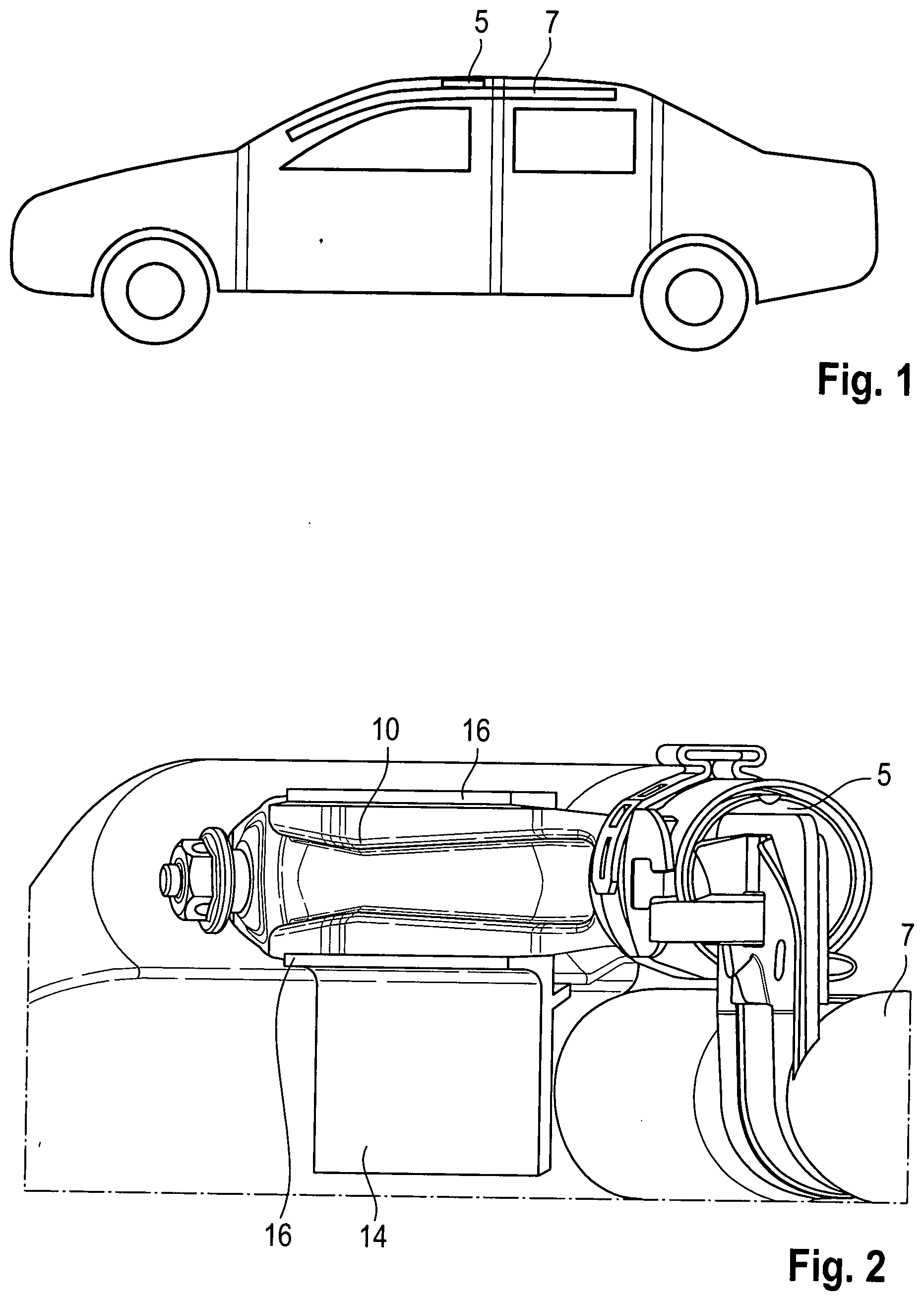
[0017] FIG. 1 schematically shows a side view of an automotive vehicle provided with a head protection airbag module according to the invention;
[0018] FIG. 2 shows a perspective broken view of a head protection airbag module according to the invention;
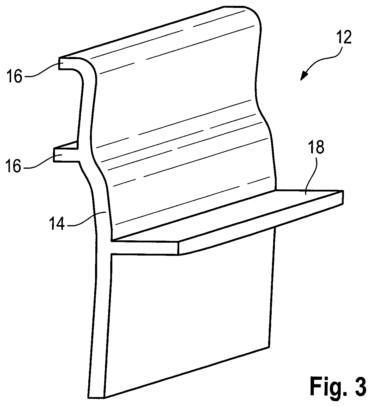
[0019] FIG. 3 shows a perspective view of a guide element used in the head protection airbag module according to the invention;
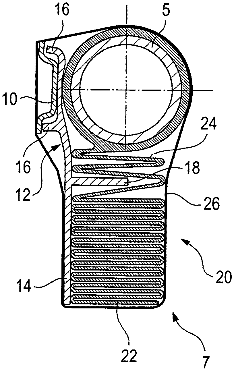
[0020] FIG. 4 shows a sectional view of the head protection airbag module of FIG. 1 with a first variant of the folded airbag; and
[0021] FIG. 5 shows a sectional view of the head protection airbag module of FIG. 1 with a second variant of the folded airbag.
DESCRIPTION
[0022] FIG. 1 schematically illustrates a vehicle 1 provided with two head protection airbag modules 2 only one of which is visible in FIG. 1.
[0023] Each head protection airbag module extends along the lateral edge of a roof in the vehicle interior and as substantial components includes an inflator 5 and an airbag 7. The airbag may be deployed starting from a folded position so that it will extend over at least part of the side windows of the vehicle and approximately from an A-pillar via the B-pillar to the C-pillar.
[0024] In FIG. 2, the inflator 5 which is arranged on a holder 10 is visible. The inflator 5 is connected to the vehicle body by means of the holder 10. The inflator 5 is shown in FIG. 5 by the example of a so-called center module, i.e. the inflator is disposed in a central area of the airbag module, wherein the gas flow is guided through elements known per se into the front and rear parts of the airbag 7. However, it is equally possible to design the airbag module as a module filled at the end side, i.e. at the front or rear side, with the inflator being arranged at the front-side or rear-side end of the airbag module in that case.
[0025] Between the holder 10 and the inflator 5 a guide element 12 for the airbag 7 is arranged (cf. also FIG. 3). Said guide element includes a body portion 14 which is configured as a flat plate in the broadest sense.
[0026] At one end (at the top in FIG. 3) the body portion is provided with two retaining lands 16. They are located on either side of the holder 10 of the inflator 5, with the upper end of the body portion 14 being clamped between the holder 10 and the inflator 5. The guide element 12 thus abuts quasi positively on the holder 10. In this way, the body portion is provided at a defined position relative to the inflator and to the holder. Since the holder is provided at a defined position relative to the vehicle body, thus also the guide element in total is aligned with the vehicle body in a precise and defined manner. The retaining lands prevent tilting about an axis that is perpendicular to the body portion 14, and the full-surface contact with the holder 10 prevents tilting about an axis which extends in parallel to the longitudinal axis of the tubular inflator 5.
[0027] The body portion 14 includes a guide tongue 18 extending approximately perpendicularly to the body portion 14 on the side being opposed to the retaining lands 16. The guide tongue 18 is located below the retaining lands 16 so far that a distance is resulting between the guide tongue 18 and the lower edge of the inflator 5 (see FIG. 4).
[0028] In FIG. 4, furthermore the folded airbag 7 is evident which forms an airbag package 20. The guide tongue 18 extends into said airbag package so that on the side of the guide tongue 18 facing away from the inflator a main portion 22 of the airbag package 20 is formed and between the inflator 5 and the guide tongue 18 an inflator-side portion 24 of the airbag package 20 is formed.
[0029] The portion 24 of the airbag package is formed of three to four (double-walled) folds of the airbag 7. The main portion 22 consists of the remaining wall of the airbag 7 which is superposed in folds.
[0030] In this case, a wrapping 26 which fixes the airbag 7 in the folded state and may also serve as a protection against environmental influences extends around the airbag module.
[0031] FIG. 5 illustrates a variant. For the features known from the embodiment shown in FIG. 4 the same reference numerals are used and, in this respect, the foregoing explanations are referred to.
[0032] The variant shown in FIG. 5 differs from the embodiment shown in FIG. 4 by the folding of the airbag 7 and by the inflator-side portion 24 of the airbag package 20.
[0033] The main portion 22 of the airbag package 20 in this case is folded by means of rolled folding.
[0034] The inflator-side portion 24 of the airbag package 20 here consists of one single fold.
[0035] The guide element 12 ensures the airbag package 20 to be precisely aligned in the area of the inflator. The guide tongue provides for the start of the deployment operation to be more robust, i.e. to take place with smaller tolerances. This helps to ensure more precisely the direction in which the airbag 7 will deploy.
* * * * *
D00000
D00001
D00002
D00003
XML
uspto.report is an independent third-party trademark research tool that is not affiliated, endorsed, or sponsored by the United States Patent and Trademark Office (USPTO) or any other governmental organization. The information provided by uspto.report is based on publicly available data at the time of writing and is intended for informational purposes only.
While we strive to provide accurate and up-to-date information, we do not guarantee the accuracy, completeness, reliability, or suitability of the information displayed on this site. The use of this site is at your own risk. Any reliance you place on such information is therefore strictly at your own risk.
All official trademark data, including owner information, should be verified by visiting the official USPTO website at www.uspto.gov. This site is not intended to replace professional legal advice and should not be used as a substitute for consulting with a legal professional who is knowledgeable about trademark law.