Polishing Apparatus And Retainer Ring
KAWASAKI; Takahiko
U.S. patent application number 16/806216 was filed with the patent office on 2021-02-11 for polishing apparatus and retainer ring. This patent application is currently assigned to KIOXIA CORPORATION. The applicant listed for this patent is KIOXIA CORPORATION. Invention is credited to Takahiko KAWASAKI.
| Application Number | 20210039224 16/806216 |
| Document ID | / |
| Family ID | 1000004720280 |
| Filed Date | 2021-02-11 |


| United States Patent Application | 20210039224 |
| Kind Code | A1 |
| KAWASAKI; Takahiko | February 11, 2021 |
POLISHING APPARATUS AND RETAINER RING
Abstract
According to one embodiment, a polishing apparatus includes a polishing head having a retainer surrounding a substrate to be polished, and a polishing pad facing the polishing head. The retainer includes a first material and a second material. The first material contains at least one of aromatic polyamide, polyphenylene sulfide, polyetherimide, polyamideimide, polyetheretherketone, or polybenzimidazole. The second material contains a fluororesin.
| Inventors: | KAWASAKI; Takahiko; (Yokohama Kanagawa, JP) | ||||||||||
| Applicant: |
|
||||||||||
|---|---|---|---|---|---|---|---|---|---|---|---|
| Assignee: | KIOXIA CORPORATION Tokyo JP |
||||||||||
| Family ID: | 1000004720280 | ||||||||||
| Appl. No.: | 16/806216 | ||||||||||
| Filed: | March 2, 2020 |
| Current U.S. Class: | 1/1 |
| Current CPC Class: | B24B 37/32 20130101; B24B 37/24 20130101; B24B 37/0053 20130101 |
| International Class: | B24B 37/32 20060101 B24B037/32; B24B 37/24 20060101 B24B037/24 |
Foreign Application Data
| Date | Code | Application Number |
|---|---|---|
| Aug 8, 2019 | JP | 2019-146541 |
Claims
1. A polishing apparatus comprising: a polishing head having a retainer surrounding a substrate to be polished; and a polishing pad facing the polishing head, wherein the retainer includes a first material and a second material, wherein the first material contains at least one of aromatic polyamide, polyphenylene sulfide, polyetherimide, polyamideimide, polyetheretherketone (PEEK), or polybenzimidazole, and wherein the second material contains a fluororesin.
2. The polishing apparatus according to claim 1, wherein a weight percentage of the second material with respect to the first material is 1% to 10%.
3. The polishing apparatus according to claim 1, wherein the fluororesin of the second material includes at least one of polytetrafluoroethylene (PTFE), perfluoroalkoxyalkane (PFA), a perfluoroethylene propene copolymer (FEP), an ethylene tetrafluoroethylene copolymer (ETFE), polyvinylidene fluoride (PVDF), polychlorotrifluoroethylene (PCTFE), ethylene chlorotrifluoroethylene copolymer (ECTFE), tetrafluoroethylene-perfluorodioxole copolymer (TFE/PDD), or polyvinyl fluoride (PVF).
4. The polishing apparatus according to claim 3, wherein the first material contains PEEK and the fluororesin of the second material includes PTFE, and wherein the weight of PTFE with respect to the weight of PEEK is 1% to 20%.
5. The polishing apparatus according to claim 1, wherein the retainer is a retainer ring.
6. A retainer ring for use a polishing head for holding a substrate to be polished, the retainer ring comprising: a first material and a second material, wherein the first material contains at least one of aromatic polyamide, polyphenylene sulfide, polyetherimide, polyamideimide, polyetheretherketone (PEEK), or polybenzimidazole, and wherein the second material contains a fluororesin.
7. The retainer ring according to claim 6, wherein a weight percentage of the second material with respect to the first material is 1% to 10%.
8. The retainer ring according to claim 6, wherein the fluororesin includes at least one of polytetrafluoroethylene (PTFE), perfluoroalkoxyalkane (PFA), a perfluoroethylene propene copolymer (FEP), an ethylene tetrafluoroethylene copolymer (ETFE), polyvinylidene fluoride (PVDF), polychlorotrifluoroethylene (PCTFE), ethylene chlorotrifluoroethylene copolymer (ECTFE), tetrafluoroethylene-perfluorodioxole copolymer (TFE/PDD), or polyvinyl fluoride (PVF).
9. The retainer ring according to claim 8, wherein the first material contains PEEK and the fluororesin of the second material includes PTFE, and wherein the weight of PTFE with respect to the weight of PEEK is 1% to 20%.
10. A polishing head comprising the retainer ring of claim 6.
11. A polishing head comprising the retainer ring of claim 7.
Description
CROSS-REFERENCE TO RELATED APPLICATION
[0001] This application claims the benefit of and priority to Japanese Patent Application No. 2019-0146541, filed Aug. 8, 2019, the entire contents of which are incorporated herein by reference.
FIELD
[0002] Embodiments described herein relate generally to a polishing apparatus and a retainer ring.
BACKGROUND
[0003] In a polishing apparatus used for chemical mechanical polishing (CMP), a substrate (wafer) is generally pressed against a polishing pad while being held by a polishing head. Subsequently, when the polishing head and the polishing pad are rotated, a film formed on a substrate surface is planarized.
[0004] The polishing head is generally provided with a retainer ring that surrounds the substrate in the circumferential direction. This retainer ring can prevent the substrate from jumping out of the polishing head during polishing.
[0005] The retainer ring is pressed against the polishing pad in the same manner as the substrate. For this reason, the retainer ring also wears with the polishing of the wafer substrate. Since the retainer ring is generally made of resin, wear progresses quickly. As a result, the replacement frequency of the retainer ring is increased.
DESCRIPTION OF THE DRAWINGS
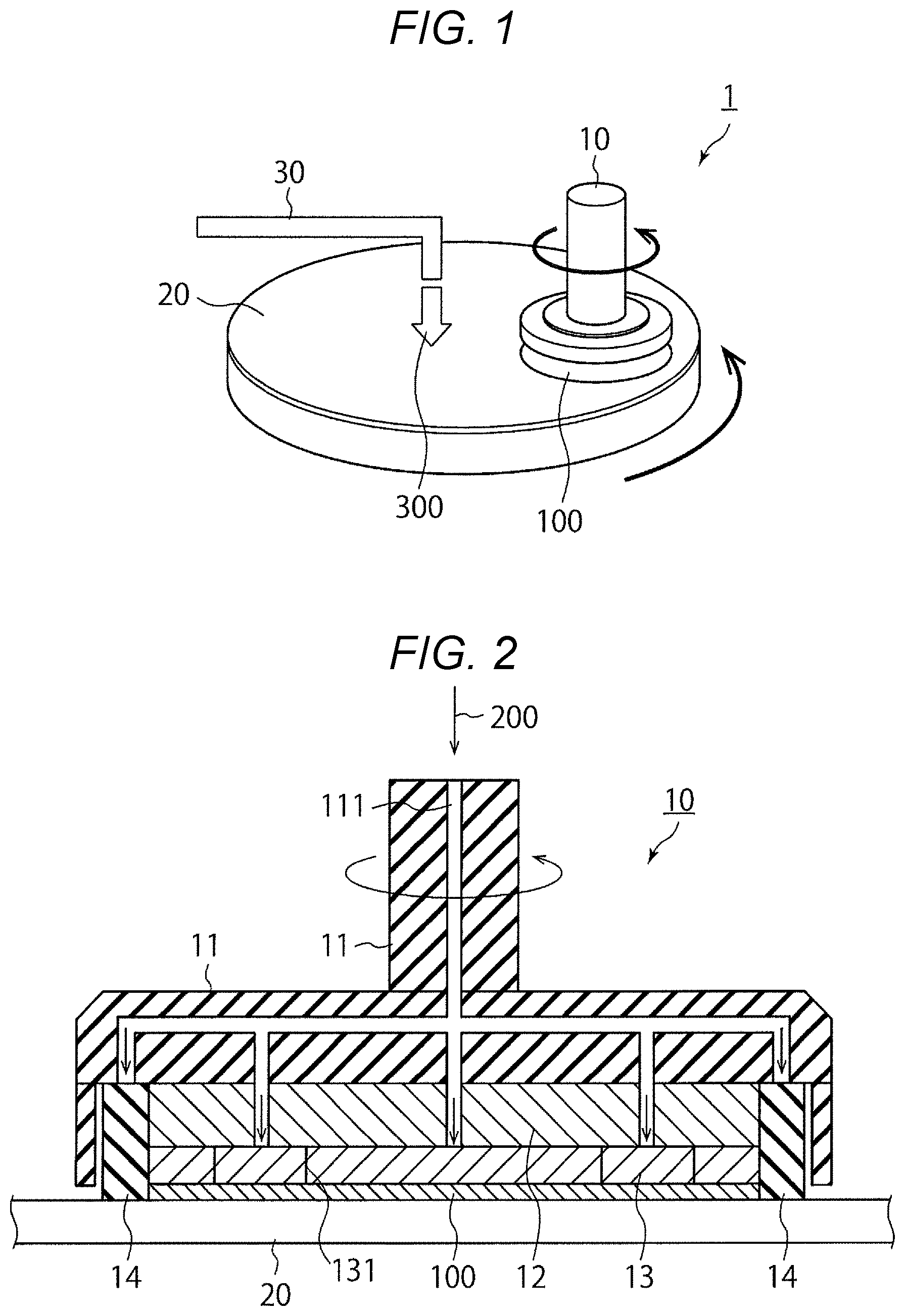
[0006] FIG. 1 is a schematic diagram illustrating a schematic configuration of a polishing apparatus according to an embodiment.
[0007] FIG. 2 is a sectional view of a polishing head.
[0008] FIG. 3 is a diagram of a retainer ring as seen from a bottom side.
[0009] FIG. 4 is a graph illustrating a relationship between a material of the retainer ring and an abrasion loss.
[0010] FIG. 5 is a graph illustrating a polishing rate and uniformity of a substrate for each material of the retainer ring.
DETAILED DESCRIPTION
[0011] Embodiments provide a polishing apparatus which can reduce abrasion of a retainer ring.
[0012] In general, according to one embodiment, there is provided a polishing apparatus including a polishing head having a retainer ring surrounding a substrate to be polished, and a polishing pad facing the polishing head. The retainer ring may include a first material and a second material. The first material may contain at least one of aromatic polyamide, polyphenylene sulfide, polyetherimide, polyamideimide, polyetheretherketone, and polybenzimidazole. The second material may contain a fluororesin. The weight percentage of the second material with respect to the first material may be 1% to 10%.
[0013] Hereinafter, embodiments of the present disclosure will be described with reference to the drawings. The present embodiment is not intended to limit the present disclosure.
[0014] FIG. 1 is a schematic diagram illustrating a schematic configuration of a polishing apparatus according to an embodiment. A polishing apparatus 1 as illustrated in FIG. 1 includes a polishing head 10, a polishing pad 20, and a nozzle 30. This polishing apparatus 1 may be used in a process of chemical mechanical polishing a substrate 100 in a wafer state.
[0015] FIG. 2 is a sectional view of the polishing head 10. As illustrated in FIG. 2, the polishing head 10 includes a support 11, a chucking plate 12, an elastic member 13, and a retainer ring 14. In some embodiments, a retainer ring 14 may be replaced by a retainer having a shape other than a ring.
[0016] The support 11 may be made of, for example, a resin, and a pipe 111 is formed therein. The pipe 111 is branched, and a part of a branch path extends to the chucking plate 12. The chucking plate 12 may be a ceramic disk, for example, and is provided in a lower portion of the support 11. The elastic member 13 may be rubber, for example, and is provided in the lower portion of the chucking plate 12. The elastic member 13 is divided into a plurality of regions by a plate-like member 131 provided corresponding to the branch path of the pipe 111.
[0017] In the polishing head 10, the pressure due to air 200 flowing into the pipe 111 may be applied to the substrate 100 through the elastic member 13, so that the substrate 100 is pressed against the polishing pad 20. In the present embodiment, since the pipe 111 is branched and the elastic member 13 is partitioned by the plate-like member 131, for example, a force applied to a central portion and an end portion of the substrate 100 can be adjusted.
[0018] As illustrated in FIG. 2, the retainer ring 14 is provided at the lower portion of the support 11 so as to surround the substrate 100, the chucking plate 12, and the elastic member 13. The retainer ring 14 may be pressed against the polishing pad 20 by the air 200 introduced into the pipe 111.
[0019] FIG. 3 is a diagram of the retainer ring 14 as seen from a bottom side. As illustrated in FIG. 3, grooves 141 are formed radially on a bottom surface of the retainer ring 14, in other words, on a contact surface with the polishing pad 20. When the retainer ring 14 is pressed against the polishing pad 20 by the groove 141, a gap is formed between them. Through this gap, a slurry 300 (see FIG. 1) can flow into and out of the retainer ring 14.
[0020] As illustrated in FIG. 1, the polishing pad 20 is positioned at a position facing the polishing head 10. In addition, a planar area of the polishing pad 20 is larger than a planar area of the substrate 100. The slurry 300 containing abrasive grains is supplied to the surface of the polishing pad 20.
[0021] The nozzle 30 discharges the slurry 300 from above the polishing pad 20. The slurry 300 may be, for example, ceria slurry.
[0022] Hereinafter, a process of chemically polishing a film formed on the substrate 100 using the above-described polishing apparatus 1 will be described. First, the nozzle 30 discharges the slurry 300 toward the surface of the polishing pad 20, and the polishing head 10 may press the film formed on the substrate 100 against the polishing pad 20.
[0023] Subsequently, the polishing head 10 and the polishing pad 20 may be simultaneously rotated in the same direction. As a result, a film embedded in the groove patterned on the surface of the substrate 100, such as an insulating film, a metal film, or a crystalline silicon film, may be planarized.
[0024] The rotation direction and rotation speed of the polishing head 10 and the polishing pad 20 may be appropriately set according to the film to be polished. That is, the rotation directions may be the same as or opposite to each other. Also, the rotational speeds may be the same as or different from each other.
[0025] In the present embodiment, the retainer ring 14 is provided along the outer periphery of the substrate 100 held by the polishing head 10. Therefore, even if a force for moving the substrate 100 to the outside of the polishing head 10 is generated with the rotation of the polishing head 10, the movement of the substrate 100 can be blocked by the retainer ring 14. Thereby, it is possible to prevent the substrate 100 from jumping out of the polishing head 10.
[0026] On the other hand, the retainer ring 14 may be pressed against the polishing pad 20 in the same manner as the substrate 100, and thus may be worn as the substrate 100 is polished.
[0027] In this embodiment, in order to reduce the wear of the retainer ring 14 accompanying polishing of the substrate 100, the retainer ring 14 may be formed of the first material containing a fluororesin. The first material may contain, for example, at least one of aromatic polyamide (PPA), polyphenylene sulfide (PPS), polyetherimide (PEI), polyamideimide (PAI), polyetheretherketone (PEEK), and polybenzimidazole (PBI). That is, the retainer ring 14 of the embodiment may include a plurality of types of materials exemplified above.
[0028] Examples of the fluororesin may include at least one of polytetrafluoroethylene (PTFE), perfluoroalkoxyalkane (PFA), a perfluoroethylene propene copolymer (FEP), an ethylene tetrafluoroethylene copolymer (ETFE), polyvinylidene fluoride (PVDF), polychlorotrifluoroethylene (PCTFE), ethylene chlorotrifluoroethylene copolymer (ECTFE), tetrafluoroethylene-perfluorodioxole copolymer (TFE/PDD), and polyvinyl fluoride (PVF). That is, the retainer ring 14 of the embodiment may include a plurality of types of fluororesins exemplified above.
[0029] It is considerable that the fluororesin is known to have a low friction coefficient on the surface thereof, and by using it as a material of the retainer ring 14, the friction coefficient between the retainer ring and the polishing pad can be reduced and the wear of the retainer ring can be reduced. Hereinafter, an appropriate amount range of the fluororesin added to the retainer ring 14 will be described with reference to FIGS. 4 and 5.
[0030] FIG. 4 is a graph illustrating a relationship between the material of the retainer ring and an abrasion loss. In FIG. 4, a horizontal axis indicates the material of the retainer ring 14 in which the additive amount of polytetrafluoroethylene (PTFE), which is an example of a fluororesin, is different. A vertical axis indicates abrasion loss (.mu.m) per hour of each material.
[0031] As illustrated in FIG. 4, if PTFE is not added to a thermoplastic engineering plastic material typified by a polyphenylene sulfide (PPS) resin or a polyether ether ketone (PEEK) resin, the abrasion loss of the retainer ring 14 is large. In this case, the life of the retainer ring 14 is shortened.
[0032] On the other hand, in a case where the weight percentage indicating the weight of PTFE with respect to the weight of the PEEK resin is 1% to 20%, the abrasion loss of the retainer ring 14 is reduced as illustrated in FIG. 4. The reason for this is that the frictional force generated between the retainer ring 14 and the polishing pad 20 is alleviated by adding PTFE.
[0033] FIG. 5 is a graph illustrating a polishing rate and uniformity of a substrate for each material of the retainer ring. In FIG. 5, the horizontal axis indicates the material of the retainer ring 14. The vertical axis on the left side indicates a polishing rate which is a polishing amount (nm) per minute at the center of the substrate 100. The vertical axis on the right side indicates the uniformity (%), which is a variation in polishing within the surface of the substrate 100. The polishing rate and the uniformity are indicated for the initial (first) substrate, 50.sup.th substrate, and 100.sup.th substrate out of 100 processed substrates 100.
[0034] As illustrated in FIG. 5, when the weight percentage of PTFE with respect to the PEEK resin is in a range of 1% to 10%, the polishing rate and the uniformity of the substrate 100 are as high as that of PPS not added with PTFE. On the other hand, when the weight percentage of PTFE exceeds 20%, the polishing rate is decreased as the number of processed substrates 100 are increased, and thereby the uniformity deteriorates. This is because the debris containing PTFE added to the retainer ring 14 is attached to the polishing pad and the abrasive grains and hinders polishing of the substrate 100.
[0035] Therefore, in consideration of the polishing rate and the uniformity of the substrate 100, it is desirable that the weight percentage of the fluororesin added to the retainer ring 14 is in the range of 1% to 10%.
[0036] According to the embodiment described above, the frictional force generated between the retainer ring 14 and the polishing pad 20 can be reduced by adding the fluororesin to the material of the retainer ring 14. With this, since the lifetime of the retainer ring 14 can become long, the replacement frequency of the retainer ring 14 can be reduced. Moreover, the polishing rate and the uniformity of the substrate 100 can be ensured by setting the weight percentage indicating a total weight of the fluororesin in the range of 1% to 10%, with respect to a total weight of aromatic polyamide (PPA), polyphenylene sulfide (PPS), polyetherimide (PEI), polyamideimide (PAI), polyetheretherketone (PEEK), and polybenzimidazole (PBI) which are the first materials.
[0037] In the embodiment, the retainer ring 14 is described as including the first material and the fluororesin. However, a material other than the first material and the fluororesin may be included. Even in that case, the total weight of the fluororesin with respect to the total weight of the first material may be set to be in a range of 1% to 10 weight percent.
[0038] While certain embodiments have been described, these embodiments have been presented by way of example only, and are not intended to limit the scope of the present disclosure. Indeed, the novel embodiments described herein may be embodied in a variety of other forms; furthermore, various omissions, substitutions and changes in the form of the embodiments described herein may be made without departing from the spirit of the present disclosure. The accompanying claims and their equivalents are intended to cover such forms or modifications as would fall within the scope and spirit of the present disclosure.
* * * * *
D00000
D00001
D00002
D00003
XML
uspto.report is an independent third-party trademark research tool that is not affiliated, endorsed, or sponsored by the United States Patent and Trademark Office (USPTO) or any other governmental organization. The information provided by uspto.report is based on publicly available data at the time of writing and is intended for informational purposes only.
While we strive to provide accurate and up-to-date information, we do not guarantee the accuracy, completeness, reliability, or suitability of the information displayed on this site. The use of this site is at your own risk. Any reliance you place on such information is therefore strictly at your own risk.
All official trademark data, including owner information, should be verified by visiting the official USPTO website at www.uspto.gov. This site is not intended to replace professional legal advice and should not be used as a substitute for consulting with a legal professional who is knowledgeable about trademark law.