Bumper With Viewing Window For Autonomous Cleaner
Sexton; Joseph ; et al.
U.S. patent application number 16/978001 was filed with the patent office on 2021-02-11 for bumper with viewing window for autonomous cleaner. The applicant listed for this patent is David KHALIL, Joseph SEXTON, TECHTRONIC FLOOR CARE TECHNOLOGY LIMITED. Invention is credited to David Khalil, Joseph Sexton.
| Application Number | 20210038033 16/978001 |
| Document ID | / |
| Family ID | 1000005209384 |
| Filed Date | 2021-02-11 |


View All Diagrams
| United States Patent Application | 20210038033 |
| Kind Code | A1 |
| Sexton; Joseph ; et al. | February 11, 2021 |
BUMPER WITH VIEWING WINDOW FOR AUTONOMOUS CLEANER
Abstract
An autonomous cleaner includes a body, a dust collection assembly including a dust inlet disposed interior of a perimeter of the body, a brush roll mounted adjacent the dust inlet and proximate a transparent or translucent portion of the dust inlet, a drive unit configured to move the body along a cleaning surface, a controller configured to control an autonomous operation of the drive unit, and a bumper operable to sense an impact mounted to and at least partially along the perimeter of the body. The bumper has at least one viewing window configured to allow a user to view the brush roll through the at least one viewing window and the transparent or translucent portion of the dust inlet.
| Inventors: | Sexton; Joseph; (Huntersville, NC) ; Khalil; David; (College Park, MD) | ||||||||||
| Applicant: |
|
||||||||||
|---|---|---|---|---|---|---|---|---|---|---|---|
| Family ID: | 1000005209384 | ||||||||||
| Appl. No.: | 16/978001 | ||||||||||
| Filed: | March 5, 2019 | ||||||||||
| PCT Filed: | March 5, 2019 | ||||||||||
| PCT NO: | PCT/US2019/020801 | ||||||||||
| 371 Date: | September 3, 2020 |
Related U.S. Patent Documents
| Application Number | Filing Date | Patent Number | ||
|---|---|---|---|---|
| 62639387 | Mar 6, 2018 | |||
| Current U.S. Class: | 1/1 |
| Current CPC Class: | A47L 2201/04 20130101; A47L 9/2889 20130101; A47L 9/009 20130101; A47L 2201/022 20130101; A47L 9/2826 20130101; A47L 9/0477 20130101 |
| International Class: | A47L 9/04 20060101 A47L009/04; A47L 9/28 20060101 A47L009/28; A47L 9/00 20060101 A47L009/00 |
Claims
1. An autonomous cleaner comprising: a body having a perimeter; a dust collection assembly including a dust inlet disposed interior of the perimeter and a brush roll mounted adjacent the dust inlet and proximate a transparent or translucent portion of the dust inlet; a drive unit configured to move the body along a cleaning surface; a controller configured to control an autonomous operation of the drive unit; and a bumper operable to sense an impact mounted to and at least partially along the perimeter of the body, the bumper having at least one viewing window configured to allow a user to view the brush roll through the at least one viewing window and the transparent or translucent portion of the dust inlet.
2. The autonomous cleaner of claim 1, wherein the at least one viewing window defines an aperture that extends through the bumper.
3. The autonomous cleaner of claim 1, wherein the at least one viewing window is formed from a transparent or translucent material.
4. The autonomous cleaner of claim 1, further comprising a suction motor configured for generating an air flow through the dust inlet.
5. The autonomous cleaner of claim 4, the dust collection assembly further comprising a dust collection chamber in communication with the dust inlet and the suction motor.
6. The autonomous cleaner of claim 1, the dust collection assembly further comprising a dust collection chamber proximate the dust inlet and brush roll configured for receiving dust swept by the brush roll.
7. The autonomous cleaner of claim 1, wherein the bumper defines a chamber configured to receive the transparent or translucent portion of the dust inlet therein.
8. The autonomous cleaner of claim 1, wherein the body further comprises a chassis configured to support the dust collection assembly at a front end of the autonomous cleaner, wherein the bumper is mounted to the body at the front end and the at least one viewing window is disposed adjacent the transparent or translucent portion of the dust collection assembly relative to the cleaning surface.
9. The autonomous cleaner of claim 1, wherein the bumper includes an opaque central portion and the at least one viewing window includes a pair of viewing windows that are formed on opposite sides of the opaque central portion.
10. The autonomous cleaner of claim 9, wherein the bumper includes a frame member having opposing first and second side walls, a neck body located between the first and second side walls, a first rear wall extending from the neck body toward the first side wall, a second rear wall extending from the neck body toward the second side wall, a first arcuate arm extending forwardly relative to the first rear wall and outwardly from the neck body to the first side wall and a second arcuate arm extending forwardly relative to the second rear wall and outwardly from the neck body to the second side wall, and wherein the at least one viewing window includes a first viewing window formed between the first arcuate arm and the first rear wall and a second viewing window formed between the second arcuate arm and the second rear wall.
11. The autonomous cleaner of claim 1, wherein the bumper includes a frame member having opposing first and second side walls and a rear wall extending from the first side wall extending toward the second side wall, and wherein the at least one viewing window includes a first viewing window provided in the frame member forwardly of the rear wall.
12. The autonomous cleaner of claim 11 further comprising a sensor operable in combination with the controller to sense a surrounding environment, the sensor being mounted to the body at the front end of the autonomous cleaner, wherein the rear wall of the bumper defines a pass-through opening that extends through the rear wall and is aligned with the sensor.
13. The autonomous cleaner of claim 1, wherein the dust inlet is proximate a forward portion of the perimeter of the body.
Description
CROSS-REFERENCE TO RELATED APPLICATIONS
[0001] This application claims priority to U.S. Provisional Patent Application No. 62/639,387 filed Mar. 6, 2018, the entire contents of which are hereby incorporated by reference herein.
BACKGROUND
[0002] The present disclosure relates to a bumper with a viewing window associated with an autonomous cleaner
[0003] Vacuum cleaners and sweepers generally use mechanical action and/or air flow to draw dust, dirt, or other debris from a surface. A vacuum cleaner typically draws a combination of air and dust, dirt, or other debris into the cleaner through a floor nozzle. This "dirty air" typically enters a dust separator in the vacuum that separates the dust, dirt, or debris from the air. A bin or bag collects the separated dust, dirt, or debris separated from the air for later disposal. The resulting "clean air" exits the dust separator where it is exhausted from the vacuum cleaner. A sweeper typically uses mechanical action to sweep dust, dirt, or other debris from a floor into the sweeper through a dirt inlet into a bin for later disposal. An autonomous cleaner may be a vacuum cleaner or sweeper that is configured to traverse and clean an area without requiring a user to operate.
SUMMARY
[0004] In some embodiments, the present disclosure relates to an autonomous cleaner. The autonomous cleaner comprises a body having a perimeter, a dust collection assembly including a dust inlet disposed interior of the perimeter and a brush roll mounted adjacent the dust inlet and proximate a transparent or translucent portion of the dust inlet, a drive unit configured to move the body along a cleaning surface, a controller configured to control an autonomous operation of the drive unit, and a bumper operable to sense an impact mounted to and at least partially along the perimeter of the body. The bumper has at least one viewing window configured to allow a user to view the brush roll through the at least one viewing window and the transparent or translucent portion of the dust inlet.
[0005] Other features and advantages of the present disclosure will become apparent by consideration of the following description and the appended claims when taken in connection with the accompanying drawings.
BRIEF DESCRIPTION OF THE DRAWINGS
[0006] FIG. 1 is a perspective view of an autonomous cleaner engaged with a charging base in accordance with an embodiment of the present disclosure.
[0007] FIG. 2 is a perspective view of the autonomous cleaner of FIG. 1.
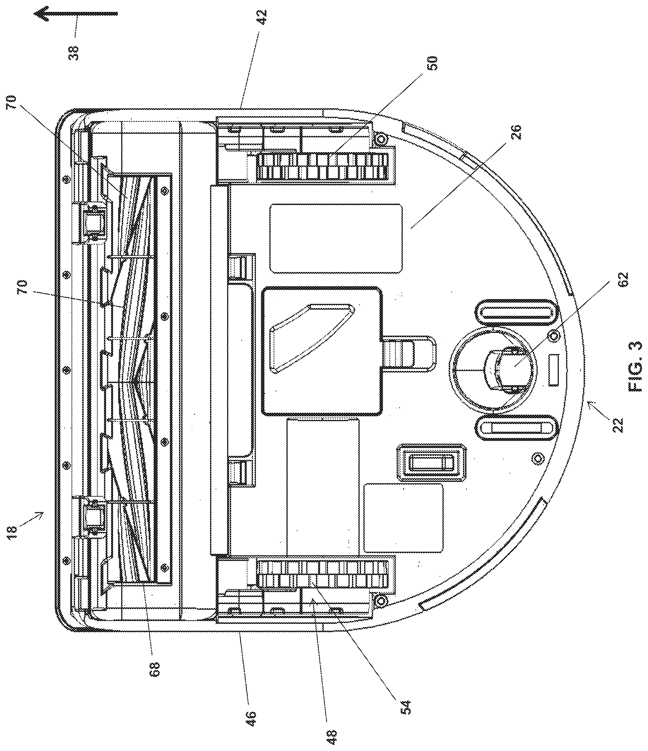
[0008] FIG. 3 is a plan view of the bottom of the autonomous cleaner of FIG. 2.
[0009] FIG. 4 is a front perspective view of the autonomous cleaner of FIG. 2 with a portion of an outer housing removed to illustrate a nozzle, a conduit, and a portion of a separator assembly.
[0010] FIG. 5 is a perspective view of the rear of the autonomous cleaner of FIG. 2.
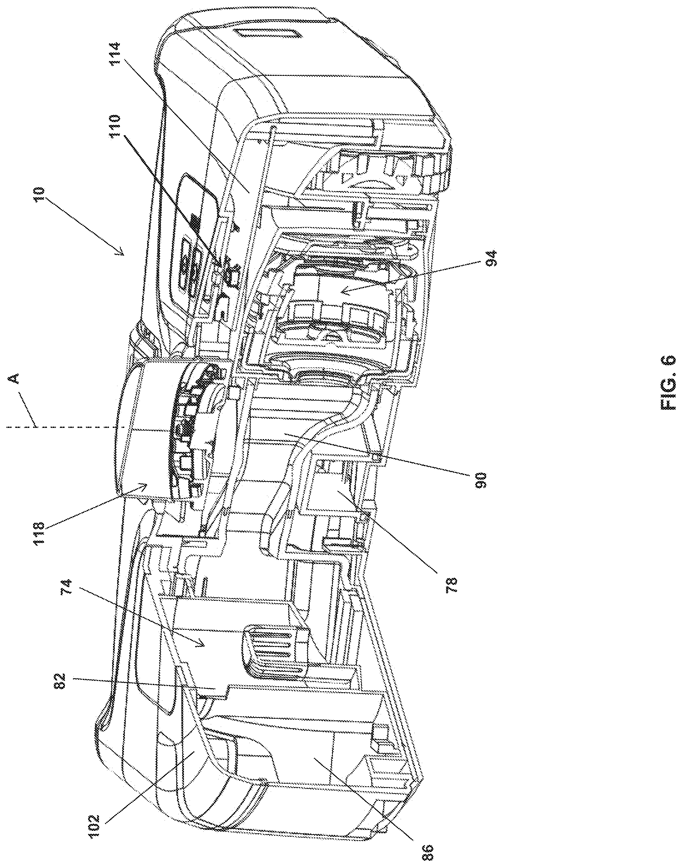
[0011] FIG. 6 is a perspective view of the autonomous cleaner of FIG. 5 with a portion of the outer housing removed to illustrate a portion of the separator assembly, a dust cup, and a suction motor assembly.
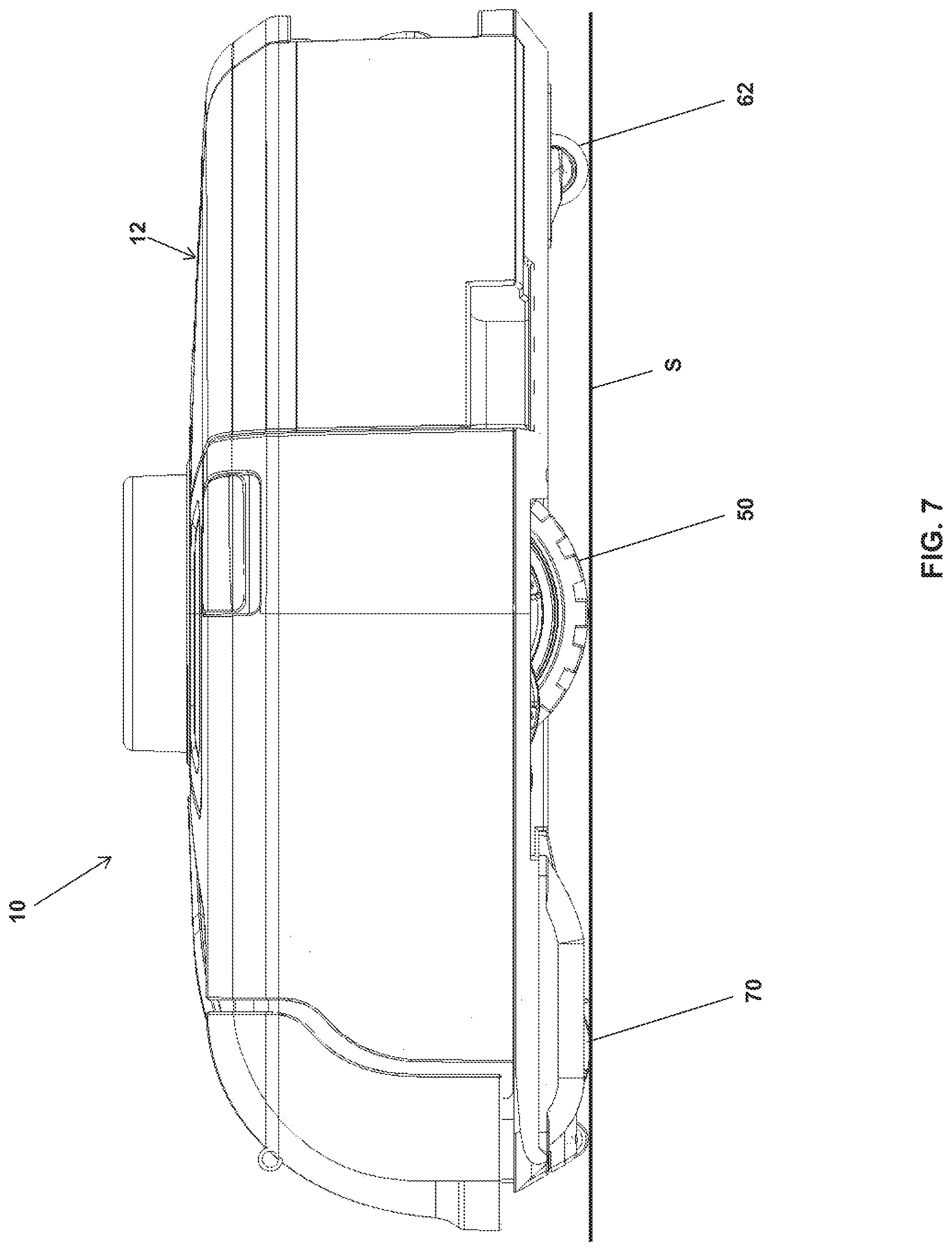
[0012] FIG. 7 is a right side elevational view of the autonomous cleaner of FIG. 2.
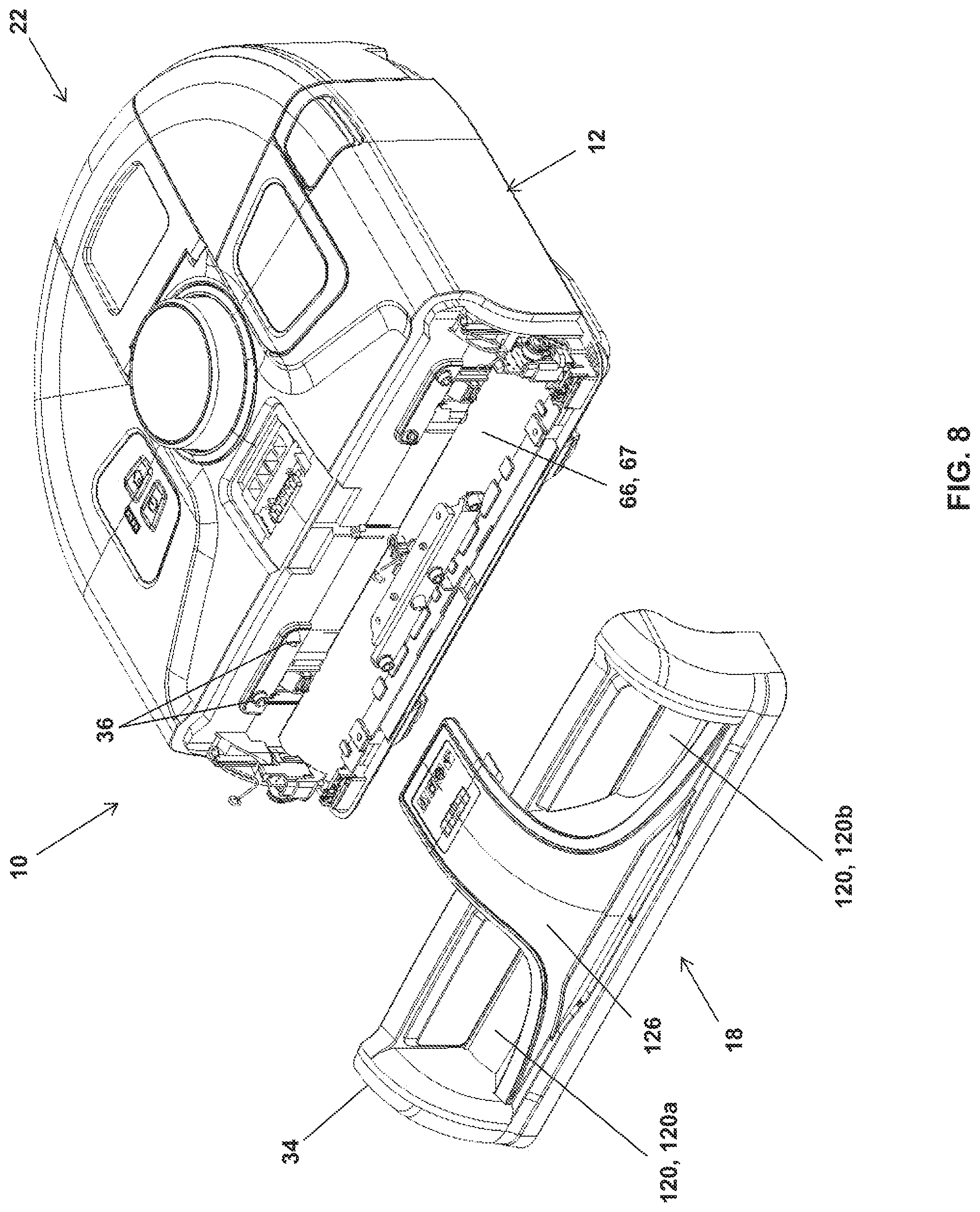
[0013] FIG. 8 is a partially exploded perspective view of the autonomous cleaner of FIG. 2.
[0014] FIG. 9 is a front perspective view of the bumper of the autonomous of FIG. 2.
[0015] FIG. 10 is a partially exploded perspective view of the bumper of FIG. 9.
[0016] FIG. 11 is a rear bottom perspective view of the bumper of FIG. 9.
DETAILED DESCRIPTION
[0017] Before any embodiments are explained in detail, it is to be understood that the present disclosure is not limited in its application to the details of construction and the arrangement of components set forth in the following description or illustrated in the following drawings. The present disclosure is capable of other embodiments and of being practiced or of being carried out in various ways. It should be understood that the description of specific embodiments is not intended to limit the disclosure from covering all modifications, equivalents and alternatives falling within the spirit and scope of the disclosure as defined in the appended claims. Also, it is to be understood that the phraseology and terminology used herein is for the purpose of description and should not be regarded as limiting.
[0018] Referring now to the figures, FIG. 1 illustrates an embodiment of an autonomous cleaner 10 having a bumper with a viewing window (as described below). The autonomous cleaner 10 can selectively engage a charging base 14. The charging base 14 (or base station 14 or charging station 14) can be coupled to a source of electricity (e.g., to a wall outlet by a cord, etc.). In response to the autonomous cleaner 10 engaging the charging base 14, the charging base 14 can supply electricity to the autonomous cleaner 10, and more specifically can supply electricity to recharge one or more batteries (not shown) that power the autonomous cleaner 10.
[0019] Referring to FIGS. 2-3, the autonomous cleaner 10 is shown disengaged from the charging base 14. The autonomous cleaner 10 includes a body 12 having a perimeter P and a front end 18 that is opposite a back end 22. The autonomous cleaner 10 also includes a chassis 26 (or an undercarriage 26 or a frame 26) (shown in FIG. 3). An outer housing 30 (or outer shell 30) cooperates with the chassis 26 to encase one or more components of the autonomous cleaner 10. The chassis 26 and the outer housing 30 may cooperate to define the body 12.
[0020] With specific reference to FIG. 2, a front bump sensor 34 (or bumper 34) is positioned at the front end 18 of the autonomous cleaner 10 and is mounted to and at least partially along the perimeter P of the body 12. The front bump sensor 34 is provided at a leading edge of the autonomous cleaner 10 in a direction of forward travel 38. The direction of forward travel 38 generally extends from the back end 22 towards the front end 18. The autonomous cleaner 10 is also configured to operate in a direction opposite the direction of forward travel 38, or in reverse.
[0021] Referring now to FIG. 3, the autonomous cleaner 10 includes a drive assembly 48. The drive assembly 48 includes a pair of motorized drive wheels 50, 54. A first drive wheel 50 is positioned proximate a first side 42, while a second drive wheel 54 is positioned proximate a second side 46 of the autonomous cleaner 10. The drive wheels 50, 54 can operate (or rotate) independently of each other. As such, the drive wheels 50, 54 can rotate at the same speed, resulting in the direction of forward travel 38 being generally straight, or can rotate at different speeds to facilitate a turning movement of the autonomous cleaner 10. The autonomous cleaner 10 can also include one or more third wheels 62, which can be driven or non-driven (e.g., a caster wheel 62).
[0022] The drive assembly 48 is operably connected to a controller 110 (shown in FIG. 6) of the autonomous cleaner 10. The controller 110 can be provided in association with a printed circuit board 114. The controller 110 may be configured to map the area to be cleaned and to operate the plurality of drive wheels 50, 54 to move the autonomous cleaner 10 (or the associated chassis 26) along a cleaning surface S (shown in FIG. 7) within the area to be cleaned.
[0023] For example, the controller 110 may be in communication with an area sensing unit that is configured to map the area to be cleaned. In the embodiment illustrated in FIGS. 4 and 6, the area sensing unit can be a laser distance sensor 118. The laser distance sensor 118 includes a laser emitter (not shown) and a light sensor (not shown). The laser emitter emits a beam (or a light beam or emitted light), and the light sensor detects light from the beam that is reflected by an obstacle (or reflected light). The light sensor outputs a signal to the controller 110 corresponding to a distance to the obstacle. In one example, the laser distance sensor 118 and the controller 110 are configured to calculate a distance to the obstacle by triangulation using the angle of reflected light and the distance between the laser emitter and the light sensor. In other embodiments, other laser rangefinders may be used. The laser distance sensor 118 measures a distance to objects at points around the autonomous cleaner 10 as the cleaner operates such that the controller 110 can determine the bounds of the map of the area to be cleaned as the autonomous cleaner 10 moves about the area.
[0024] In addition, the autonomous cleaner 10 can include one or more odometry encoders (not shown) operably connected to the drive wheels 50, 54, and configured to determine a distance and an estimated direction the autonomous cleaner 10 travels based on rotation of one or both of the drive wheels 50, 54. The odometry data from the encoders can be combined with the laser distance sensor data from the laser distance sensor 118 by the controller 110 using Simultaneous Localization and Mapping (SLAM) algorithms, or other mapping techniques, to develop the map of the area to be cleaned (or mapped area). The controller 110 can also control the autonomous cleaner 10 within the mapped area based on where the autonomous cleaner 10 travels.
[0025] In addition, the controller 110 may receive signals from one or more obstacle detection sensors to identify objects (or obstacles) in the area to be cleaned (e.g., a chair, a sofa, an ottoman, etc.). Obstacle detection sensors may include proximity sensors (e.g., infrared sensors, ultrasonic sensors, and tactile sensors), cliff sensors, bump sensors, or any other sensor that is configured to sense or detect an object as the autonomous cleaner travels. The controller 110 can then incorporate those objects into the map of the area to be cleaned. In the illustrated embodiment, the controller 110 may receive signals, for example, from the front bump sensor 34 to identify objects (or obstacles) in the area to be cleaned.
[0026] Referring back to FIGS. 2-4, the autonomous cleaner 10 includes a dust collection assembly 64 having a dust inlet 66. In the illustrated embodiment, the autonomous cleaner 10 is a vacuum cleaner and the dust inlet is a nozzle 66 (shown in FIG. 2). Optionally, the dust collection assembly 64 includes a brush roll 70 (shown in FIGS. 3-4) mounted adjacent the dust inlet or nozzle 66 that is configured to rotate at least partially within the dust inlet or nozzle 66 for engaging a portion of the cleaning surface S to facilitate dust collection. The nozzle 66 may be disposed interior of the perimeter P of the body 12 proximate a forward portion of the perimeter P of the body 12 and may be carried by the chassis 26. The brush roll 70 may extend through an air inlet 68, for example, an air inlet slot, of the nozzle 66 such that engagement of the brush roll 70 to a portion of the cleaning surface S cooperates with air flow into the air inlet slot 68 to facilitate dust collection. In an alternative embodiment, the autonomous cleaner may be a sweeper where the brush roll 70 extends through the dust inlet 66 such that engagement of the brush roll 70 to a portion of the cleaning surface S sweeps dust, dirt, or other debris into the dirt inlet to facilitate dust collection. To facilitate rotation, the brush roll 70 may be operably connected to a brush roll motor (not shown) by a belt (e.g., a geared belt, etc.) (not shown) and may be carried by the chassis 26. With specific reference to FIG. 4, the nozzle 66 is fluidly connected to a dust separator assembly 74 by a conduit 78 for transporting dirty air (i.e., air containing dust) drawn into the nozzle 66 at the air inlet 68 to the separator assembly 74. In the illustrated vacuum cleaner embodiment, the separator assembly 74 is a cyclonic separator. In other embodiments, the separator assembly 74 can be any suitable separator assembly (e.g., a bag unit, a filter unit, any suitable non-cyclone separator, etc.).
[0027] With continued reference to FIG. 4, dust that exits the separator assembly 74 through a dust outlet 82 collects in a dust cup 86 (or a dust collection chamber 86 or a dirt cup 86 or a collection bin 86) (shown in FIG. 6). In an alternative embodiment, the autonomous cleaner is a sweeper where the dust collection chamber 86 is proximate the dust inlet 66 and brush roll 70 and is configured for receiving dust swept by the brush roll. A portion of the outer housing 30 may form a removable cover (not shown) configured to cover the separator assembly 74 (or portion thereof) and the dust cup 86 (or portion thereof). With reference to FIG. 6, cleaned air exits through the separator assembly 74 by a clean air outlet 90, and travels to a suction motor assembly 94 and then is discharged through a vent 98 (shown in FIG. 5). More specifically, the suction motor assembly 94, which is in fluid communication with the nozzle 66 via the separator assembly 74, includes a suction motor 96 that rotates a fan or impeller to generate a suction airflow at the air inlet 68 for drawing dirty air through the suction nozzle 66 and into the separator assembly 74. The nozzle 66 has a transparent or translucent portion 67 that is formed proximate the brush roll 70. For example, the transparent or translucent portion 67 may be formed above the brush roll 70 (relative to the cleaning surface S) and may extend along a portion or the entire length of the nozzle 66.
[0028] Referring to FIGS. 5 and 8-9, an energy storage system 106 (or a battery pack 106) is positioned in the autonomous cleaner 10 to store and provide electricity to operate the autonomous cleaner 10, including various components and associated electronic circuits thereof, such as the drive assembly 48, the suction motor 96, the controller 110 and the laser distance sensor 118. The energy storage system 106 can include a plurality of cells or battery cells (not shown). The illustrated energy storage system 106 can be recharged (e.g., in a remote charging station, at the charging base 14, etc.).
[0029] With reference to FIGS. 8-11, the bumper 34 may include one or more viewing windows 120 for viewing the brush roll 70 (shown in FIGS. 3-4) mounted at the air inlet 68 (shown in FIGS. 3-4) of the nozzle 66. In the illustrated embodiment, the bumper 34 includes an opaque central portion 126 and a pair of viewing windows 120a and 120b formed in the bumper 34 on opposite sides of the opaque central portion 126. More specifically, the bumper 34 may include a frame member 124 having opposing first and second side walls 130 and 132, a neck body 134 located between the first and second side walls 130 and 132, a first rear wall 136 extending from the neck body 134 toward the first side wall 130, and a second rear wall 138 extending from the neck body 134 toward the second side wall 132. Alternatively, the frame member includes a rear wall extending between the opposing first and second side walls 130, 132. Optionally, a first arcuate arm 140 extends forwardly relative to the first rear wall 136 and outwardly from the neck body 134 to the first side wall 130. Similarly, a second arcuate arm 142 extends forwardly relative to the second rear wall 138 and outwardly from the neck body 134 to the second side wall 132. The first viewing window 120a may be provided in the frame member 124 forwardly of the first rear wall 136 and the second viewing window 120b is provided in the frame member 124 forwardly of the second rear wall 138. In the illustrated embodiment, the first viewing window 120a is formed as a first aperture or window between the first arcuate arm 140 and the first rear wall 136 and the second viewing window 120b is formed as a second aperture or window between the second arcuate arm 142 and the second rear wall 138, the apertures or windows corresponding to the transparent or translucent portion 67.
[0030] The frame member 124 may be an assembly of components, as shown in the illustrated embodiment, or may be a single piece, including for example an injection molded or other unitary, one-piece, integral construction. Also, in other embodiments, the viewing windows 120 of the bumper 34 may be formed from a transparent or translucent material, thereby allowing at least some visible light to pass through the material so that the nozzle 66 behind the bumper 34 (and the brush roll 70, as described below) is visible. In addition, although the illustrated embodiment illustrates a pair of viewing windows 120, it should be appreciated that other embodiments may include a bumper having a single viewing window, for example, a single viewing window that extends uninterrupted along the entire length of the bumper, or a bumper having three or more viewing windows, which may, for example, be formed between a plurality of opaque portions of the bumper.
[0031] With reference again to FIGS. 8-11, the transparent or translucent portion 67 of the dust inlet or nozzle 66 is received in a chamber 144 defined by the bumper 34. The viewing windows 120 of the bumper 34 are disposed adjacent the transparent or translucent portion 67 of the nozzle 66 such that a user can view the brush roll 70 through the viewing windows 120 and the transparent portion 67 of the nozzle 66. In the illustrated embodiment, for example, the viewing windows 120 are disposed above the transparent or translucent portion 67 of the nozzle 66 (relative to the cleaning surface S). The viewing windows 120 of the bumper 34 advantageously permit a user to visually detect whether an object is lodged in the nozzle 66 or the brush roll 70 fails to rotate properly during operation of the autonomous cleaner 10.
[0032] In addition, the first rear wall 136 of the bumper 34 may define one or more pass-through openings 146 that extend through the first rear wall 136. Each pass-through opening 146 may be aligned with an obstacle detection sensor 36, such as an infrared sensor or an ultrasonic sensor, that is mounted to the body 12 at the front end 18 of the autonomous cleaner 10 and is operable in combination with the controller 110 to remotely sense a surrounding environment, for example to identify objects (or obstacles) in the area to be cleaned. The pass-through openings 146 may be covered by sensor covers 148 to protect the obstacle detection sensors 36 from dust or dirt buildup or other damage without interfering with the operation of the sensors.
[0033] Thus, the present disclosure provides, among other things, a bumper with a viewing window for use with an autonomous cleaner. Various features and advantages of the present disclosure are set forth in the following claims.
* * * * *
D00000
D00001
D00002
D00003
D00004
D00005
D00006
D00007
D00008
D00009
D00010
D00011
XML
uspto.report is an independent third-party trademark research tool that is not affiliated, endorsed, or sponsored by the United States Patent and Trademark Office (USPTO) or any other governmental organization. The information provided by uspto.report is based on publicly available data at the time of writing and is intended for informational purposes only.
While we strive to provide accurate and up-to-date information, we do not guarantee the accuracy, completeness, reliability, or suitability of the information displayed on this site. The use of this site is at your own risk. Any reliance you place on such information is therefore strictly at your own risk.
All official trademark data, including owner information, should be verified by visiting the official USPTO website at www.uspto.gov. This site is not intended to replace professional legal advice and should not be used as a substitute for consulting with a legal professional who is knowledgeable about trademark law.