System And Method Of Locating Oscillation Sources Of Wind Power Integrated System Based On Energy Spectrums
Ma; Jing ; et al.
U.S. patent application number 16/891943 was filed with the patent office on 2021-02-04 for system and method of locating oscillation sources of wind power integrated system based on energy spectrums. The applicant listed for this patent is North China Electric Power University. Invention is credited to Yuanpei Gu, Jing Ma, Yaqi Shen, Dong Zhao.
| Application Number | 20210036518 16/891943 |
| Document ID | / |
| Family ID | 1000004884474 |
| Filed Date | 2021-02-04 |


View All Diagrams
| United States Patent Application | 20210036518 |
| Kind Code | A1 |
| Ma; Jing ; et al. | February 4, 2021 |
SYSTEM AND METHOD OF LOCATING OSCILLATION SOURCES OF WIND POWER INTEGRATED SYSTEM BASED ON ENERGY SPECTRUMS
Abstract
The present application proposes a method of locating oscillation sources of wind power integrated system based on energy spectrums. The method include: collecting information of voltage and current at the terminal of each generator and obtaining a dynamic energy curve of each generator over time; choosing the generators whose curve shows an upward trend in the dynamic energy over time curve into alternative generators; obtaining and processing energy spectrums of synchronous generator, DFIG with PLL, and/or an analogical energy spectrum of DFIG with virtual inertia among the alternative generators; selecting generator with maximum proportion of dominant oscillation mode as an oscillation source reference generator; and Calculating the similarity coefficients between energy spectrums of each remaining candidate generator and the oscillation source reference generator, determining the oscillation source generators.
| Inventors: | Ma; Jing; (Beijing, CN) ; Zhao; Dong; (Beijing, CN) ; Gu; Yuanpei; (Beijing, CN) ; Shen; Yaqi; (Beijing, CN) | ||||||||||
| Applicant: |
|
||||||||||
|---|---|---|---|---|---|---|---|---|---|---|---|
| Family ID: | 1000004884474 | ||||||||||
| Appl. No.: | 16/891943 | ||||||||||
| Filed: | June 3, 2020 |
| Current U.S. Class: | 1/1 |
| Current CPC Class: | H03L 7/099 20130101; H03L 7/18 20130101; H02J 3/24 20130101; H02J 3/381 20130101; G01R 31/086 20130101 |
| International Class: | H02J 3/38 20060101 H02J003/38; H02J 3/24 20060101 H02J003/24; H03L 7/18 20060101 H03L007/18; H03L 7/099 20060101 H03L007/099; G01R 31/08 20060101 G01R031/08 |
Foreign Application Data
| Date | Code | Application Number |
|---|---|---|
| Jul 30, 2019 | CN | 201910694996.3 |
Claims
1. A method of locating the oscillation sources of wind power integrated system based on energy spectrums, comprising the following steps: step 1: collecting the information of voltage and current at an output terminal of each generator in the system, and obtaining a dynamic energy curve of each generator over time; step 2: choosing generators whose curves show an upward trend in the dynamic energy curve over time into alternative generators; step 3: obtaining energy spectrums of synchronous generator, with a phase-locked loop, and/or an analogical Doubly-fed induction generator (DFIG) energy spectrum of DFIG with virtual inertia among the alternative generators; step 4: standardizing the amplitudes of the energy spectrums and/or the analogical energy spectrum, wherein a generator with maximum proportion of dominant oscillation mode is selected as an oscillation source reference generator; and step 5: calculating the similarity coefficients between energy spectrums of each remaining alternative generator and the oscillation source reference generator in the .+-.0.3 Hz frequency band of the dominant oscillation mode of the oscillation source reference generator; determining the oscillation source generators based on the similarity coefficients.
2. The method of locating the oscillation sources according to claim 1, wherein in the step 1, calculating dynamic energy of each generator by the following formula in order to obtain the dynamic energy curve of each generator over time: W=.intg.Im((-I.sub.G*)dU)=.intg.-P.sub.ed.delta.-.intg.I.sub.d{dot over (U)}.sub.q+.intg.I.sub.q{dot over (U)}.sub.d, where P.sub.e is the active power output by the each generator; .delta. is the angular difference between xy coordinate system and dq coordinate system; .delta. represents the power angle of a generator, when the generator is a synchronous generator; .delta. represents the phase-locked angle of PLL, when the generator is a Doubly-fed induction generator (DFIG) with PLL; .delta. presents the phase-locked angle of PLL, when the generator is a DFIG with virtual inertia; U.sub.d, U.sub.q, I.sub.d and I.sub.q are respectively the d-axis and q-axis components of the voltage and current output by the terminal of each generator.
3. The method of locating the oscillation sources according to claim 1, wherein the step 3 comprises: through Fourier decomposition for the dynamic energy of each generator in the time domain, obtaining the energy amplitude A(k) corresponding to the frequency component f(k), where k=1, 2, 3, 4, . . . , N/2, and N is a length of a discrete signal; the A(k) is the amplitudes of energy spectrums of the synchronous generator and DFIG with PLL; and the analogical energy spectrum of the DFIG with virtual inertia is A(k)/f.sup.2(k).
4. The method of locating the oscillation sources according to claim 3, wherein it also comprises: after normalizing the amplitudes of the energy spectrums and/or the analogical energy spectrum, standardizing the amplitudes of the energy spectrums and/or the analogical energy spectrum; wherein the calculation formula of the normalization process is: S ' ( k ) = S ( k ) - S _ ( k ) i = 1 N / 2 2 N [ S i ( k ) - S _ ( k ) ] 2 ##EQU00025## where S(k) is the amplitude of energy spectrum corresponding to each frequency; the amplitudes of energy spectrums of the synchronous generator and the DFIG with PLL are S(k)-A(k); the amplitude of analogical energy spectrum of the DFIG with virtual inertia is S(k)-A(k)/f.sup.2(k); S(k) is the average value of the amplitudes of energy spectrums; N is the number of frequencies; and S'(k) is the normalized amplitudes of energy spectrums.
5. The method of locating the oscillation sources according to claim 4, wherein in the step 4, standardizing all the normalized amplitudes of energy spectrums and/or the amplitude of the analogical energy spectrum in the 0.1 Hz-2.5 Hz, obtaining the ratio of the amplitudes of the energy spectrums of each oscillation modal and/or the amplitudes of analogical energy spectrum of each generator to the sum of the amplitudes of all the energy spectrums of the corresponding generators; wherein the generator with the largest proportion is the oscillation source reference generator.
6. The method of locating the oscillation sources according to claim 1, wherein in the step 5, according to the following formula calculating the similarity coefficients between energy spectrums of each remaining alternative generator and the oscillation source reference generator: r ( X , Y ) = n .SIGMA. xy - .SIGMA. x .SIGMA. y n .SIGMA. x 2 - ( .SIGMA. x ) 2 n .SIGMA. y 2 - ( .SIGMA. y ) 2 ##EQU00026## where x, y are respectively the energy spectrum data of the two generators under the dominant oscillation mode .+-.0.3 Hz; r is the calculated similarity coefficient.
7. The method of locating the oscillation sources according to claim 1, wherein in the step 5, when the similarity coefficient between energy spectrums of a generator and the oscillation source reference generator is greater than or equal to 0.7.+-.0.05, the generator is determined as the oscillation source generator.
8. A system of locating the oscillation source of wind power integrated system based on energy spectrums, comprising: sensors, a first processor, a second processor and a result output terminal; the sensors collect information of voltage and current at an output terminal of each generator in the system and transfer them to the first processor; the first processor receives the data transmitted by the sensors, and calculates a dynamic energy trend of each generator over time and transfers it to the second processor; the second processor receives the dynamic energy data of the output terminal of each generator, calculates the energy spectrums and locates the system oscillation source by comparing the similarity between the energy spectrums of each generator and the oscillation source reference generator; and the result output terminal is used for outputting a dominant oscillation mode and corresponding system oscillation source generators.
9. The system of locating the oscillation sources according to claim 8, wherein the first processor uses the following formula to calculate the dynamic energy change curve of each generator over time: W=.intg.Im((-I.sub.G*)dU)=.intg.-P.sub.ed.delta.-.intg.I.sub.d{dot over (U)}.sub.q+.intg.I.sub.q{dot over (U)}.sub.d, where P.sub.e is the active power output by the each generator; .delta. is the angular difference between xy coordinate system and dq coordinate system; .delta. represents the power angle of the generator, when the generator is a synchronous generator; .delta. represents the phase-locked angle of PLL, when the generator is a Doubly-fed induction generator (DFIG) with PLL; .delta. presents the phase-locked angle of PLL, when the generator is a DFIG with virtual inertia; U.sub.d, U.sub.g, I.sub.d and I.sub.q are respectively the d-axis and q-axis components of the voltage and current by the output terminal of each generator.
10. The system of locating the oscillation sources according to claim 8, wherein the working process of the second processor is as follows: choosing the generators whose curve shows an upward trend in the dynamic energy curve over time into alternative generators; obtaining energy spectrums of synchronous generators, DFIG with a phase-locked loop, and/or an analogical energy spectrum of DFIG with virtual inertia among the alternative generators; standardizing the amplitudes of the energy spectrums and/or the analogical energy spectrum; the generator with the maximum proportion of dominant oscillation mode is selected as an oscillation source reference generator; calculating the similarity coefficients between energy spectrums of each remaining alternative generator and the oscillation source reference generator in the .+-.0.3 Hz frequency band of the dominant oscillation mode of the oscillation source reference generator; determining the oscillation source generators based on the similarity coefficients.
11. A non-transitory machine-readable storage medium comprising instructions that when executed cause a processor of a computing device to: collect information of voltage and current at an output terminal of each generator in the system; calculate a dynamic energy trend of each generator over time based on the information; calculate the energy spectrums, and locate the system oscillation source by comparing the similarity between the energy spectrums of each generator and the oscillation source reference generator; and output a dominant oscillation mode and corresponding system oscillation source generators.
Description
CROSS-REFERENCE TO RELATED APPLICATIONS
[0001] This application claims priority to Chinese Patent Application No. 201910694996.3, filed on Jul. 30, 2019, which is hereby incorporated by reference in its entirety.
TECHNICAL FIELD
[0002] The application relates to the technical field of wind power generation system, and particularly relates to a system and method of locating oscillation sources of wind power integrated system based on energy spectrums.
BACKGROUND
[0003] As an additional control link of DFIG (Doubly-fed induction generator), virtual inertia may improve the inertia and frequency response characteristics of a system to some extent. However, it also opens the channel for the interaction of power between DFIG and system when disturbance occurs, which strengthens the coupling effect between DFIG and power grid. The virtual inertia will lower damping level of wind power integrated system and cause the oscillation mode where DFIG participates to exhibit weak damping, thus the system may easily oscillate, diverge and go unstable after being disturbed. On the other hand, apart from the dominant oscillation mode, other oscillation modes with weak damping may also be excited during the system oscillation process, and the coupling between multiple oscillation modes will cause the frequency components in the system oscillation waveform to be more complicated, making it difficult to locate the dominant oscillation source generators accurately. Therefore, in order to guarantee the stable level of the disturbed wind power integrated system, accurately locating oscillation source generators in the dominant oscillation mode has become a key issue to be solved urgently.
[0004] At present, the location of low-frequency oscillation disturbance sources in power system has gradually become a hot topic for many experts and scholars at home and abroad. However, existing studies on the location of oscillation source are mainly focused on traditional power system, and none has been taken into account the coupling effect of multiple oscillation modes generated by disturbance of wind power integrated system with virtual inertia. Thus, they cannot distinguish between oscillation source generators in the dominant oscillation mode and non-dominant oscillation modes, and cannot accurately locate the oscillation sources of the system.
SUMMARY
[0005] Based on above analysis, the application aims to propose a system and method of locating the oscillation sources of wind power integrated system based on energy spectrums. It is used to solve the problem that it is difficult to accurately locate the oscillation source generators when the system is stimulated with multiple oscillation modes after being disturbed.
[0006] The object of the present application is mainly realized by the following technical scheme:
[0007] On the one hand, a method of locating the oscillation sources of wind power integrated system based on energy spectrums is proposed, which includes the following steps:
[0008] step 1: collecting the information of voltage and current at an output terminal of each generator in the system, and obtain a dynamic energy curve of each generator over time;
[0009] step 2: choosing generators whose curves show an upward trend in the dynamic energy curve over time into alternative generators;
[0010] step 3: obtaining energy spectrums of synchronous generator, DFIG with a phase-locked loop, and/or analogical energy spectrum of DFIG with virtual inertia among the alternative generators;
[0011] step 4: standardizing the amplitudes of the energy spectrums and/or the analogical energy spectrum, wherein generator with maximum proportion of dominant oscillation mode is selected as an oscillation source reference generator; and
[0012] step 5: calculating the similarity coefficients between energy spectrums of each remaining alternative generator and the oscillation source reference generator in the .+-.0.3 Hz frequency band of the dominant oscillation mode of the oscillation source reference generator; determining the oscillation source generators based on the similarity coefficients.
[0013] Further, in the step 1, calculating the dynamic energy of each generator by the following formula in order to obtain the dynamic energy curve of each generator over time:
W=.intg.Im((-I.sub.G*)dU)=.intg.-P.sub.ed.delta.-.intg.I.sub.d{dot over (U)}.sub.q+.intg.I.sub.q{dot over (U)}.sub.d,
[0014] Where P.sub.e is the active power output by the each generator; .delta. is the angular difference between xy coordinate system and dq coordinate system; .delta. represents the power angle of a generator, when the generator is a synchronous generator; .delta. represents the phase-locked angle .delta..sub.pll of PLL, when the generator is a DFIG with PLL (Phase-locked loop); .delta. presents the phase-locked angle .delta..sub.pll of PLL, when the generator is a DFIG with virtual inertia; U.sub.d, U.sub.q, I.sub.d and I.sub.q are respectively the d-axis and q-axis components of the voltage and current output by the terminal of each generator.
[0015] Further, the step 3 includes: through Fourier decomposition for the dynamic energy of each generator in the time domain, obtaining the energy amplitude A(k) corresponding to the frequency component f(k), where k=1, 2, 3, 4, . . . , N/2, and N is a length of a discrete signal;
[0016] the A(k) is the amplitudes of energy spectrums for the synchronous generator and the DFIG with PLL;
[0017] the analogical energy spectrum for the DFIG with virtual inertia is A(k)/f.sup.2 (k).
[0018] Further, which also includes: after normalizing the amplitudes of the energy spectrums and/or the analogical energy spectrum, standardizing the amplitudes of the energy spectrums and/or the analogical energy spectrum; wherein the calculation formula of the normalization process is:
S ' ( k ) = S ( k ) - S _ ( k ) i = 1 N / 2 2 N [ S i ( k ) - S _ ( k ) ] 2 ##EQU00001##
[0019] where S(k) is the amplitude of energy spectrum corresponding to each frequency; the amplitudes of energy spectrums of the synchronous generators and the DFIG with PLL are S(k)=A(k); the amplitude of analogical energy spectrum of the DFIG with virtual inertia is S(k)=A(k)/f.sup.2(k); S(k) is the average value of the amplitudes of energy spectrums; N is the number of frequencies; S'(k) is the normalized amplitudes of energy spectrums.
[0020] Further, in the step 4, standardizing all the normalized amplitudes of energy spectrums and/or the amplitude of the analogical energy spectrum in the 0.1 Hz-2.5 Hz, which can obtain the ratio of the amplitudes of the energy spectrums of the oscillation modal and/or the amplitude of analogical energy spectrum of each generator to the sum of the amplitudes of all the energy spectrums of the corresponding generators; wherein a generator with the largest proportion is the oscillation source reference generator.
[0021] Further, in the step 5, according to the following formula to calculate the similarity coefficients between energy spectrums of each remaining alternative generator and the oscillation source reference generator:
r ( X , y ) = n .SIGMA. xy - .SIGMA. x .SIGMA. y n .SIGMA. x 2 - ( .SIGMA. x ) 2 n .SIGMA. y 2 - ( .SIGMA. y ) 2 ##EQU00002##
[0022] where x, y are the energy spectrum data of the two generators in the .+-.0.3 Hz frequency band of the dominant oscillation mode; r is the calculated similarity coefficient.
[0023] Further, in the step 5, when the similarity coefficient between energy spectrums of a generator and the oscillation source reference generator is greater than or equal to 0.7.+-.0.05, the generator is determined as the oscillation source generator.
[0024] On the other hand, a system of locating the oscillation sources of wind power integrated system based on energy spectrums is proposed, which includes sensors, a first processor, a second processor and a result output terminal;
[0025] the sensors collect information of voltage and current at the output terminal of each generator in the system and transfer it to the first processor;
[0026] the first processor receives the data transmitted by the sensors, and calculates a dynamic energy change trend of each generator over time and transfers it to the second processor;
[0027] the second processor receives the dynamic energy data of the output terminal of each generator, calculates the energy spectrums and locates the system oscillation sources by comparing the similarity between the energy spectrums of each generator and the oscillation source reference generator; and
[0028] the result output is used for outputting a dominant oscillation mode and corresponding system oscillation source generators.
[0029] Further, the first processor calculates the dynamic energy change curve of each generator over time by the following formula:
W=.intg.Im((-I.sub.G*)dU)=.intg.-P.sub.ed.delta.-.intg.I.sub.d{dot over (U)}.sub.q+.intg.I.sub.q{dot over (U)}.sub.d
[0030] Where P.sub.e is the active power output by the each generator; .delta. is the angular difference between xy coordinate system and dq coordinate system; .delta. represents the power angle of a generator, when the generator is a synchronous generator; .delta. represents the phase-locked angle .delta..sub.pll of PLL, when the generator is a DFIG with PLL; .delta. presents the phase-locked angle .delta..sub.pll of PLL, when the generator is a DFIG with virtual inertia; U.sub.d, U.sub.q, I.sub.d and I.sub.q are respectively the d-axis and q-axis components of the voltage and current at the output terminal of each generator.
[0031] Further, the working process of the second processor is as follows:
[0032] choosing the generators whose curves show upward trend in the dynamic energy curves over time into alternative generators;
[0033] obtaining energy spectrums of synchronous generator, DFIG with the phase-locked loop, and/or an analogical energy spectrum of DFIG with virtual inertia among the alternative generators;
[0034] standardizing the amplitudes of the energy spectrums and/or the analogical energy spectrum; wherein a generator with the maximum proportion of dominant oscillation mode is selected as an oscillation source reference generator;
[0035] calculating the similarity coefficients between energy spectrums of each remaining alternative generator and the oscillation source reference generator in the .+-.0.3 Hz frequency band of the dominant oscillation mode of the oscillation source reference generator; determining the oscillation source generators based on the similarity coefficients.
[0036] Compared with the present technologies, the application has at least one of the following beneficial effects:
[0037] 1) The proposed method of locating the oscillation sources of wind power integrated system based on energy spectrums can monitor in real time the dynamic energy change curve of each generator over time by measuring the voltage and current information at the terminal of each generator in the system, preliminary identify the alternative generators and realize online evaluation of system damping and online tracking of conduction path of oscillation components. By comparing the similarity of the dynamic energy spectrums of different terminals of generators in the vicinity of the oscillation mode, it can avoid the influence of non-dominant oscillation mode on the location of the oscillation sources, and realize the rapid and accurate identification of the dominant oscillation source generators under complex system conditions, which is helpful to isolate the fault generator in time, restrain the development and divergence of oscillation, and ensure the safe and stable operation of the system.
[0038] 2) In the proposed system of locating oscillation sources of wind power integrated system based on energy spectrums, the proposed second processor receives the dynamic energy data at the output port of each generator, calculates the energy spectrums and compares the similarity between the energy spectrums of each generator and the oscillation source reference generator, which can quickly and accurately identify the system oscillation sources, realize the online location of the oscillation sources, and provide a strong guarantee for the stable and safe operation of the system.
[0039] In the application, the above technical schemes can be combined with each other to realize more preferred combination schemes. Other features and advantages of the application will be described in a subsequent specification, and some of the advantages may become apparent from the specification or be understood by implementing the application. The object and other advantages of the application can be realized and obtained through the contents specially pointed out in the specification and the drawings.
BRIEF DESCRIPTION OF DRAWINGS
[0040] The attached figures are only for the purpose of illustrating specific embodiments, and are not considered to be a limitation of the application. In the whole figures, the same reference symbols represent the same parts.
[0041] FIG. 1 is a flow chart of a method of locating the oscillation sources of wind power integrated system based on energy spectrums in the embodiment.
[0042] FIG. 2 is a phase-locked loop model in the embodiment.
[0043] FIG. 3 is a block diagram of a typical virtual inertia control in the embodiment.
[0044] FIG. 4 is a model of DFIG integrated system in the embodiment.
[0045] FIG. 5 is the IEEE 10-machine 39-bus system in the embodiment.
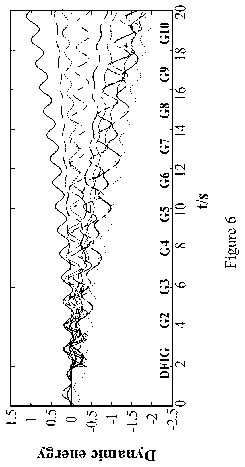
[0046] FIG. 6 is the variation curve of dynamic energy of each generator in the embodiment.
[0047] FIG. 7 is the energy spectrums of alternative generators in the embodiment.
[0048] FIG. 8 is the histogram of similarity among energy spectrums of different generators in the embodiment.
DESCRIPTION OF EMBODIMENTS
[0049] The preferred embodiments of the application will be described below in combination with the attached figures in detail, where the attached figures form part of the application and, together with the embodiments of the application, are used to explain the principles of the application, not to define the scope of the application.
[0050] The application proposes a method of locating the oscillation sources of wind power integrated system based on energy spectrums. This method is based on the theoretical support that the spectral characteristics of the oscillation source generators are that the amplitude of dominant oscillation mode is much larger than that of the non-dominant oscillation mode. In order to facilitate the understanding of the technical proposal of the application, the following theoretical analysis is used to elaborate in detail that the spectrum characteristics of the oscillation source generators are that the amplitude of the dominant oscillation mode is much larger than that of the non-dominant oscillation mode. The specific analysis process is as follows:
[0051] step S1: a dynamic energy model of DFIGs containing virtual inertia and phase locked loop (PLL) control modules is constructed.
[0052] The dynamic equations of PLL can be expressed as:
{dot over (x)}.sub.PLL=-u.sub.sd
{dot over (.delta.)}.sub.PLL=.omega..sub.s_PLL-.omega..sub.n
.omega..sub.s_PLL=K.sub.I_PLLx.sub.PLL-K.sub.P_PLLu.sub.sd,
[0053] Where x.sub.pll is an intermediate variable introduced, u.sub.sd is DFIG stator d-axis voltage, .delta..sub.PLL represents the angle of the observed stator voltage vector leading the x-axis in the xy coordinate, .omega..sub.s_PLL is the rotating angular speed of dq coordinate system measured by PLL, .omega..sub.n is the grid frequency, K.sub.I and K.sub.P are PLL PI controller parameters, as shown in FIG. 2.
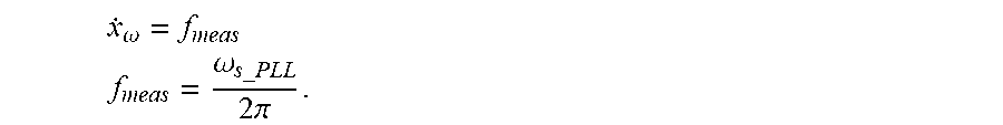
[0054] The virtual inertia control model can be expressed as:
x . .omega. = f meas ##EQU00003## f meas = .omega. s _ PLL 2 .pi. . ##EQU00003.2##
[0055] Where x.sub..omega. is the intermediate variable introduced, f.sub.meas is the value of system frequency measured by PLL, which is
f meas = .omega. s _ PLL 2 .pi. . ##EQU00004##
[0056] According to the deviation of system frequency, the variation of active power released by virtual inertia control .DELTA.P.sub.VI can be expressed as:
.DELTA. P VI = - K .omega. d .DELTA. f dt = - K .omega. 2 .pi. d 2 .DELTA..delta. pll dt 2 . ##EQU00005##
[0057] Where K.sub..omega. is the proportion parameter of virtual inertia control, and K.sub..omega.>0.
[0058] After virtual inertia control is introduced, the reference value of active power of rotor-side converter P.sub.ref will be adjusted according to the variation in system frequency. The variation of DFIG stator-side active power caused by virtual inertia .DELTA.P.sub.s is:
.DELTA. P s = .DELTA. P ref = .DELTA. P VI = - K .omega. 2 .pi. d 2 .DELTA..delta. pll dt 2 . ##EQU00006##
[0059] The energy function of the system can be constructed based on the node current equation. The energy of the system can be obtained by integrating node voltage U.sub.B, generator injection current I.sub.G and load current I.sub.L along system trajectory:
W=.intg.I.sub.m(((YU.sub.B-I.sub.G+I.sub.L)*).sup.TdU.sub.B) (1)
[0060] Where Y is admittance matrix of the system, U.sub.B is the column vector of bus voltage. I.sub.G and I.sub.L are respectively the column vectors of generator node injection current and load node injection current. I.sub.m represents extracting the imaginary part of a complex.
[0061] Take the energy of the generator from the energy of the system, and apply dq transformation for the node voltage and node current, and then combine the generator rotor motion equation, to obtain the expression of DFIG terminal dynamic energy:
W=.intg.Im((-I.sub.G*)dU)=.intg.-P.sub.ed.delta.-.intg.I.sub.d{dot over (U)}.sub.q+.intg.I.sub.q{dot over (U)}.sub.d (2).
[0062] Where P.sub.e is the active power output by the each generator; .delta. is the angular difference between xy coordinate system and dq coordinate system; .delta. represents the power angle of a generator, when the generator is a synchronous generator; .delta. represents the phase-locked angle .delta..sub.pll of PLL, when the generator is a DFIG with PLL; .delta. presents the phase-locked angle .delta..sub.pll of PLL, when the generator is a DFIG with virtual inertia; U.sub.d, U.sub.q, I.sub.d and I.sub.q are respectively the d-axis and q-axis components of the voltage and current output by the terminal of each generator.
[0063] Considering that electrical variables measured directly contain steady-state components irrelevant to oscillation, the dynamic energy obtained by equation (1) cannot accurately reflect the accumulation process of energy during oscillation. To filter out the effect of steady-state component of the energy, the variation values of electrical variables are used to calculate the dynamic energy generated during oscillation, i.e.
.DELTA.W=.intg.-.DELTA.P.sub.ed.DELTA..delta.-.intg..DELTA.I.sub.d.DELTA- .{dot over (U)}.sub.q+.intg..DELTA.I.sub.q.DELTA.{dot over (U)}.sub.d (3).
[0064] The dynamic energy of the terminal of each generator in the equation (3) can be divided into two parts:
.DELTA.W.sub.1=.intg..DELTA.P.sub.ed.DELTA..delta..sub.pll (4).
.DELTA.W.sub.2=-.intg..DELTA.I.sub.d.DELTA.{dot over (U)}.sub.q+.intg..DELTA.I.sub.q.DELTA.{dot over (U)}.sub.d (5).
[0065] Where .DELTA.W.sub.1 is the energy generated by PLL, and .DELTA.W.sub.2 is the energy generated by grid-side line.
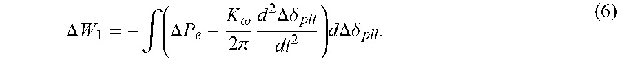
[0066] The virtual inertia uses frequency output by PLL as its input, and it provides support for system inertia by changing the active power output by the stator. Thus, virtual inertia mainly affects .DELTA.W.sub.1 in the equation (4). Substituting the active power change with virtual inertia into equation (4), the expression of .DELTA.W.sub.1 containing virtual inertia can be obtained:
.DELTA. W 1 = - .intg. ( .DELTA. P e - K .omega. 2 .pi. d 2 .DELTA..delta. pll dt 2 ) d .DELTA..delta. pll . ( 6 ) ##EQU00007##
[0067] .DELTA.W.sub.2 in the equation (5) is mainly determined by transmission line parameters. Suppose low frequency oscillation with frequency .omega..sub.d occurs in DFIG integrated system, and the amplitude of current oscillation component is I.sub.n, the d-axis and q-axis components of current at the grid-connecting point of DFIG can be expressed as:
.DELTA.i.sub.d=I.sub.n cos((.omega..sub.s-.omega..sub.d)t+.phi.)
.DELTA.i.sub.q=-I.sub.n sin((.omega..sub.s-.omega..sub.d)t+.phi.) (7).
[0068] The relationship between d-axis and q-axis components of voltage and current at the grid-connecting point is:
U d = L di d dt - .omega. Li q U q = L di q dt + .omega. Li d . ( 8 ) ##EQU00008##
[0069] Substituting the equation (7) and the equation (8) into the equation (5), so that:
.DELTA.W.sub.2=-1/2.omega.LI.sub.n.sup.2 (9)
[0070] According to equation (9), the dynamic energy generated by line is a constant value without any periodical component, and unaffected by the rising and falling trends of dynamic energy. Thus, the dynamic energy of DFIG is mainly affected by PLL and virtual inertia during low frequency oscillation.
[0071] Step S2: According to the dynamic energy expression of DFIG with virtual inertia obtained by equation (6), the energy spectrums of DFIGs with virtual inertia and PLL as an oscillation source and a non-oscillation source are derived, and their energy spectrum characteristics are analyzed. The specific process is as follows:
[0072] Step S201: to construct a DFIG integrated power system model.
[0073] For the DFIG integrated system, there are two oscillation modes for low frequency oscillation, namely local oscillation mode and inter-region oscillation mode. Both of oscillation modes can be represented by relative oscillations between the two generator groups. As a result, in the application, an equivalent three-generator system is taken as an example to perform theoretical derivation of the energy spectrums, system structure is shown in FIG. 4, where G3 is the reference generator group. After disturbance occurs in the system, the oscillation mode generated between G1 and G3 is .omega..sub.1, which is the dominant oscillation mode. G1 is the oscillation source generator group. The oscillation mode generated between G2 and G3 is .omega..sub.2, which is the non-dominant oscillation mode. G2 is non-oscillation source generator group. The oscillation component generated by the phase angle of voltage at bus 4 is .DELTA..theta..sub.4=a sin .omega..sub.1t+b sin .omega..sub.2t where a>b.
[0074] Step S202: to derive the energy spectrums of synchronous generator(s), DFIG(s) with PLL, and DFIG(s) with virtual inertia as oscillation sources and non-oscillation sources.
[0075] (1) The energy spectrum expression when the synchronous generator is used as an oscillation source is:
F 1 ( .omega. 1 ) F 1 ( .omega. 2 ) = ( C 1 + M 1 ) 2 + ( C 2 + N 1 ) 2 + a 4 ( C 1 + M 1 ) 2 + ( C 2 + N 1 ) 2 M 2 2 + N 2 2 + b 4 M 2 2 + N 2 2 [ C 1 2 + C 2 2 ] ( d 1 2 + b 1 2 ) + K D 1 a ( d 1 C 1 - b 1 C 2 ) + ( K D 1 a ) 2 + a 4 K D 1 b + b 4 [ C 1 2 + C 2 2 ] ( d 1 2 + b 1 2 ) + K D 1 a ( d 1 C 1 - b 1 C 2 ) + ( K D 1 a ) 2 K D 1 b . ##EQU00009##
[0076] Where C.sub.1, C.sub.2, M.sub.1, N.sub.1, M.sub.2 and N.sub.2 are the coefficients of different amplitude components of power angle oscillation of G1, the expressions of which are respectively:
{ C 1 = .DELTA..delta. 10 , C 2 = .DELTA..omega. 10 - .alpha..DELTA..delta. 10 .omega. 1 M 1 = - b 1 K N a b 1 2 + d 1 2 , N 1 = d 2 K N a b 1 2 + d 1 2 M 2 = - b 2 K N b b 2 2 + d 2 2 , N 2 = d 2 K N b b 2 2 + d 2 2 b 1 = K D 1 .omega. 1 , d 1 = K s 1 - M 1 .omega. 1 2 b 2 = K D 1 .omega. 2 , d 2 = K s 1 - M 1 .omega. 2 2 . ##EQU00010##
[0077] Where K.sub.D, K.sub.S and K.sub.N are respectively:
{ K D 1 = D 1 K s 1 = E 1 E 2 B 12 cos .delta. 10 + E 1 V 3 B 13 cos ( .delta. 10 - .theta. 40 ) K N 1 = E 1 V 3 B 13 cos ( .delta. 10 - .theta. 40 ) . ##EQU00011##
[0078] (2) The energy spectrum expression when the synchronous generator is used as a non-oscillation source is:
F 2 ( .omega. 1 ) F 2 ( .omega. 2 ) = G 1 2 + H 1 2 + a 4 G 1 2 + H 1 2 ( G 0 + G 2 ) 2 + ( H 0 + H 2 ) 2 + b 4 ( G 0 + G 2 ) 2 + ( H 0 + H 2 ) 2 = K D 2 a + a 4 [ G 0 2 + H 0 2 ] ( m 1 2 + n 1 2 ) + K D 2 b ( n 1 G 0 - m 1 H 0 ) + ( K D 2 b ) 2 + b 4 K D 2 a [ G 0 2 + H 0 2 ] ( m 1 2 + n 1 2 ) + K D 2 b ( n 1 G 0 - m 1 H 0 ) + ( K D 2 b ) 2 ##EQU00012##
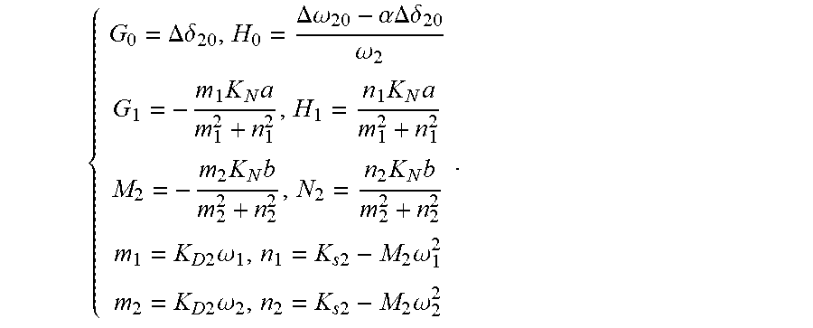
[0079] Where G.sub.0, H.sub.0, G.sub.1, H.sub.1, G.sub.2 and H.sub.2 are the coefficients of different amplitude components of power angle oscillation of G2 respectively, the expressions of which are respectively:
{ G 0 = .DELTA..delta. 20 , H 0 = .DELTA..omega. 20 - .alpha..DELTA..delta. 20 .omega. 2 G 1 = - m 1 K N a m 1 2 + n 1 2 , H 1 = n 1 K N a m 1 2 + n 1 2 M 2 = - m 2 K N b m 2 2 + n 2 2 , N 2 = n 2 K N b m 2 2 + n 2 2 m 1 = K D 2 .omega. 1 , n 1 = K s 2 - M 2 .omega. 1 2 m 2 = K D 2 .omega. 2 , n 2 = K s 2 - M 2 .omega. 2 2 . ##EQU00013##
[0080] Where K.sub.D2, K.sub.S1 and K.sub.N2 are respectively:
{ K D 2 = D 2 K s 2 = E 1 E 2 B 12 cos .delta. 20 + E 2 V 3 B 13 cos ( .delta. 20 - .theta. 40 ) K N 2 = E 2 V 3 B 23 cos ( .delta. 20 - .theta. 40 ) . ##EQU00014##
[0081] (3) The energy spectrum expression when DFIG with PLL is used as an oscillation source is:
F D ( .omega. 3 ) F D ( .omega. 2 ) = ( A 0 + A 1 ) 2 + ( B 0 + B 1 ) 2 + a 4 ( A 0 + A 1 ) 2 + ( B 0 + B 1 ) 2 A 2 2 + B 2 2 + b 4 A 2 2 + B 2 2 = [ A 0 2 + B 0 2 ] ( e 1 2 + f 1 2 ) + K p U s a ( f 1 A 0 - e 1 B 0 ) + ( K p U s a ) 2 + a 4 K p U s b + b 4 [ A 0 2 + B 0 2 ] ( e 1 2 + f 1 2 ) + K p U s a ( f 1 A 0 - e 1 B 0 ) + ( K p U s a ) 2 K p U s b . ##EQU00015##
[0082] Where the expressions of A.sub.0, B.sub.0, A.sub.1, B.sub.1, A.sub.2 and B.sub.2 are respectively:
{ A 0 = .DELTA..delta. pll 0 , B 0 = .DELTA..omega. pll 0 - .alpha..DELTA..delta. pll 0 .omega. 1 A 1 = - e 1 K t U s a e 1 2 + f 1 2 , B 1 = f 1 K t U s a e 1 2 + f 1 2 A 2 = - e 2 K t U s b e 2 2 + f 2 2 , B 2 = f 2 K t U s b e 2 2 + f 2 2 e 1 = K p U s .omega. 3 , f 1 = K t U s - .omega. 3 2 e 2 = K p U s .omega. 2 , f 2 = K t U s - .omega. 2 2 . ##EQU00016##
[0083] (4) The energy spectrum expression when DFIG with virtual inertia is used as an oscillation source is:
F D ( .omega. 3 ) F D ( .omega. 2 ) = ( A 0 + A 1 ) 2 + ( B 0 + B 1 ) 2 + a 4 ( A 0 + A 1 ) 2 + ( B 0 + B 1 ) 2 A 2 2 + B 2 2 + b 4 A 2 2 + B 2 2 = [ A 0 2 + B 0 2 ] ( e 1 2 + f 1 2 ) + K p U s a ( f 1 A 0 - e 1 B 0 ) + ( K p U s a ) 2 + a 4 K p U s b + b 4 [ A 0 2 + B 0 2 ] ( e 1 2 + f 1 2 ) + K p U s a ( f 1 A 0 - e 1 B 0 ) + ( K p U s a ) 2 K p U s b . ##EQU00017##
[0084] Step S203: to analyze the energy spectrum characteristics of the synchronous generator(s), the DFIG(s) with PLL, and the DFIG(s) with virtual inertia as oscillation sources and non-oscillation sources.
[0085] In the energy spectrums of the synchronous generator, since d.sub.1.sup.2+b.sub.1.sup.2 is proportional to .omega..sub.1.sup.2, and the magnitude of d.sub.1.sup.2+b.sub.1.sup.2 is larger, but the magnitude of K.sub.D1 is smaller, thus [C.sub.1.sup.2+C.sub.2.sup.2](d.sub.1.sup.2+b.sub.1.sup.2)+K.sub.D1a(d.su- b.1C.sub.1-b.sub.1C.sub.2)>>0 and the spectrum of the oscillation source generator of G1 satisfies:
F 1 ( .omega. 1 ) F 1 ( .omega. 2 ) >> a 2 b 2 , ##EQU00018##
i.e. the energy amplitude of dominant frequency component is much larger than the energy amplitude of non-dominant frequency component.
[0086] The energy spectrum of the non-oscillation source of the synchronous generator satisfies:
F 1 ( .omega. 1 ) F 1 ( .omega. 2 ) << a 2 b 2 , ##EQU00019##
i.e. the energy amplitude of dominant frequency component may be close to or smaller than the energy amplitude of non-dominant frequency component.
[0087] When the DFIG with PLL is used as an oscillation source, its energy spectrum is similar as the energy spectrum of the synchronous generator as the oscillation source, i.e. its energy amplitude of dominant frequency component is much larger than the energy amplitude of the other frequency components. When the DFIG is used as a non-oscillation source, its energy spectrum is similar to the energy spectrum of non-oscillation source of the synchronous generator, and significantly different from the energy spectrum of oscillation source generators.
[0088] The introduction of the virtual inertia will change the energy spectrum of DFIG, i.e. adding frequency coefficient
.omega. 3 2 .omega. 2 2 ##EQU00020##
to the amplitude of each energy component, thus the energy amplitudes of dominant oscillation mode and non-dominant oscillation mode cannot be estimated directly. Thus, an analogical energy spectrum is constructed in the application to eliminate the effect of frequency coefficient introduced by the virtual inertia. The analogical energy spectrum of DFIG
F VI ( .omega. 3 ) / f 3 2 F VI ( .omega. 2 ) / f 2 2 ##EQU00021##
can be obtained:
F VI ( .omega. 3 ) / f 3 2 F VI ( .omega. 2 ) / f 2 2 = F D ( .omega. 3 ) F D ( .omega. 2 ) = [ A 0 2 + B 0 2 ] ( e 1 2 + f 1 2 ) + K p U s a ( f 1 A 0 - e 1 B 0 ) + ( K p U s a ) 2 + a 4 K p U s b + b 4 [ A 0 2 + B 0 2 ] ( e 1 2 + f 1 2 ) + K p U s a ( f 1 A 0 - e 1 B 0 ) + ( K p U s a ) 2 K p U s b . ##EQU00022##
[0089] The analogical energy spectrum of DFIG with virtual inertia has the same characteristics as the energy spectrum of DFIG with PLL. Therefore, there is significant difference between the analogical energy spectrums of oscillation source and non-oscillation source of the DFIGs with PLL and virtual inertia.
[0090] According to the above energy spectrum analysis, the energy spectrum characteristics of the oscillation source generators are: the energy amplitude of the dominant oscillation mode is much larger than the energy amplitude of the non-dominant oscillation mode. The energy spectrum characteristics of the non-oscillation source generator are: the energy amplitude of the dominant oscillation mode is close to or even smaller the energy amplitude of the non-dominant oscillation mode.
The First Embodiment
[0091] Based on the theoretical analysis, a method of locating oscillation sources of wind power integrated system based on energy spectrums in this embodiment is proposed, as shown in FIG. 1. It specifically includes the following steps:
[0092] Step 1: collecting the information of voltage U and current I.sub.G at the output terminal of each generator in the system and substituting them into equation (2) in order to obtain a dynamic energy curve of each generator over time.
[0093] Step 2: choosing the generators whose curve shows an upward trend in the dynamic energy curve over time into alternative generators, i.e. the negative damping generators are classified as the alternative generators.
[0094] Step 3: obtaining energy spectrums of synchronous generators, DFIGs with a phase-locked loop, and/or an analogical energy spectrum of DFIGs with virtual inertia among the alternative generators.
[0095] Through Fourier decomposition for the dynamic energy of each generator in the time domain, the energy amplitude A(k) corresponding to the frequency component f(k) can be obtained, where k=1, 2, 3, 4, . . . , N/2, and N is a length of the discrete signal; A(k) is the amplitudes of energy spectrums for the synchronous generator and DFIG with PLL; the analogical energy spectrum for the DFIG with virtual inertia is A(k)/f.sup.2 (k).
[0096] The existence of the singular data in the amplitude of energy spectrum will affect the accuracy of similarity analysis results. So, in order to eliminate the effect of noise in the data, the following formula is used to normalize the amplitudes of the energy spectrums and/or the amplitude of the analogical energy spectrum:
S ' ( k ) = S ( k ) - S _ ( k ) i = 1 N / 2 2 N [ S i ( k ) - S _ ( k ) ] 2 . ##EQU00023##
[0097] Where S(k) is the amplitude of energy spectrum corresponding to each frequency. The amplitude of energy spectrums of the synchronous generators and the DFIG with PLL is S(k)=A(k). The amplitude of analogical energy spectrum of the DFIG with virtual inertia is S(k)=A(k)/f.sup.2(k). S(k) is the average value of the amplitude of energy spectrum. N is the number of frequencies. S'(k) is the normalized amplitude of energy spectrum.
[0098] Step 4: after normalizing the amplitude of the energy spectrum and/or the analogical energy spectrum, standardizing the amplitude of the energy spectrums and/or the analogical energy spectrum to obtain the ratio of the amplitudes of energy spectrums of the oscillation modal and/or the amplitude of analogical energy spectrum of each generator to the sum of the amplitudes of all the energy spectrum of the corresponding generators, wherein the generator with the largest proportion is the oscillation source reference generator.
[0099] The non-periodical component in dynamic energy may affect the amplitude of energy spectrum of each oscillation mode. Since each generator has amplitude of energy spectrums of multiple oscillation modes, in order to eliminate the effect of non-periodical component and facilitate the unified comparison of the amplitudes of the different oscillation mode spectrums, the amplitudes of all normalized energy spectrums and/or the analogical spectrum in the frequency range of low-frequency oscillations such as the 0.1 Hz-2.5 Hz frequency band are standardized. That is, the ratio of amplitudes of the energy spectrums and/or the analogical energy spectrum to the sum of amplitudes of all energy spectrums of the corresponding generator is calculated. The generator with the maximum proportion of dominant oscillation mode is selected from the alternative generators as the oscillation source reference generator.
[0100] Step 5: in the .+-.0.3 Hz frequency band of the dominant oscillation mode of the oscillation source reference generator, calculating the similarity coefficients between energy spectrums of each remaining alternative generator and the oscillation source reference generator, and determining the oscillation source generators based on the similarity coefficients.
r ( X , Y ) = n .SIGMA. xy - .SIGMA. x .SIGMA. y n .SIGMA. x 2 - ( .SIGMA. x ) 2 n .SIGMA. y 2 - ( .SIGMA. y ) 2 . ##EQU00024##
[0101] where x, y are the energy spectrum data of the two generators under the dominant oscillation mode .+-.0.3 Hz; r is the calculated similarity coefficient.
[0102] By comparing the magnitude of the similarity coefficient r, if the energy spectrum similarity coefficient between a generator and the oscillation source reference generator is greater than or equal to 0.7.+-.0.05, this generator is determined as the oscillation source generator, and if the energy spectrum similarity coefficient between a generator and the oscillation source reference generator is less than 0.7.+-.0.05, this generator is determined as the non-oscillation source generator.
[0103] Compared with the present technologies, a method of locating the oscillation sources of wind power integrated system based on energy spectrums in the present embodiment, proposes a method of tracking low-frequency oscillation sources based on the similarity of the energy spectrum, according to the energy spectrum characteristics of the synchronous generator and the analogical energy spectrum characteristics of the DFIG, monitors in real time the dynamic energy variation curve of each generator during oscillation over time by measuring the voltage and current information at the terminal of each generator in the system, and identifies the alternative generators initially. After that, the online evaluation of the system damping and the online tracking of the conduction path of the oscillation components are realized. By comparing the similarity of the dynamic energy spectrum of different terminals of generators in the vicinity of the oscillation mode, it can avoid the influence of non-dominant oscillation mode on the location of the oscillation source, and realize the rapid and accurate identification of the dominant oscillation source generator under complex system operating conditions, which is helpful to isolate the fault generator in time, restrain the development and divergence of oscillation, and ensure the safe and stable operation of the system. Compared with the traditional method, the present application can avoid the influence of the non-dominant oscillation mode on the location of the oscillation sources when the system is excited with multiple oscillation modes after being disturbed, and achieve accurate identification of the oscillation source generator under complex system operating conditions.
The Second Embodiment
[0104] A system of locating oscillation sources of wind power integrated system based on energy spectrums is proposed in this embodiment, including data acquisition module, dynamic energy calculation module, energy spectrum analysis module and result output module. Wherein the data acquisition is implemented by sensors, for example, current sensor and voltage sensor, the dynamic energy calculation is implemented by a first processor, the energy spectrum analysis is implemented by a second processor, and the result output is implemented by the result output terminal. Each of the first processor and the second processor is independent processor, or both of them are integrated in a single processor.
[0105] The data acquisition module collects the information of voltage and current at the output terminal of each generator in the system and transfers them to the dynamic energy calculation module.
[0106] The dynamic energy calculation module receives the data transmitted by the data acquisition module, calculates a dynamic energy trend of each generator over time and transfers it to the energy spectrum analysis module.
[0107] The energy spectrum analysis module receives the dynamic energy data of the output terminal of each generator, calculates the energy spectrum and locates the system oscillation sources by comparing the similarity between the energy spectrums of each generator and the oscillation source reference generator.
[0108] The result output module is used for outputting a dominant oscillation mode and corresponding system oscillation source generators.
[0109] In this embodiment, the dynamic energy calculation module uses the following formula to calculate the dynamic energy change curve of each generator over time:
W=.intg.Im((-I*.sub.G*)dU)=.intg.-P.sub.ed.delta.-.intg.I.sub.d{dot over (U)}.sub.q+.intg.I.sub.q{dot over (U)}.sub.d.
[0110] Where P.sub.e is the active power output by the each generator. .delta. is the angular difference between xy coordinate system and dq coordinate system. .delta. represents the power angle of a generator, when the generator is a synchronous generator. .delta. represents the phase-locked angle .delta..sub.pll of PLL, when the generator is a DFIG with PLL. .delta. represents the phase-locked angle .delta..sub.pll of PLL, when the generator is a DFIG with virtual inertia. U.sub.d, U.sub.q, I.sub.d and I.sub.q are respectively the d-axis and q-axis components of the voltage and current output by the terminal of each generator.
[0111] In this embodiment, the working process of the energy spectrum analysis module is as follows:
[0112] To choose the generators whose curve shows an upward trend in the dynamic energy change curve over time into candidate generators (that is, alternative generators);
[0113] To obtain energy spectrums of synchronous generators, DFIGs with a phase-locked loop, and/or an analogical energy spectrum of DFIGs with virtual inertia among the candidate generators;
[0114] To standardize the amplitudes of the energy spectrums and/or the analogical energy spectrum, wherein the generator with the maximum proportion of dominant oscillation mode is selected as an oscillation source reference generator.
[0115] To calculate the similarity coefficients of energy spectrum between each remaining candidate generator and the oscillation source reference generator in the .+-.0.3 Hz frequency band of the dominant mode of the oscillation source reference generator; and determine the oscillation source generators based on the similarity coefficients.
[0116] The system of locating the oscillation sources of wind power integrated system based on energy spectrums is provided by this embodiment, the energy spectrum analysis module receives the dynamic energy data of the output terminal of each generator, calculates the energy spectrum and by comparing the similarity between the energy spectrums of each generator and the oscillation source reference generator, it can quickly and accurately identify and locate the system oscillation sources, which realizes online identification of the oscillation sources and provides a strong guarantee for the stable and safe operation of the system. Since the principle of the system provided in the embodiment is the same as that of the method provided in the first embodiment, the system also has the corresponding technical effect of the above method embodiment.
The Third Embodiment
[0117] In this embodiment, the parallel equivalent model of DFIG is used to simulate the whole wind farm, and the locating method of the first embodiment is further verified. The New England 10 machine 39 node system diagram is shown in FIG. 3. The wind farm is composed of 1000 identical doubly fed asynchronous wind generator in parallel. The outlet of each wind generator is connected to the bus 39 to supply power to the power grid. The rated capacity of each generator is 1.5MW, which operates at the rated output. The wind farm passes through the 0.69/20 kv transformer in the wind farm, and the 20/230 kV transformer to connect to bus 5 for power transmission, and the other generators are synchronous generators.
[0118] The scene set in this embodiment is that a small periodical disturbance with frequency of 0.48 Hz is set at the mechanical torque of DFIG at t=2s to excite the oscillation in power system, so that the active power of DFIG undergo a constant-amplitude oscillation with amplitude of approximately 43 kW.
[0119] The dynamic energy calculation module operates, the results are as follows:
[0120] To measure the values of active power, phase angle, voltage and current at the terminal of each generator in the system and calculate the dynamic energy change curve of each generator during oscillation, as shown in FIG. 6. It can be seen that, the dynamic energy curves of DFIG, G2 and G4 all exhibit ascending trend, i.e. negative damping effect.
[0121] The energy spectrum analysis module operates, and the results are as follows:
[0122] Three negative damping generators are divided into alternative generators and applied to Fourier transformation. The energy spectrums calculated and normalized is shown in FIG. 7, where DFIG uses the analogical energy spectrum for analysis. It can be seen in FIG. 7 that, the maximum energy spectrum of four generators all appear at twice oscillation frequency, i.e. 0.96 Hz. Meanwhile, comparing the energy spectrums of all generators at the selected frequency band, it can be seen that the proportion of DFIG dominant oscillation mode is the maximum, thus according to the characteristics of oscillation source energy spectrums, DFIG is identified as one of the oscillation source generators.
[0123] To further verify whether the other generators are oscillation sources, the frequency band of dominant oscillation mode .+-.0.3 Hz is selected in this embodiment. According to the similarity formula, the values of similarity between energy spectrums of different generators are calculated. Since the similarity coefficient matrix is a real symmetric matrix, the data in the upper triangular part are used to depict the histogram of similarity, as shown in FIG. 8, where the similarity between a certain generator and itself is set to be 0 (which should be 1) to obtain better contrast effect. It can be seen in FIG. 8 that, in the selected frequency band, the similarity coefficients between energy spectrums of other generators and DFIG are all below 0.6, which means low correlation. Thus, only DFIG is the oscillation source in dominant oscillation mode, but not G2, G3 or G4.
[0124] To explore the new oscillation mode between G2 and G4 excited by the dominant oscillation mode, comparison is made between the energy spectrums of G2 and G4. It is found that, apart from the dominant frequency component, a non-dominant frequency component of about 1.64 Hz also exists between the two generators. Thus energy spectrum analysis in the frequency band of 1.64.+-.0.3 Hz is further conducted. According to the proportion of 1.64 Hz frequency component in the energy spectrums of G2, G3 and G4, the proportion of this frequency component in the energy spectrum of G2 is the maximum. Thus, G2 is identified as one of the oscillation sources corresponding to the 1.64 Hz non-dominant oscillation mode. The calculated values of similarity between energy spectrums of G3, G4 and G2 in non-dominant frequency band are shown in Table I.
TABLE-US-00001 TABLE I Similarity coefficients of energy spectrums of correlated generators Generator G2 G3 G4 G2 1 0.589 0.878 G3 0.589 1 0.521 G4 0.878 0.521 1
[0125] It can be seen in Table I, the similarity between energy spectrums of G4 and G2 is relatively high (0.878), while the similarity between energy spectrums of G3 and G2 in this frequency band is only 0.521. Thus, G2 and G4 are identified as oscillation sources in the non-dominant oscillation mode, which is inter-area oscillation excited by the forced oscillation. Though the dynamic energy curves of G2 and G4 exhibit ascending trend, i.e. generator damping is negative, they are not oscillation sources in the dominant oscillation mode. Thus, it is verified that, the method proposed in this application can locate oscillation source generators in the dominant oscillation mode accurately and effectively; while G2 and G4 may be mal-identified as oscillation source generators according to the variation trend of energy alone.
[0126] A non-transitory machine-readable storage medium comprising instructions that when executed cause a processor of a computing device to: collect information of voltage and current at an output terminal of each generator in the system; calculate a dynamic energy trend of each generator over time based on the information; calculate the energy spectrums, and locate the system oscillation source by comparing the similarity between the energy spectrums of each generator and the oscillation source reference generator; and output a dominant oscillation mode and corresponding system oscillation source generators.
[0127] The above is only a preferred embodiment of the application, but the scope of protection of the application is not limited to this. Any change or replacement that can be easily thought of by any person familiar with the technical field within the technical scope of the application shall be covered in the scope of protection of the application.
[0128] The foregoing descriptions of specific exemplary embodiments of the present application have been presented for purposes of illustration and description. They are not intended to be exhaustive or to limit the application to the precise forms disclosed, and obviously many modifications and variations are possible in light of the above teachings. The exemplary embodiments were chosen and described in order to explain certain principles of the application and their practical application, to thereby enable others skilled in the art to make and utilize various exemplary embodiments of the present application, as well as various alternatives and modifications thereof. It is intended that the scope of the application be defined by the Claims appended hereto and their equivalents.
* * * * *
D00000
D00001
D00002
D00003
D00004
D00005
D00006
D00007
D00008


XML
uspto.report is an independent third-party trademark research tool that is not affiliated, endorsed, or sponsored by the United States Patent and Trademark Office (USPTO) or any other governmental organization. The information provided by uspto.report is based on publicly available data at the time of writing and is intended for informational purposes only.
While we strive to provide accurate and up-to-date information, we do not guarantee the accuracy, completeness, reliability, or suitability of the information displayed on this site. The use of this site is at your own risk. Any reliance you place on such information is therefore strictly at your own risk.
All official trademark data, including owner information, should be verified by visiting the official USPTO website at www.uspto.gov. This site is not intended to replace professional legal advice and should not be used as a substitute for consulting with a legal professional who is knowledgeable about trademark law.