Non-Destructive Inspection Method
IMADA; Masahiro ; et al.
U.S. patent application number 16/643298 was filed with the patent office on 2021-02-04 for non-destructive inspection method. This patent application is currently assigned to Konica Minolta, Inc.. The applicant listed for this patent is KONICA MINOLTA, INC.. Invention is credited to Takuji HATANO, Masahiro IMADA, Koujirou SEKINE, Masaaki TSUCHIDA, Tsukasa YAGI.
| Application Number | 20210036384 16/643298 |
| Document ID | / |
| Family ID | 1000005193455 |
| Filed Date | 2021-02-04 |
| United States Patent Application | 20210036384 |
| Kind Code | A1 |
| IMADA; Masahiro ; et al. | February 4, 2021 |
Non-Destructive Inspection Method
Abstract
A non-destructive inspection method of inspecting an inspection target using multiple different types of non-destructive inspection means that include one non-destructive inspection means and at least one other non-destructive inspection means. The method includes determining a marking position on the inspection target in a detection result by the one non-destructive inspection means, causing a device to store the marking position, and fixedly forming a mark on the inspection target corresponding to the marking position. The mark is detectable by the other non-destructive inspection means. The method further includes causing the other non-destructive inspection means to inspect an inspection target including the mark. The method further includes contrasting detection results by the multiple different types of non-destructive inspection means in reference to the mark which is the marking position.
| Inventors: | IMADA; Masahiro; (Tokyo, JP) ; HATANO; Takuji; (Osaka, JP) ; SEKINE; Koujirou; (Osaka, JP) ; TSUCHIDA; Masaaki; (Tokyo, JP) ; YAGI; Tsukasa; (Hyogo, JP) | ||||||||||
| Applicant: |
|
||||||||||
|---|---|---|---|---|---|---|---|---|---|---|---|
| Assignee: | Konica Minolta, Inc. Tokyo JP |
||||||||||
| Family ID: | 1000005193455 | ||||||||||
| Appl. No.: | 16/643298 | ||||||||||
| Filed: | September 10, 2018 | ||||||||||
| PCT Filed: | September 10, 2018 | ||||||||||
| PCT NO: | PCT/JP2018/033347 | ||||||||||
| 371 Date: | February 28, 2020 |
| Current U.S. Class: | 1/1 |
| Current CPC Class: | G01N 23/041 20180201; H01M 10/4285 20130101; G01N 25/72 20130101; G01N 27/83 20130101; H01M 10/0525 20130101; G01N 3/40 20130101 |
| International Class: | H01M 10/42 20060101 H01M010/42; G01N 3/40 20060101 G01N003/40; G01N 23/041 20060101 G01N023/041; G01N 25/72 20060101 G01N025/72; G01N 27/83 20060101 G01N027/83; H01M 10/0525 20060101 H01M010/0525 |
Foreign Application Data
| Date | Code | Application Number |
|---|---|---|
| Sep 19, 2017 | JP | 2017-178498 |
Claims
1. A non-destructive inspection method of inspecting an inspection target using multiple different types of non-destructive inspection means that include one non-destructive inspection means and at least one other non-destructive inspection means, the method comprising: determining a marking position on the inspection target in a detection result by the one non-destructive inspection means, causing a device to store the marking position, and fixedly forming a mark on the inspection target corresponding to the marking position, the mark being detectable by the other non-destructive inspection means, causing the other non-destructive inspection means to inspect an inspection target including the mark, and, contrasting detection results by the multiple different types of non-destructive inspection means in reference to the mark which is the marking position.
2. The non-destructive inspection method according to claim 1, further comprising, after specifying a peculiar portion in reference to the marking position and based on the detection result by the one non-destructive inspection means, causing the other non-destructive inspection means to intensively inspect the peculiar portion.
3. The non-destructive inspection method according to claim 1, further comprising, after allocating information that is not related to position reference for the mark and after fixedly forming the mark that holds the information on the inspection target, reading the information from a detection result by the other non-destructive inspection means.
4. The non-destructive inspection method according to claim 1, wherein the multiple different types of non-destructive inspection means include two or more of an X-ray imaging means, a magnetic field distribution measurement means, a thermography imaging means, and a hardness measurement means.
5. The non-destructive inspection method according to claim 4, wherein the multiple different types of non-destructive inspection means include an X-ray Talbot imaging device as the X-ray imaging means.
6. The non-destructive inspection method according to claim 1, wherein the other non-destructive inspection means includes the magnetic field distribution measurement means, and the mark is formed of a material including a magnetic material.
Description
TECHNICAL FIELD
[0001] The present invention relates to a non-destructive inspection method.
BACKGROUND ART
[0002] In some cases, it is desired to inspect an inspection target using multiple different types of non-destructive inspection means, for example, to inspect a lithium ion battery (hereinafter referred to as "LIB") using an X-ray imaging device (such as an X-ray Talbot imaging device) and a magnetic field distribution measuring device. By X-ray imaging, it is possible to see structural defects, presence or absence of a foreign object, location of the foreign object, and the like inside the LIB. By magnetic field distribution measurement that can visualize a current distribution inside the LIB, it is possible to see magnitude and a position of the leakage current.
[0003] In an actual inspection, it is necessary to make a multifaceted judgment using the detection results not alone but in combination. For example, even when a foreign object is found in X-ray imaging, there may be no problem as long as it does not cause a leakage. Alternatively, when there is a leakage, it may be possible to understand the cause of the leakage by X-ray imaging of the leakage portion so as to make a multifaceted judgment using both detection results in combination.
[0004] In making a multifaceted judgment based on the detection results using multiple different types of non-destructive inspection means, independently obtained detection results cannot be compared as they are, depending on the placement of the inspection target such as a side (front side or back side) or a direction of the sample during detection, the difference in coordinates (XY scale, orthogonality, etc.) between devices, and the like. A mark simply added with a marker may not be captured or reflected in the detection results. Therefore, in examination of one detection result in comparison with the other considering positional relationships as well, it is necessary to calibrate coordinates in advance such that positional relationships with the respective devices are equivalent, or to calibrate coordinates and/or positional relationships using a mark formed on the inspection target and captured with a camera in each inspection. In this case, because calibration is necessary, there is a problem that the device becomes large due to addition of a camera and the like.
[0005] Furthermore, in a laminated and packaged target such as an LIB, there is a problem that a positional relationship may change between a mark on the outside of the package and an internal part such as an electrode.
[0006] According to the invention described in Patent Document 1, one inspection device specifies a position of an inspection target prior to an inspection, on the basis of the feature of an outer shape of a semiconductor substrate to be inspected, such as two sides perpendicular to each other or an orientation flat among outer lines of an element forming area. The other inspection device specifies the position of the inspection target prior to the inspection, on the basis of a mark for alignment (not shown in the drawings).
CITATION LIST
Patent Literature
[0007] [Patent Document 1] JP 2915025 B2
[0008] [Patent Document 2] JP 2017-104202 A
SUMMARY OF INVENTION
Technical Problem
[0009] According to the invention described in Patent Document 1, detection results of a semiconductor substrate are obtained using multiple different types of non-destructive inspection means, so that positions on an inspection target specified in the respective detection results can be matched with each other.
[0010] However, outer shape of a laminated and packaged inspection target such as the LIB is unstable and may change during successive inspections. According to the invention described in Patent Document 1, in order that the inspections are each preceded by an optical search such as talking an image with a camera. Thus, because position specification is necessary before each inspection, there is a problem that the device becomes large due to addition of a camera, for example.
[0011] The present invention has been made in view of the above problems in the above conventional techniques. The object of the present invention is, in inspections of an inspection target using multiple different types of non-destructive inspection means, to make positions on the inspection target specified in the detection results by the respective non-destructive inspection means to be matched with each other easily and accurately.
Solution to Problem
[0012] In order to solve the above problems, the invention according to claim 1 provides a non-destructive inspection method of inspecting an inspection target using multiple different types of non-destructive inspection means that include one non-destructive inspection means and at least one other non-destructive inspection means, the method including:
[0013] determining a marking position on the inspection target in a detection result by the one non-destructive inspection means, causing a device to store the marking position, and fixedly forming a mark on the inspection target corresponding to the marking position, the mark being detectable by the other non-destructive inspection means,
[0014] causing the other non-destructive inspection means to inspect an inspection target including the mark, and
[0015] in reference to the mark which is the marking position, contrasting detection results by the non-destructive inspection means.
[0016] The invention according to claim 2 provides the non-destructive inspection method according to claim 1, further comprising, after specifying a peculiar portion in reference to the marking position and based on the detection result by the one non-destructive inspection means, causing the other non-destructive inspection means to intensively inspect the peculiar portion.
[0017] The invention according to claim 3 provides the non-destructive inspection method according to claim 1 or 2, further comprising, after allocating information that is not related to position reference for the mark and after fixedly forming the mark that holds the information on the inspection target, reading the information from a detection result by the other non-destructive inspection means.
[0018] The invention according to claim 4 provides the non-destructive inspection method according to any one of claims 1 to 3, wherein the non-destructive inspection means include two or more of an X-ray imaging means, a magnetic field distribution measurement means, a thermography imaging means, and a hardness measurement means.
[0019] The invention according to claim 5 provides the non-destructive inspection method according to claim 4, wherein the nondestructive inspection means include an X-ray Talbot imaging device as the X-ray imaging means.
[0020] The invention according to claim 6 provides the non-destructive inspection method according to any one of claims 1 to 5, wherein
[0021] the other non-destructive inspection means includes the magnetic field distribution measurement means, and
[0022] the mark is formed of a material including a magnetic material.
Advantageous Effects of Invention
[0023] According to the present invention, in inspections of an inspection target using multiple different types of non-destructive inspection means, positions on the inspection target specified in the detection results by the respective non-destructive inspection means can be matched with each other easily and accurately. As a result, multifaceted judgment can be made based on the detection results by the multiple different types of non-destructive inspection means.
BRIEF DESCRIPTION OF DRAWINGS
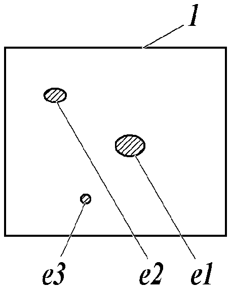
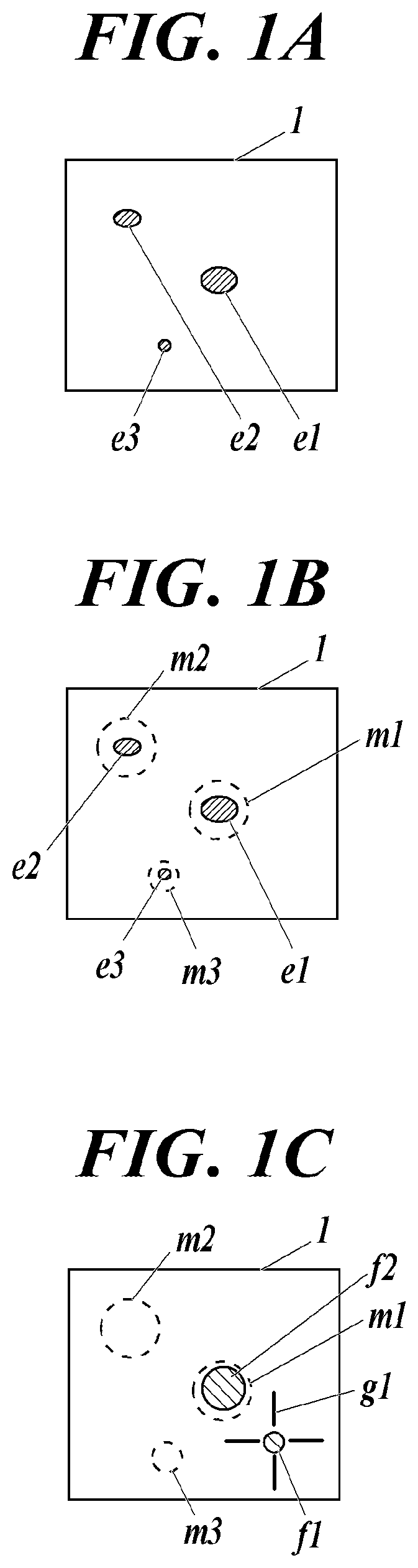
[0024] FIG. 1A is a schematic diagram of an inspection target (or a detection result) in a step of an inspection A in a non-destructive inspection method according to an embodiment of the present invention.
[0025] FIG. 1B is a schematic diagram of an inspection target (or a detection result) in a step of forming a mark in a non-destructive inspection method according to an embodiment of the present invention.
[0026] FIG. 1C is a schematic diagram of an inspection target (or a detection result) in a step of other inspection in a non-destructive inspection method according to an embodiment of the present invention.
DESCRIPTION OF EMBODIMENTS
[0027] Hereinafter, embodiments of the present invention will be described with reference to the drawings. The following is an embodiment of the present invention and does not limit the present invention.
[0028] An inspection target is inspected using multiple non-destructive inspection means of different types. The multiple different types of non-destructive inspection means include any two or more of an X-ray imaging means, a magnetic field distribution measurement means, a thermography imaging means, and a hardness measurement means. In the example mainly described in the present embodiment are used an X-ray imaging device including an X-ray imaging means and a magnetic field distribution measurement device including a magnetic field distribution measurement means. The X-ray imaging device and the magnetic field distribution measurement device are separate from each other, and the inspection target moves between and inspected by them. Therefore, the placement of the inspection target with respect to an origin position differs between devices.
[0029] An inspection A, marking, and other inspections B, C, are performed in this order.
[0030] First, the inspection A is performed (FIG. 1A). For example, in the inspection A, peculiar portions e1, e2, and e3 are detected in an inspection target 1 (for example, in an LIB mentioned above) as shown in FIG. 1A. The peculiar portions may be an abnormal portion, a portion suspected of an abnormal portion, a portion in need of a further inspection, or the like.
[0031] Next, marking positions are determined in the detection result (FIG. 1A) in the inspection A and stored in the device. At the same time, corresponding to the respective marking positions, marks m1, m2, and m3 that are detectable in the inspections B, C are formed fixedly (FIG. 1B).
[0032] For example, the inspection A includes detection using an X-ray imaging device and the inspection B includes detection using a magnetic field distribution measuring device. Here, a magnetic material is used as the material constituting the marks. For example, an ink including a magnetic material is used to print the marks.
[0033] The X-ray imaging device may be an X-ray Talbot imaging device (see Patent Document 2). When an X-ray Talbot imaging device is used, an X-ray inspection result with a higher contrast than usual can be obtained.
[0034] The magnetic sensor mounted on the magnetic field distribution measuring device may be an MR sensor, an MI sensor, a TMR sensor (a tunnel type magnetoresistive sensor), or the like. A TMR sensor (tunnel type magnetoresistive sensor) having high sensitivity is preferably used.
[0035] The inspections are performed with separate devices, and a printing device (for example, an inkjet printer) are attached or linked to each of the devices. The printing device is used for forming the marks fixedly each at a position of coordinates determined on the inspection target in the detection result in the inspection.
[0036] Next, in the inspection B, the detection result of the inspection target 1 including the marks m1, m2, and m3 is detected as shown in FIG. 1C, for example. Peculiar portions f1 and f2 are detected in the inspection target 1 as shown in FIG. 1C.
[0037] Next, the detection results in the inspections A and B are overlapped, compared, and examined in a correct positional relationship in reference to the positions of the marks m1, m2, and m3. That is, in reference to the positions of the marks m1, m2, and m3 stored in the inspection A and in reference to the marks m1, m2, and m3 detected in the inspection B, the same positions in the detection results in the inspections A and B are contrasted. For example, coordinates (x1, y1) are determined on a plane having X- and Y-coordinate axes and defined in reference to the marks m1, m2, and m3. Abnormality is determined by contrasting, comparing, and examining a detected value(s) at the coordinates (x1, y1) in a detection result in the inspection A and the detected value at the coordinates (x1, y1) in a detection result in the inspection B. For example, because the peculiar portion e1 and peculiar portion 12 respectively in FIGS. 1A and 1C are at the same coordinates, the portions are determined to be an abnormal portion.
[0038] The detection results in the inspections A and B may be further used for detailed analysis of a failure in the inspection C (for example, cross-sectional TEM). Here; a portion to be analyzed can be selected in reference to the marks m1, m2, and m3.
[0039] The detection result in the inspection B with a new mark g1 added thereto may be used in and after the following inspection C. That is, in and after the inspection C, a portion to be analyzed can be selected in reference to the marks m1, m2, m3 and the mark g1.
[0040] Thereafter, further inspection(s) D . . . can be performed in the same manner, and the number of marks can be increased as the number of inspections increases. The marks m1, m2, and m3 for positioning are determined after the detection result in the inspection A is obtained, and are formed on the inspection target 1 before the detection in the inspection B.
[0041] As a result, failure cause analysis and shipping inspection can be efficiently performed through accurate understanding and comparison of the same position of the inspection target in the multiple different types of inspections.
[0042] The marks m1, m2, and m3 may include information not related to position reference. For example, the marks m1, m2, and m3 may be one-dimensional or two-dimensional barcodes each representing an individual identification number(s). Prior to the inspection A, the information is allocated to the marks m1, m2, and m3 and shared by the device performing the inspection A and the printing device attached or linked thereto. The printing device fixedly forms the marks m1, m2, and m3 including the information on the inspection target 1. Thereafter, each inspection device reads the information from the marks (code recording media) included in the detection result in and after the inspection B. This is realized by forming the marks so as to be commonly read by all the non-destructive inspection means in and after the inspection B. As a result, because the individual identification number(s) is present together with the inspection target in the detection results, it is easy and reliable to check the detection results of the same individual.
[0043] The non-destructive inspection means is not limited to the X-ray imaging means or the magnetic field distribution measurement means, as long as it can measure an in-plane distribution non-destructively and obtain a detection image as a result. For example, it may be a thermographic imaging means that measures a heat distribution by thermography, a hardness measuring means that inspects hardness at each coordinate point with a stylus, or the like. In thermography, the mark may be formed with an ink material having emissivity which is different from the surface of the inspection target. When a stylus is used, the mark may be formed with an ink material having hardness which is different from the inspection target. A combination of them may be used as an ink. For example, the mark may be formed with an ink including two or more or all of materials each having magnetism, emissivity different from the surface of the inspection target, and hardness different from the inspection target.
[0044] In the inspection method, a peculiar portion(s) may be detected in the prior inspection A, and the peculiar portion found in the inspection A may be finely and intensively inspected in the following inspection B. That is, in this method, the peculiar portion is specified based on a detection result using one of the multiple non-destructive inspection means, and then intensively inspected using another non-destructive inspection means. "Intensive inspection of the peculiar portion" means that only the peculiar portion is the target to be inspected or that the peculiar portion is inspected with a higher resolution than the other portions.
[0045] For example, peculiar portions e1, e2, and e3 are specified based on the result of inspecting the entire surface of the inspection target using an X-ray imaging device in the inspection A, and then finely measured using a magnetic field distribution measuring device in the inspection B. While an entire surface can be captured at a time and inspected in a short time in the X-ray imaging, inspection of a large area may take a lot of time in the magnetic field distribution measurement, for example, when a measurement head performs measurement during a scan. In such a case, the inspection time can be shortened when the magnetic field distribution measuring device finely examines only the peculiar portion(s) detected in the X-ray imaging.
[0046] As described above, according to the non-destructive inspection method of the present embodiment, when an inspection target is inspected using multiple different types of non-destructive inspection means, positions specified in a detection result of the inspection target using each of the non-destructive inspection means can be matched with each other easily and accurately. As a result, multifaceted judgment can be made based on detection results by the multiple different types of non-destructive inspection means.
[0047] In spite of the above embodiments, the number of the other inspection(s) after the prior inspection A before marking may be one. Furthermore, when two or more other inspections are performed, that is, when there are two or more other non-destructive inspection means, the inspections can be performed at the same time without any particular problems in carrying out the present invention.
[0048] In the above embodiment, the marks m1, m2, and m3 and the mark g1 have shapes (a circle, an aiming symbol, or the like) each indicating a peculiar portion detected in the corresponding inspection, and the peculiar portions are determined based on their shapes (for example, a peculiar portion is determined to be in a circle) according to a rule consistently used in the inspections. Otherwise, regardless of the presence or position of the peculiar portion according to the inspection A, the marks m1, m2, and m3 required for position determination may be at a predetermined position, for example, at an edge of the inspection target 1, such that the coordinate information of a peculiar portion with reference to the marks m1, m2, and m3 is consistently used in the inspections. In this way, when a peculiar portion cannot be detected in the inspection A, the marking positions of the marks m1, m2, and m3 is not limited, but may be determined in advance (for example, determined to be an edge). The marking positions of the marks m1, m2, and m3 may be determined in advance (for example, determined to be an edge) only in a case where no peculiar portion is found in the inspection A or in all cases.
INDUSTRIAL APPLICABILITY
[0049] The present invention can be applied to a non-destructive inspection method of a lithium ion battery and the like.
REFERENCE SIGNS LIST
[0050] 1 INSPECTION TARGET [0051] e1, e2, e3 PECULIAR PORTION [0052] f1, f2 PECULIAR PORTION [0053] m1, m2, m3 MARK
* * * * *
D00000
D00001
XML
uspto.report is an independent third-party trademark research tool that is not affiliated, endorsed, or sponsored by the United States Patent and Trademark Office (USPTO) or any other governmental organization. The information provided by uspto.report is based on publicly available data at the time of writing and is intended for informational purposes only.
While we strive to provide accurate and up-to-date information, we do not guarantee the accuracy, completeness, reliability, or suitability of the information displayed on this site. The use of this site is at your own risk. Any reliance you place on such information is therefore strictly at your own risk.
All official trademark data, including owner information, should be verified by visiting the official USPTO website at www.uspto.gov. This site is not intended to replace professional legal advice and should not be used as a substitute for consulting with a legal professional who is knowledgeable about trademark law.