Substrate Processing Apparatus
Jeong; WonKi ; et al.
U.S. patent application number 16/938868 was filed with the patent office on 2021-02-04 for substrate processing apparatus. The applicant listed for this patent is ASM IP Holding B.V.. Invention is credited to HaSeok Jang, WonKi Jeong, JuIll Lee.
| Application Number | 20210035786 16/938868 |
| Document ID | / |
| Family ID | 1000005007964 |
| Filed Date | 2021-02-04 |


View All Diagrams
| United States Patent Application | 20210035786 |
| Kind Code | A1 |
| Jeong; WonKi ; et al. | February 4, 2021 |
SUBSTRATE PROCESSING APPARATUS
Abstract
A substrate processing apparatus having an improved exhaust structure includes a reaction space formed between a processing unit and a substrate support unit, an exhaust unit surrounding the reaction space, an exhaust port with a channel inside, a partition wall with an exhaust line inside, wherein the channel of the exhaust port connects the exhaust unit and the exhaust line.
| Inventors: | Jeong; WonKi; (Cheonan-si, KR) ; Lee; JuIll; (Cheonan-si, KR) ; Jang; HaSeok; (Hwaseong-si, KR) | ||||||||||
| Applicant: |
|
||||||||||
|---|---|---|---|---|---|---|---|---|---|---|---|
| Family ID: | 1000005007964 | ||||||||||
| Appl. No.: | 16/938868 | ||||||||||
| Filed: | July 24, 2020 |
Related U.S. Patent Documents
| Application Number | Filing Date | Patent Number | ||
|---|---|---|---|---|
| 62880622 | Jul 30, 2019 | |||
| Current U.S. Class: | 1/1 |
| Current CPC Class: | H01L 21/67017 20130101; C23C 16/4412 20130101; H01J 37/32715 20130101; H01J 37/32513 20130101; H01J 37/32834 20130101; C23C 16/50 20130101; H01J 2237/332 20130101; H01J 37/32449 20130101 |
| International Class: | H01J 37/32 20060101 H01J037/32; H01L 21/67 20060101 H01L021/67; C23C 16/44 20060101 C23C016/44; C23C 16/50 20060101 C23C016/50 |
Claims
1. A substrate processing apparatus comprising: a partition wall having an exhaust line therein; a substrate support unit included in the partition wall; a processing unit disposed above the substrate support unit; an exhaust unit connected to a reaction space between the substrate support unit and the processing unit; and an exhaust port connected to at least a part of the exhaust unit, wherein the exhaust port is configured to connect the exhaust unit and the exhaust line inside the partition wall.
2. The substrate processing apparatus of claim 1, wherein an exhaust space connected to the reaction space is defined in the exhaust unit.
3. The substrate processing apparatus of claim 2, wherein the exhaust unit comprises a barrier wall that limits a side portion of the reaction space.
4. The substrate processing apparatus of claim 3, wherein the exhaust unit further comprises: an outer wall disposed parallel to the barrier wall; and a connection wall extending to connect the barrier wall and the outer wall.
5. The substrate processing apparatus of claim 4, wherein the connection wall provides a contact surface between the exhaust unit and the processing unit.
6. The substrate processing apparatus of claim 1, further comprising: a first surface and a second surface, wherein the exhaust line extends along an edge between the first surface and the second surface.
7. The substrate processing apparatus of claim 1, further comprising: a support portion configured to support the processing unit and the exhaust unit, wherein the support portion is disposed between the exhaust port and the partition wall.
8. The substrate processing apparatus of claim 7, wherein the support portion comprises a path connecting the exhaust port and the exhaust line.
9. The substrate processing apparatus of claim 8, wherein a sectional area of the path and a sectional area of the exhaust line are the same.
10. The substrate processing apparatus of claim 7, further comprising: a sealing member disposed between the support portion and the partition wall.
11. The substrate processing apparatus of claim 7, further comprising: a gas flow control ring disposed on the support portion.
12. The substrate processing apparatus of claim 11, wherein the gas flow control ring is disposed between the support portion and the substrate support unit to be spaced apart from the substrate support unit.
13. The substrate processing apparatus of claim 11, wherein the gas flow control ring is disposed to be slidable on the support portion.
14. The substrate processing apparatus of claim 1, wherein the exhaust port comprises a channel extending in a first direction toward the exhaust unit and in a second direction different from the first direction.
15. The substrate processing apparatus of claim 1, wherein the exhaust unit extends to surround the reaction space, and the exhaust port is disposed to communicate with a part of circumference of the exhaust unit.
16. The substrate processing apparatus of claim 15, wherein a gas supplied to a center of the reaction space via the processing unit is radially distributed to move toward the exhaust unit, and the gas moves along an inner space of the exhaust unit and is discharged through the exhaust port.
17. A substrate processing apparatus comprising: a partition wall having a first exhaust line, a second exhaust line, a third exhaust line, and a fourth exhaust line therein; a first substrate support unit accommodated in the partition wall; a first processing unit on the first substrate support unit; a first exhaust unit connected to the first reaction space between the first substrate support unit and the first processing unit; a first exhaust port connected to at least a part of the first exhaust unit; a second substrate support unit accommodated in the partition wall; a second processing unit on the second substrate support unit; a second exhaust unit connected to a second reaction space between the second substrate support unit and the second processing unit; a second exhaust port connected to at least a part of the second exhaust unit; a third substrate support unit accommodated in the partition wall; a third processing unit on the third substrate support unit; a third exhaust unit connected to a third reaction space between the third substrate support unit and the third processing unit; a third exhaust port connected to at least a part of the third exhaust unit; a fourth substrate support unit accommodated in the partition wall; a fourth processing unit on the fourth substrate support unit; a fourth exhaust unit connected to a fourth reaction space between the fourth substrate support unit and the fourth processing unit; and a fourth exhaust port connected to at least a part of the fourth exhaust unit, wherein the first exhaust port is configured to connect the first exhaust unit and the first exhaust line in the partition wall, the second exhaust port is configured to connect the second exhaust unit and the second exhaust line in the partition wall, the third exhaust port is configured to connect the third exhaust unit and the third exhaust line in the partition wall, and the fourth exhaust port is configured to connect the fourth exhaust unit and the fourth exhaust line in the partition wall.
18. The substrate processing apparatus of claim 17, further comprising: a first connection port connecting the first exhaust line and the second exhaust line; a second connection port connecting the third exhaust line and the fourth exhaust line; an exhaust pump; and an external path connecting the first connection port and the exhaust pump and connecting the second connection port and the exhaust pump, wherein the external path is disposed outside the partition wall.
19. A substrate processing apparatus comprising: a substrate support unit configured to support a substrate; a processing unit disposed above the substrate support unit and defining a reaction space between the substrate support unit and the processing unit; and an exhaust unit providing an exhaust space connected to the reaction space; and an exhaust port communicating with the exhaust unit, wherein the exhaust port comprises a channel extending in a first direction toward the exhaust unit and a second direction different from the first direction.
20. The substrate processing apparatus of claim 19, further comprising: a partition wall having an exhaust line therein, wherein the channel communicates with the exhaust line of the partition wall.
Description
CROSS-REFERENCE TO RELATED APPLICATIONS
[0001] This application claims the benefit of U.S. Provisional Patent Application No. 62/880,622, filed on Jul. 30, 2019, in the U.S. Patent and Trademark Office, the disclosure of which is incorporated herein in its entirety by reference.
BACKGROUND
1. Field
[0002] One or more embodiments relate to a substrate processing apparatus, and more particularly, to a substrate processing apparatus having an improved exhaust structure.
2. Description of Related Art
[0003] In a semiconductor deposition process, a plasma process can be performed at a low temperature compared to a thermal process, and thus thermal shock to a semiconductor device may be reduced. Furthermore, as thermal shock applied to semiconductor deposition equipment decreases, durability of an apparatus and life of constituent components may be improved, and thus the plasma process is applied to numerous processes.
[0004] In a deposition process using plasma, plasma is generated by applying RF power to a reactive gas supplied to a reaction space to ionize the reactive gas. An ionized reactive gas is activated to react with a substrate, thereby forming a thin film on the substrate. Korean Patent Publication No. 10-2019-0032077 and Korean Patent No. 10-1680379 disclose the above deposition process using plasma.
[0005] Korean Patent Publication No. 10-2019-0032077 discloses an atomic layer deposition system as a deposition process using plasma. In detail, the document discloses an atomic layer deposition system having a structure in which the gas inside a reaction chamber is discharged through a pump connected to a pump pipe. To increase the efficiency of the plasma process as much as possible, plasma needs to be generated on the substrate in the reaction space. However, parasitic plasma that is generated in an area other than the reaction space, for example, an exhaust line, may cause degradation of the efficiency of the plasma process in the reaction space.
SUMMARY
[0006] One or more embodiments include a substrate processing apparatus which may prevent generation of parasitic plasma in an area, such as an exhaust space, other than the reaction space.
[0007] One or more embodiments include a substrate processing apparatus having a gas exhaust structure which implements efficient discharge by reducing the volume of an exhaust space.
[0008] Additional aspects will be set forth in part in the description which follows and, in part, will be apparent from the description, or may be learned by practice of the presented embodiments of the disclosure.
[0009] According to one or more embodiments, a substrate processing apparatus includes: a partition wall having an exhaust line therein; a substrate support unit included in the partition wall, a processing unit disposed above the substrate support unit, an exhaust unit connected to a reaction space between the substrate support unit and the processing unit, and an exhaust port connected to at least a part of the exhaust unit, wherein the exhaust port is configured to connect the exhaust unit and the exhaust line inside the partition wall.
[0010] An exhaust space connected to the reaction space may be defined in the exhaust unit.
[0011] The exhaust unit may include a barrier wall that limits a side portion of the reaction space.
[0012] The exhaust unit may further include an outer wall disposed parallel to the barrier wall, a connection wall extending to connect the barrier wall and the outer wall.
[0013] The connection wall may provide a contact surface between the exhaust unit and the processing unit.
[0014] The substrate processing apparatus may further include a first surface and a second surface, wherein the exhaust line extends along an edge between the first surface and the second surface.
[0015] The substrate processing apparatus may further include a support portion configured to support the processing unit and the exhaust unit, wherein the support portion is disposed between the exhaust port and the partition wall.
[0016] The support portion may include a path connecting the exhaust port and the exhaust line.
[0017] A sectional area of the path and a sectional area of the exhaust line may be the same.
[0018] The substrate processing apparatus may further include a sealing member disposed between the support portion and the partition wall.
[0019] The substrate processing apparatus may further include a gas flow control ring disposed on the support portion.
[0020] The gas flow control ring may be disposed between the support portion and the substrate support unit to be spaced apart from the substrate support unit.
[0021] The gas flow control ring may be disposed to be slidable on the support portion.
[0022] The exhaust port may include a channel extending in a first direction toward the exhaust unit and in a second direction different from the first direction.
[0023] The exhaust unit may extend to surround the reaction space, and the exhaust port may be disposed to communicate with a part of circumference of the exhaust unit.
[0024] A gas supplied to a center of the reaction space via the processing unit may be radially distributed to move toward the exhaust unit, and the gas may move along an inner space of the exhaust unit and may be discharged through the exhaust port.
[0025] According to one or more embodiments, a substrate processing apparatus includes a partition wall having a first exhaust line, a second exhaust line, a third exhaust line, and a fourth exhaust line therein, a first substrate support unit accommodated in the partition wall, a first processing unit on the first substrate support unit, a first exhaust unit connected to the first reaction space between the first substrate support unit and the first processing unit, a first exhaust port connected to at least a part of the first exhaust unit, a second substrate support unit accommodated in the partition wall, a second processing unit on the second substrate support unit, a second exhaust unit connected to a second reaction space between the second substrate support unit and the second processing unit, a second exhaust port connected to at least a part of the second exhaust unit, a third substrate support unit accommodated in the partition wall, a third processing unit on the third substrate support unit, a third exhaust unit connected to a third reaction space between the third substrate support unit and the third processing unit, a third exhaust port connected to at least a part of the third exhaust unit, a fourth substrate support unit accommodated in the partition wall, a fourth processing unit on the fourth substrate support unit, a fourth exhaust unit connected to a fourth reaction space between the fourth substrate support unit and the fourth processing unit, a fourth exhaust port connected to at least a part of the fourth exhaust unit, wherein the first exhaust port is configured to connect the first exhaust unit and the first exhaust line in the partition wall, the second exhaust port is configured to connect the second exhaust unit and the second exhaust line in the partition wall, the third exhaust port is configured to connect the third exhaust unit and the third exhaust line in the partition wall, and the fourth exhaust port is configured to connect the fourth exhaust unit and the fourth exhaust line in the partition wall.
[0026] The substrate processing apparatus may further include a first connection port connecting the first exhaust line and the second exhaust line, a second connection port connecting the third exhaust line and the fourth exhaust line, an exhaust pump, an external path connecting the first connection port and the exhaust pump and connecting the second connection port and the exhaust pump, wherein the external path is disposed outside the partition wall.
[0027] According to one or more embodiments, a substrate processing apparatus includes a substrate support unit configured to support a substrate, a processing unit disposed above the substrate support unit and defining a reaction space between the substrate support unit and the processing unit, an exhaust unit providing an exhaust space connected to the reaction space, an exhaust port communicating with the exhaust unit, wherein the exhaust port may include a channel extending in a first direction toward the exhaust unit and a second direction different from the first direction.
[0028] The substrate processing apparatus may further include a partition wall having an exhaust line therein, wherein the channel communicates with the exhaust line of the partition wall.
BRIEF DESCRIPTION OF THE DRAWINGS
[0029] These and/or other aspects will become apparent and more readily appreciated from the following description of the embodiments, taken in conjunction with the accompanying drawings in which:
[0030] FIGS. 1 and 2 schematically illustrate a substrate processing apparatus according to an embodiment;
[0031] FIG. 3 schematically illustrates a substrate processing apparatus according to another embodiment;
[0032] FIGS. 4 and 5 schematically illustrate substrate processing apparatuses according to embodiments;
[0033] FIGS. 6 and 7 are perspective views illustrating an exhaust duct and an inner cover that are separated from each other in a substrate processing apparatus according to an embodiment;
[0034] FIG. 8 is a perspective view illustrating an exhaust duct, an inner cover, and a conductive ring separated from one another in a substrate processing apparatus according to an embodiment;
[0035] FIGS. 9 to 11 schematically illustrate a substrate processing apparatus according to some embodiments; and
[0036] FIGS. 12 to 14 schematically illustrate a substrate processing apparatus according to embodiments.
DETAILED DESCRIPTION
[0037] Reference will now be made in detail to embodiments, examples of which are illustrated in the accompanying drawings, wherein like reference numerals refer to like elements throughout. In this regard, the present embodiments may have different forms and should not be construed as being limited to the descriptions set forth herein. Accordingly, the embodiments are merely described below, by referring to the figures, to explain aspects of the present description. As used herein, the term "and/or" includes any and all combinations of one or more of the associated listed items. Expressions such as "at least one of," when preceding a list of elements, modify the entire list of elements and do not modify the individual elements of the list.
[0038] Hereinafter, the embodiments of the present disclosure are described in detail with reference to the accompanying drawings.
[0039] Terms used in the present specification are used for explaining a specific embodiment, not for limiting the present disclosure. Thus, an expression used in a singular form in the present specification also includes the expression in its plural form unless clearly specified otherwise in context.
[0040] It will be understood that, although terms first, second, third, etc., may be used herein to describe various elements, components, regions, layers and/or sections, these elements, components, regions, layers and/or sections should not be limited by these terms. These terms are only used to distinguish one element, component, region, layer or section from another region, layer or section. Also, terms such as "include" or "comprise" may be construed to denote a certain characteristic, number, step, operation, constituent element, or a combination thereof, but may not be construed to exclude the existence of or a possibility of addition of one or more other characteristics, numbers, steps, operations, constituent elements, or combinations thereof. As used herein, the term "and/or" includes any and all combinations of one or more of the associated listed items.
[0041] Thus, a first element, component, region, layer or section discussed below could be termed a second element, component, region, layer or section without departing from the teachings of embodiments. In the drawings, the illustrated shapes may be modified according to, for example, manufacturing technology and/or tolerance. Thus, the embodiment of the present disclosure may not be construed to be limited to a particular shape of a part described in the present specification and may include a change in the shape generated during manufacturing, for example.
[0042] The attached drawings for illustrating preferred embodiments of the present disclosure are referred to in order to gain a sufficient understanding of the present disclosure, the merits thereof, and the objectives accomplished by the implementation of the present disclosure. In the drawings, the illustrated shapes may be modified according to, for example, manufacturing technology and/or tolerance. Thus, the embodiment of the present disclosure may not be construed to be limited to a particular shape of a part described in the present specification and may include a change in the shape generated during manufacturing, for example.
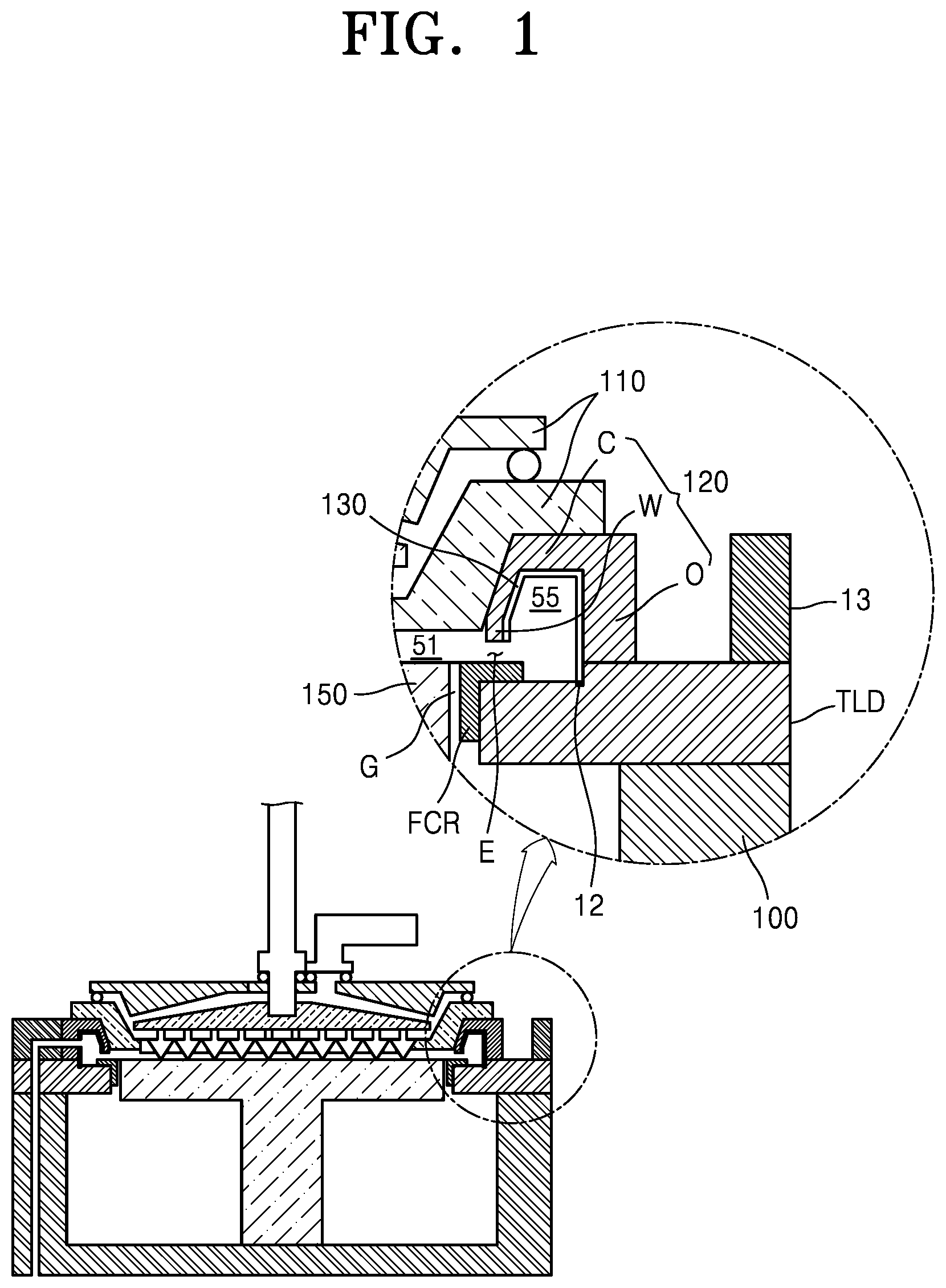
[0043] FIGS. 1 and 2 schematically illustrate a substrate processing apparatus according to an embodiment. FIG. 1 illustrates a substrate processing apparatus and a part of the substrate processing apparatus (a section of a portion of an exhaust unit 120 where no opening is formed). FIG. 2 illustrates the substrate processing apparatus and another part of the substrate processing apparatus (a section of a portion of the exhaust unit 120 where an opening OP is formed).
[0044] Referring to FIGS. 1 and 2, the substrate processing apparatus may include a partition wall 100, a substrate support unit 150, a processing unit 110, the exhaust unit 120, and a conductive extension portion 130. A conductive extension portion 130 may be omitted. A reaction space 51 and an exhaust space 55 connected to the reaction space 51 may be formed in the substrate processing apparatus.
[0045] The partition wall 100, which is a chamber for accommodating the substrate support unit 150, may be referred to as a chamber main body. In an embodiment, a reactor including the reaction space 51 may be referred to as an inner chamber, and the overall structure of the substrate processing apparatus surrounding a plurality of reactors, for example, four reactors, may be referred to as an external chamber. The exhaust line 18 may be provided inside the partition wall 100. In some embodiments, the exhaust line 18 may be formed to extend along the interior of a side wall of the partition wall 100. In an embodiment, the substrate processing apparatus may include a first surface and a second surface adjacent to the first surface, and the exhaust line 18 may extend along an edge between the first surface and the second surface. In additional embodiments, the exhaust line 18 may extend along the interior of a lower wall of the partition wall 100.
[0046] The processing unit 110 may be disposed above the substrate support unit 150 configured to support a substrate. The reaction space 51 may be defined between the substrate support unit 150 and the processing unit 110. The processing unit 110 may function as a first cover for defining an upper surface of the reaction space 51. In other words, the first cover disposed above the substrate support unit 150 may include at least one processing unit 110.
[0047] The processing unit 110 may include members that perform appropriate functions based on the functions of the substrate processing apparatus. For example, when the substrate processing apparatus performs a deposition function, the processing unit 110 may include a reaction material supply portion, for example, a shower head assembly. In another embodiment, when a reactor performs a polishing function, the processing unit 110 may include a polishing pad.
[0048] The processing unit 110 may be a conductor and may be used as an electrode for generating plasma. In other words, the processing unit 110 may function as an electrode for generating plasma. The processing unit 110 of the above type (the processing unit 110 is used as an electrode) may be referred to as a gas supply electrode in the following description.
[0049] The substrate support unit 150 may be configured to provide an area on which an object to be processed (not shown) such as a semiconductor or a display substrate is placed. The substrate support unit 150 may be supported by a support portion (not shown) capable of moving up/down and rotating. Furthermore, the substrate support unit 150 may be a conductor and may be used as an electrode for generating plasma, that is, a counter electrode of the gas supply electrode.
[0050] The exhaust unit 120 may be disposed between the processing unit 110 and a support portion TLD. The exhaust unit 120 may extend to surround the reaction space 51. The exhaust unit 120 may be implemented by a non-conductive material, for example, an insulating material. In contrast, the support portion TLD may be implemented by a conductive material, for example a conductor. Accordingly, a potential difference may be formed between the exhaust unit 120 that is disposed between the processing unit 110 functioning as an electrode and the support portion TLD implemented by a conductor, and the exhaust space 55 in the exhaust unit 120. The potential difference may cause parasitic plasma, and as described below, as the conductive extension portion 130 is introduced in the exhaust unit 120, the above-mentioned potential difference may be offset, and thus generation of parasitic plasma may be prevented.
[0051] In an embodiment, the exhaust unit 120 may function as a second cover that defines a side surface of the reaction space 51. The second cover including the exhaust unit 120 may include the exhaust space 55 connected to the reaction space 51. Accordingly, the exhaust unit 120 may provide the exhaust space 55. Furthermore, the exhaust unit 120 may provide a space for accommodating the processing unit 110. When the processing unit 110 is accommodated in the space, the processing unit 110 may be in contact with the exhaust unit 120.
[0052] The exhaust unit 120 may include a barrier wall W disposed between the reaction space 51 and the exhaust space 55. A first surface, for example, an outer surface, of the barrier wall W, may define the reaction space 51, and a second surface, that is, an inner surface as a surface facing the first surface, of the barrier wall W, may define the exhaust space 55. For example, the reaction space 51 may be defined by the first surface of the barrier wall W, an upper surface of the substrate support unit 150, and a lower surface of the processing unit 110 that is the first cover. In other words, the side portion of the reaction space 51 may be limited by the barrier wall W of the exhaust unit 120.
[0053] The exhaust unit 120 may provide a part of a space for processing an object to be processed. For example, when the substrate processing apparatus performs a deposition function, the reaction space 51 for deposition may be defined by the exhaust unit 120. Furthermore, the exhaust space 55 may be defined in the exhaust unit 120.
[0054] The conductive extension portion 130 may be configured to prevent generation of parasitic plasma in the exhaust space 55. For example, the conductive extension portion 130 may extend surrounding at least a part of the exhaust space 55, or may be grounded. Accordingly, the exhaust space 55 may be surrounded by the conductive extension portion 130, and thus generation of parasitic plasma in the exhaust space 55 may be prevented.
[0055] The conductive extension portion 130 may extend from an inner surface of the exhaust space 55. The conductive extension portion 130 may extend from the barrier wall W. Furthermore, the conductive extension portion 130 may be disposed in contact with the exhaust unit 120 that is the second cover. As a detailed example, the conductive extension portion 130 may be in contact with the second surface, that is, an inner surface, of the barrier wall W that defines the exhaust space 55, and the conductive extension portion 130 may extend along the second surface.
[0056] In an example, the exhaust unit 120 may include a connection wall C and an outer wall O extending from the barrier wall W. The outer wall O of the exhaust unit 120 may be arranged parallel to the barrier wall W, and may be in contact with the support portion TLD. The connection wall C of the exhaust unit 120 may extend to connect the barrier wall W to the outer wall O. The connection wall C may provide a contact surface to the processing unit 110. The processing unit 110 that is the first cover and the exhaust unit 120 that is the second cover may be in contact with each other by the contact surface.
[0057] The conductive extension portion 130 may extend along the barrier wall W, the connection wall C, and the outer wall O of the exhaust unit 120. In other words, the conductive extension portion 130, as illustrated in FIG. 2, may extend to entirely surround the exhaust space 55, except an interval E adjacent to the barrier wall W connecting the reaction space 51 and the exhaust space 55 in a first section of the exhaust unit 120. The conductive extension portion 130 formed as above may be disposed between a center of the exhaust space 55 and the exhaust unit 120. In an additional embodiment, one surface of the conductive extension portion 130 disposed between the center of the exhaust space 55 and the exhaust unit 120 may be in contact with the exhaust unit 120.
[0058] In an optional embodiment, the conductive extension portion 130 may extend along the barrier wall W, the connection wall C, the outer wall O, and the support portion TLD. In other words, the conductive extension portion 130 may extend from the exhaust unit 120 toward the support portion TLD. Accordingly, the conductive extension portion 130 may be in contact with the support portion TLD. The conductive extension portion 130 may be electrically connected to the support portion TLD, and accordingly the conductive extension portion 130 and the support portion TLD may have the same electric potential. For example, when the support portion TLD is grounded, the conductive extension portion 130 may be grounded as well.
[0059] The conductive extension portion 130 may extend surrounding a part of the exhaust space 55 in a second section of the exhaust unit 120. For example, the conductive extension portion 130 may include an opening that provides communication channel between the exhaust space 55 and an exhaust path. In an example, the opening may be implemented in the form of a groove. In another example, the opening may be implemented in the form of a hole. In another example, the conductive extension portion 130 may have a first part and a second part with the opening therebetween, and the opening may be formed such that the first part and the second part are separated from each other, that is, the conductive extension portion 130 has a cut shape. In this case, the conductive extension portion 130 may extend in the form of an open ring in which at least a part of the conductive extension portion 130 is separated therefrom.
[0060] The conductive extension portion 130 may extend to have a circumference in a shape corresponding to the shape of a substrate. In this case, a first area defined by a circumference formed as the barrier wall W of the conductive extension portion 130 may be greater than a second area defined by the substrate. Furthermore, a third area defined by a circumference formed as the outer wall O of the conductive extension portion 130 may be greater than the first area defined by the barrier wall W and the second area defined by the substrate.
[0061] For example, when the substrate is a circular substrate, the barrier wall W of the conductive extension portion 130 may also extend to have a shape of a first circle. Furthermore, the outer wall O of the conductive extension portion 130 may also extend to have a shape of a second circle. In this case, a distance from a center of the reaction space 51 to the barrier wall W, that is, a radius of the first circle may be greater than a radius of the substrate. Furthermore, a distance from the center of the reaction space 51 to the outer wall O, that is, a radius of the second circle may be greater than a radius of the first circle.
[0062] In an optional embodiment, the substrate processing apparatus may further include a conductive ring 12. The conductive ring 12 may be electrically connected to the conductive extension portion 130. The conductive ring 12 may be disposed to contact the conductive extension portion 130. For example, the conductive ring 12 may be disposed to contact the conductive extension portion 130 and the support portion TLD between the conductive extension portion 130 and the support portion TLD. Accordingly, the conductive extension portion 130 may be electrically connected to the support portion TLD via the conductive ring 12. Accordingly, when the support portion TLD is grounded, the conductive extension portion 130 may be grounded as well.
[0063] In an optional embodiment, the conductive ring 12 may include an elastic body. In an example, the elastic body may be configured to have elasticity in a direction, for example, a vertical direction, extending from the conductive extension portion 130 to the support portion TLD. In another example, as illustrated in FIG. 2, the support portion TLD may include a groove, and the conductive ring 12 may be accommodated in the groove.
[0064] The support portion TLD may support the processing unit 110 and the exhaust unit 120 by contacting the exhaust unit 120. The support portion TLD may be supported by a partition wall 100. As such, the support portion TLD may support the processing unit 110 that is the first cover and the exhaust unit 120 that is the second cover, and the support portion TLD may function as a top lid that covers the external chamber by being supported by the partition wall 100.
[0065] The support portion TLD may be disposed between the partition wall 100 and the exhaust port 13. The support portion TLD may include a path P connecting the exhaust port 13 and the exhaust line 18 of the partition wall 100. In an embodiment, the sectional area of the path P and the sectional area of the exhaust line 18 may be substantially the same. For example, when the path P and the exhaust line 18 are formed in a circular shape, the diameter of the path P may be the same as the diameter of the exhaust line 18. In an additional embodiment, a sealing member (not shown) may be disposed between the support portion TLD and the partition wall 100. The sealing member may extend along the circumference of the path P or the circumference of the exhaust line 18, and thus prevent the leakage of a gas flowing from the path P to the exhaust line 18.
[0066] The support portion TLD may be disposed between the partition wall 100 and a cover, for example, the second cover including the exhaust unit 120. A flow control ring (FCR) may be disposed on the support portion TLD. Furthermore, the flow control ring FCR may be disposed between the support portion TLD and the substrate support unit 150. The flow control ring FCR may be disposed to be slidable on the support portion TLD. The flow control ring FCR may be spaced apart from the substrate support unit 150 forming a gap G, and pressure balance between the reaction space 51 and an inner space of the external chamber may be controlled by adjusting the gap G.
[0067] To achieve the pressure balance, a filling gas may be introduced toward the reaction space 51 from a lower space under the support portion TLD and the substrate support unit 150. By the filling gas, a gas curtain may be formed in a gap G between the substrate support unit 150 and a gas flow control ring FCR. The gas curtain may prevent the gas in the reaction space 51 from being introduced into the lower space.
[0068] In an embodiment, the filling gas may be a gas different from the gas supplied through the processing unit 110. For example, the filling gas may be an inert gas such as nitrogen or argon. In some embodiments, the filling gas may be a gas having a discharge rate lower than the discharge rate of the gas supplied to the reaction space 51 through the processing unit 110. When plasma is generated in the reaction space 51, the filling gas having a low discharge rate may prevent generation of parasitic plasma in the lower space under the support portion TLD and the substrate support unit 150. The barrier wall W may provide a gap E connecting the reaction space 51 and the exhaust space 55. For example, the gap E may be formed between the exhaust unit 120 and the flow control ring FCR. The gap E may function as a channel between the reaction space 51 and the exhaust space 55. Accordingly, the reaction space 51 and the exhaust space 55 may communicate with each other through the channel.
[0069] In the above structure, the gas in the reaction space 51 is discharged through the exhaust space 55 in a lateral direction. In other words, the gas of the reaction space 51 may be discharged through the exhaust space 55, the opening OP, a channel in the exhaust port 13, the path P of the support portion TLD, and the exhaust line 18 of the partition wall 100. The gas exhaust structure may have an improved gas discharge efficiency compared with a downstream gas exhaust structure, that is, a structure in which the gas of the reaction space 51 is discharged through the lower space under the substrate support unit 150. In detail, a lateral gas exhaust structure according to embodiments may have the following technical advantages.
[0070] 1) Reduction of volume of exhaust space--While in a downstream gas exhaust structure, the lower space under the substrate support unit 150 is used as a space for exhaust, in contrast, in the lateral gas exhaust structure, only the exhaust space 55 in the exhaust unit 120 is used as a space for exhaust. Accordingly, the volume of the exhaust space is reduced. Accordingly, the atomic layer deposition process which requires a fast switching of different gases may be facilitated, and a contamination source due to a residual gas may be reduced.
[0071] 2) Improvement of exhaust speed--As the volume of the exhaust space is reduced, the amount of an exhaust gas may be reduced, and consequently the exhaust speed may be improved.
[0072] 3) Reduction of residual gas--As a larger amount of gas may be discharged for a limited time, the residual gas in the reaction space and the exhaust space may be reduced.
[0073] 4) Improvement of durability--Durability may be improved due to the reduction of a residual gas. Furthermore, as the residual gas having reactivity or the residual gas which may be corrosive is not discharged through the lower space, the life of components located in the lower space may be extended.
[0074] 5) Prevention of leakage of gas--As the exhaust gas is discharged through the interior of the chamber wall, that is, through the exhaust line 18 of the partition wall 100, the leakage of an exhaust gas may be prevented.
[0075] Referring back to FIG. 2, a part of the exhaust unit 120 that is the second cover may communicate with an exhaust port 13. The exhaust port 13 may be connected to at least a part of the exhaust unit 120. For example, the exhaust port 13 may be disposed to communicate with a part of the circumference of the exhaust unit 120 (see FIG. 14). Accordingly, a gas in a part of the exhaust space 55 may be exhausted through the exhaust port 13.
[0076] In detail, the gas supplied to the center of the reaction space 51 through the processing unit 110 may be radially distributed. Accordingly, the radially distributed gas may move toward the exhaust space 55 of the exhaust unit 120. As the exhaust port 13 is connected to a part of the circumference of the exhaust unit 120, the gas radially distributed may flow toward the exhaust space 55 along an inner path of the exhaust unit 120. The gas flowing along the inner path of the exhaust unit 120 may be discharged through the opening OP and the exhaust port 13.
[0077] The exhaust port 13 may include a channel extending in a first direction toward the exhaust unit 120 and a second direction different from the first direction. In an embodiment, a channel having an L shape or an L-like shape may be formed in the exhaust port 13. Accordingly, the gas in the exhaust space 55 may be introduced in a lateral direction toward the exhaust port 13 and exhausted in a downward direction. In another example, the gas in the exhaust space 55 may be introduced in the lateral direction and exhausted in an upward direction. The gas exhausted through the exhaust port 13 may be transferred to an exhaust pump (not shown) through the exhaust line 18, and the gas may be exhausted to the outside by the exhaust pump.
[0078] FIG. 3 schematically illustrates a substrate processing apparatus according to another embodiment. The substrate processing apparatus according to the present embodiment may be a modified example of the substrate processing apparatus according to the above-described embodiment. Redundant descriptions between the embodiments are omitted.
[0079] Referring to FIG. 3, in the substrate processing apparatus, a contact wall 20 and the substrate support unit 150 may form the reaction space 51 while having face-contact and face-sealing. The substrate is mounted on the substrate support unit 150 and for loading/unloading the substrate, a lower portion of the substrate support unit 150 may be connected to an apparatus (not shown) capable of moving up/down.
[0080] The exhaust space 55 according to the present embodiment may be formed on the reaction space 51. In this case, the exhaust unit 120 that forms an exhaust space and the conductive extension portion 130 that extends in contact with the exhaust unit 120 may be formed above the reaction space 51. For example, the exhaust unit 120 and the conductive extension portion 130 may be formed above the processing unit 110.
[0081] The barrier wall W may be disposed between the reaction space 51 and the exhaust space 55. The first surface of the barrier wall W, for example, a face facing the processing unit 110, may define the reaction space 51. The second surface, that is, the surface opposite to the first surface, of the barrier wall W may define the exhaust space 55. For example, the reaction space 51 may be defined by the first surface of the barrier wall W, the upper surface of the substrate support unit 150, and the lower surface of the processing unit 110.
[0082] The barrier wall W may provide the gap E connecting the reaction space 51 and the exhaust space 55. As described above, the gap E may function as a communicating channel connecting between the reaction space 51 and the exhaust space 55.
[0083] The conductive extension portion 130 may extend along the second surface of the barrier wall W. The conductive extension portion 130 may extend to entirely surround the exhaust space 55, except the gap E adjacent to the barrier wall W. The conductive extension portion 130 may be grounded, and accordingly, generation of parasitic plasma in the exhaust space 55 may be prevented. Accordingly, power loss due to the generation of parasitic plasma may be prevented.
[0084] FIGS. 4 and 5 schematically illustrate substrate processing apparatuses according to embodiments. The substrate processing apparatuses according to the embodiments may be modified examples of the substrate processing apparatus according to the above-described embodiment. Redundant descriptions between the embodiments are omitted below.
[0085] Referring to FIG. 4, a reactive gas may be supplied to a reaction space 9 via a gas inlet 8 and a gas supply plate 3. The reactive gas may react with a substrate (not shown), thereby forming a thin film on the substrate placed on a heater block 4. Then, the reactive gas may be exhausted to the outside though an exhaust space 10 in the exhaust duct 5, via a gap formed between the reaction space 9 and an exhaust duct 5.
[0086] In an embodiment, the exhaust duct 5 and a flow control ring (FCR) 6 may include a non-conductive material or ceramic. The gas supply plate 3 may be a showerhead, and may be connected to an RF rod 2 to function as an upper electrode. The heater block 4 may be connected to a ground to function as a lower electrode.
[0087] In a plasma process, the reactive gas introduced into the reaction space 9 may be excited by RF power supplied through the RF rod 2 and the gas supply plate 3. The excited reactive gas may be ionized, and thus plasma may be generated. Plasma A generated in the reaction space 9 may contribute to the process on the substrate, but may be generated in the exhaust space 10 too.
[0088] The plasma A in the reaction space 9 may be generated due to a potential difference between an upper electrode 3 and a lower electrode 4 connected to a ground. Likewise, a potential difference is generated between the upper electrode 3 and a top lid 7 facing the upper electrode 3 and connected to the ground, and thus plasma B may be generated in the exhaust space 10.
[0089] The plasma B generated in the exhaust space 10 may be referred to as parasitic plasma, which does not contribute to a substrate processing process, but deteriorates the efficiency of the plasma A in reaction space. For example, as part of RF power generated by an RF generator is used for generation of parasitic plasma, the RF power contributing to an actual reaction is reduced that much. Accordingly, efficiency of the plasma process may deteriorate, and thus the substrate process may be unstable.
[0090] In contrast, referring to FIG. 5, in a substrate processing apparatus according to an embodiment, an inner cover 11 may be inserted into the exhaust space 10 in the exhaust duct 5. In detail, the inner cover 11 may be inserted between the exhaust duct 5 and a central portion of the exhaust space 10. The inner cover 11 may include a conductive material, for example, a metal material.
[0091] In an embodiment, the conductive ring 12 may be inserted in a step corner portion between the top lid 7 and the flow control ring 6. The inner cover 11 and the conductive ring 12 may be in contact with each other, and thus the inner cover 11 and the top lid 7 are electrically connected to each other. Accordingly, the potential difference may be removed between the inner cover 11 and the top lid 7.
[0092] In an additional embodiment, the inner cover 11 may be in a close contact with the exhaust duct 5 with no space between the exhaust duct 5 and the inner cover 11. Accordingly, even when a gas exists in the exhaust space 10, the inner cover 11 may be located in a ground region as the top lid 7. Also, as no space exists between the exhaust duct 5 and the inner cover 11, in the plasma process, parasitic plasma may not be generated in the exhaust space 10.
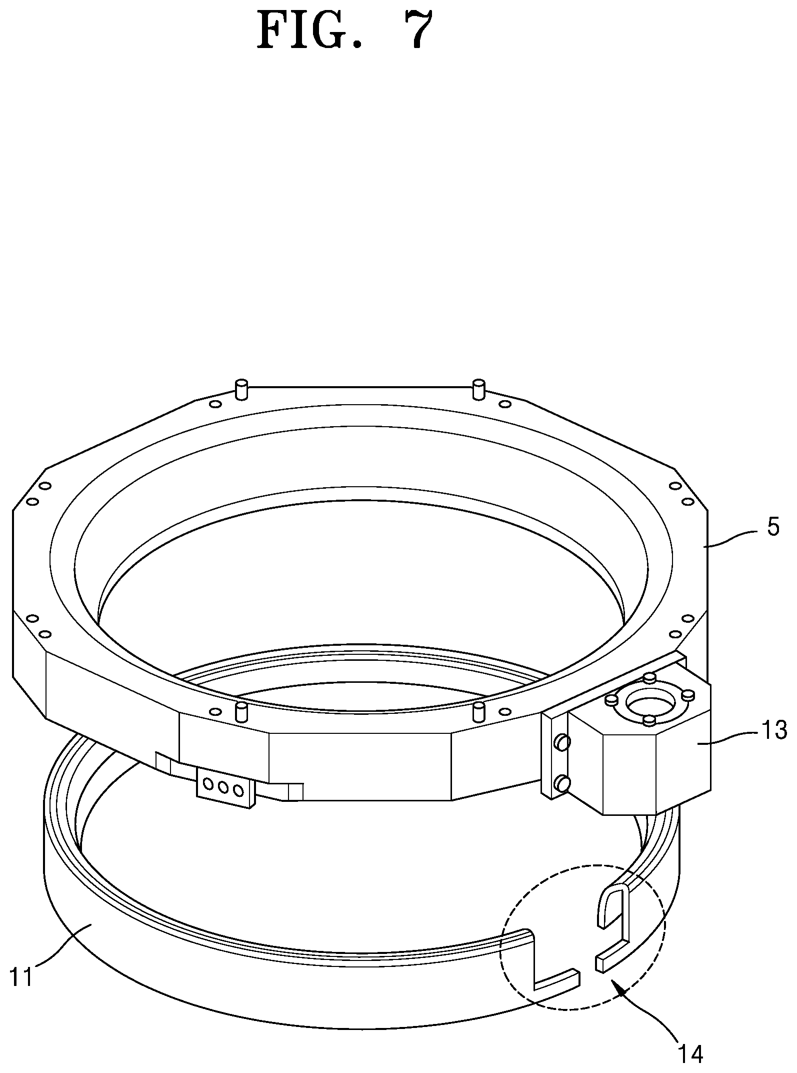
[0093] FIGS. 6 and 7 are exploded views illustrating that the exhaust duct 5 and the inner cover 11 included in a substrate processing apparatus according to an embodiment are separated from each other. The exhaust duct 5 and the inner cover 11 according to the embodiments may be modified examples of the exhaust unit and the conductive extension portion, respectively, according to the above-described embodiments. Redundant descriptions between the embodiments are omitted.
[0094] Referring to FIG. 6, the exhaust port 13 may be provided on a surface of the exhaust duct 5 and may be disposed between the exhaust space 10 and an exhaust line (not shown). Accordingly, an exhaust gas may be discharged to the exhaust line via the exhaust port 13. The exhaust structure may correspond to the structures of FIGS. 1 and 2, that is, the structure in which the gas of the exhaust space 55 is discharged to the exhaust line implemented in the partition wall 100 via the exhaust port 13.
[0095] As it may be seen from the structure of the exhaust port 13 in FIG. 6, the exhaust line may be disposed in an upper surface of the exhaust port 13. The structure of the exhaust line is distinguished from the structure of the exhaust line being disposed in a lower surface of the exhaust port 13 in the embodiment of FIGS. 1 and 2.
[0096] In an embodiment, an open portion 14 may be implemented in a surface of the inner cover 11. The open portion 14 may have a structure in the form of a groove and be obtained by cutting off a part of the inner cover 11. In an optional embodiment, the open portion 14 may be implemented in the form of an opening O of FIG. 2.
[0097] The open portion 14 may be formed between the exhaust space 10 and the exhaust port 13 and may function as a path through which the exhaust gas is discharged to the exhaust port 13. Furthermore, the open portion 14 may provide a buffer space with respect to thermal expansion of the inner cover 11 in a high-temperature process.
[0098] FIG. 7 illustrates a modified example of the inner cover 11 of FIG. 6. Referring to FIG. 7, a part of the open portion 14 of the inner cover 11 may be cut off from the inner cover 11. In other words, a part of the open portion 14 in the form of a groove, which is obtained by cutting off a part of the inner cover 11, may separate the inner cover 11. In this case, the inner cover 11 may have a shape of an open ring in which at least some parts of the inner cover 11 are separated from each other.
[0099] In the high-temperature process, as a thermal expansion coefficient of the inner cover 11 that is conductive is greater than that of the exhaust duct 5 that is non-conductive, the exhaust duct 5 may be deformed or damaged as the inner cover 11 expands. However, as described above, by removing a partial area of the inner cover 11, even when the inner cover 11 is deformed due to the thermal expansion, the shape and arrangement of the inner cover 11 may be maintained. As a result, in the high-temperature process, the damage of the exhaust duct 5 may be prevented.
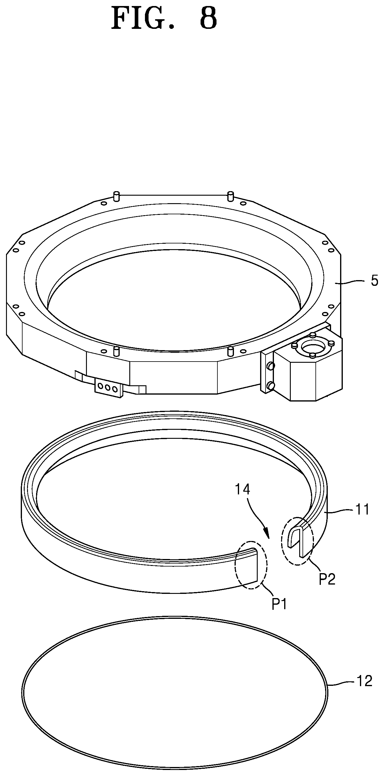
[0100] FIG. 8 is an exploded view illustrating that the exhaust duct 5, the inner cover 11, and the conductive ring 12 included in a substrate processing apparatus according to an embodiment are separated from one another. The exhaust duct 5, the inner cover 11, and the conductive ring 12 according to the embodiment may be modified examples of those of the above-described embodiments. Redundant descriptions between the embodiments are omitted.
[0101] Referring to FIG. 8, the inner cover 11 that is a conductive cover may have a first part P1 and a second part P2 with the open portion 14 that is an opening therebetween, and the first part P1 and the second part P2 may be separated from each other. While the open portion 14 of the inner cover 11 of FIG. 7 is implemented in the form of a groove by cutting off a part of the inner cover 11, the open portion 14 of the inner cover 11 of FIG. 8 is implemented by entirely cutting off a part of the inner cover 11.
[0102] The conductive ring 12 may be disposed under the inner cover 11. The conductive ring 12 may include a material having superior thermal conductivity, in detail, a metal material. The conductive ring 12 may perform the following two functions.
[0103] 1) Prevention of generation of parasitic plasma in the exhaust space 10: As the conductive ring 12 physically contacts the inner cover 11 disposed between the exhaust space 10 and the exhaust duct 5, a potential difference of the inner cover 11 may be the same as the potential difference of the top lid 7 connected to a ground electrode. Accordingly, the generation of parasitic plasma in the exhaust space 10 may be prevented.
[0104] 2) Buffering deformation of the inner cover 11 due to thermal expansion at high temperature: The inner cover 11 that includes a conductive material may be deformed and may expand at high temperature. The conductive ring 12 may buffer the inner cover 11 that thermally expands between the inner cover 11 and the top lid 7. Accordingly, the exhaust duct 5, the inner cover 11, and the top lid 7 may be prevented from being deformed or damaged due to thermal expansion.
[0105] To this end, the conductive ring 12 may be implemented by an elastic body having elasticity in a vertical direction. The elastic body may increase a contact area between the inner cover 11 and the conductive ring 12. Accordingly, the inner cover 11 may have the same potential difference as the ground electrode through the conductive ring 12.
[0106] As described above, according to the above-described embodiments, by inserting the inner cover and the conductive ring between the inner cover and the top lid in the exhaust space of the substrate processing apparatus and adjusting a potential difference therebetween, generation of parasitic plasma in the exhaust line of the reactor in the plasma process may be prevented. Furthermore, by introducing the structure of removing a part of the inner cover, the damage of the exhaust duct due to the thermal expansion of the inner cover in the high-temperature process may be prevented.
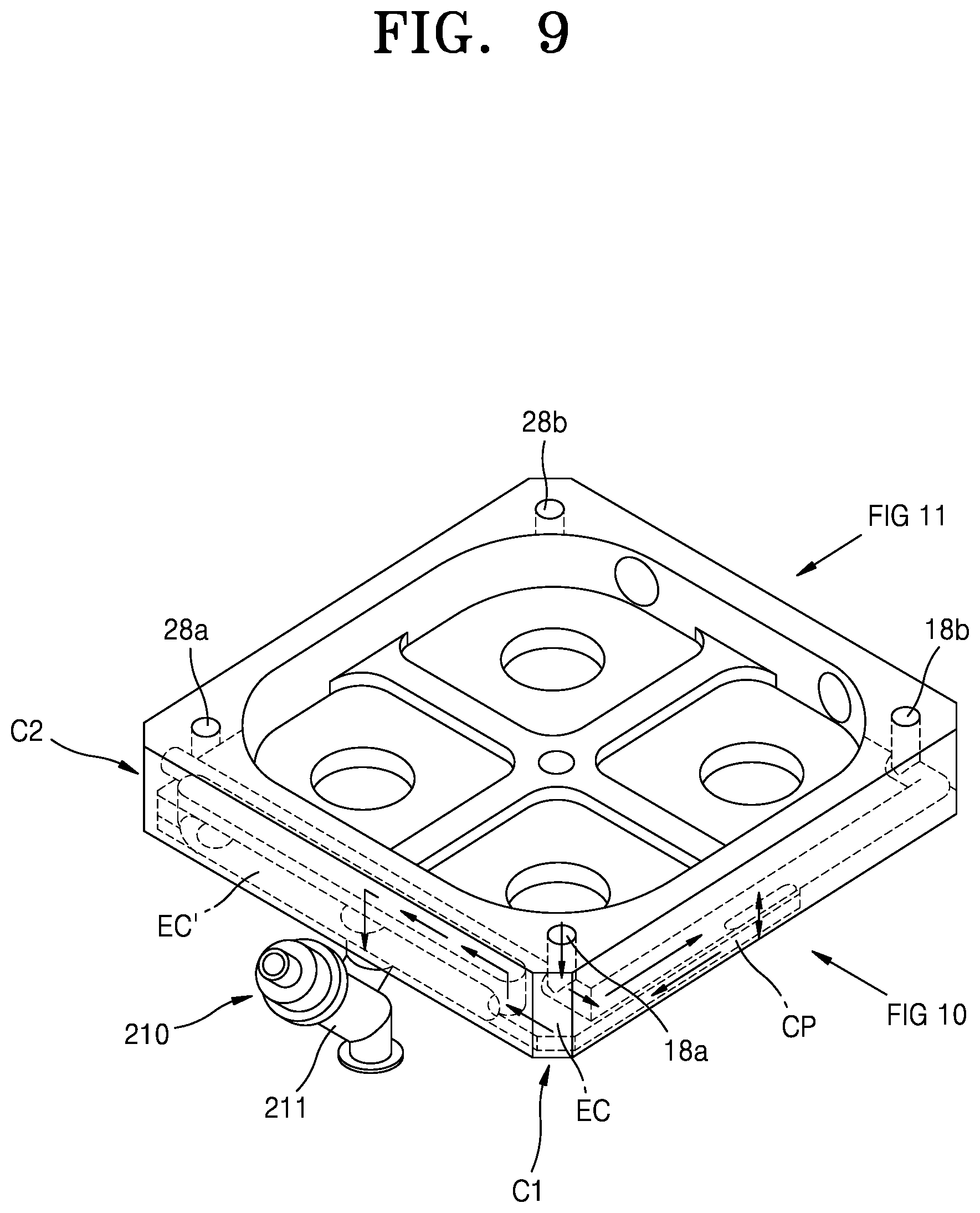
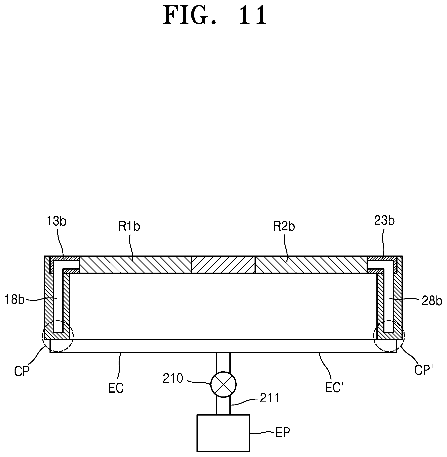
[0107] FIGS. 9 to 11 schematically illustrate a substrate processing apparatus according to some embodiments. In detail, FIG. 9 illustrates a portion, for example, the exhaust lines 18 and 28, a connection port CP, or an external path EC connected to the external pump, of the substrate processing apparatus except for the cover, that is, the processing unit and the exhaust unit, and the exhaust port. FIG. 10 illustrates the substrate processing apparatus of FIG. 9 viewed from a first direction, and FIG. 11 illustrates the substrate processing apparatus of FIG. 9 viewed from a second direction. The substrate processing apparatus according to these embodiments may be a modified example of the substrate processing apparatus according to the above-described embodiments. Redundant descriptions between the embodiments below may be omitted.
[0108] Referring to FIGS. 9 to 11, the exhaust lines 18 and 28 are formed in the interior of the partition wall 100. The exhaust lines 18 and 28 are connected to the external path EC through the connection port CP, and the external path EC is connected to a main exhaust path 211. Accordingly, the gas in the reaction space is discharged to an exhaust pump EP through the exhaust ports 13 and 23, the exhaust lines 18 and 28, the external path EC, and the main exhaust path 211.
[0109] As illustrated in FIG. 10, two reactors R1a and R1b in the first direction use inner exhaust lines 18; 18a, and 18b, and the other two reactors in a direction opposite to the first direction use other internal exhaust lines 28; 28a, and 28b. The two inner exhaust lines 18 and 28 are connected to the external path EC and EC' respectively through the connection ports CP and CP'. The external path EC may be implemented by one configuration or by a plurality of configurations.
[0110] In FIG. 10, it may be seen that four reactors use at least one external path EC, the main exhaust path 211, and the exhaust pump EP. The main exhaust path 211 may be further provided with an isolation valve 210. Accordingly, during a maintenance period, the isolation valve 210 may protect the exhaust pump EP from the outside atmosphere. Furthermore, a pressure control valve, for example, a throttle valve, may be added to the main exhaust path 211. The external path EC may be fixed and not to move in close contact with the lower surface of the partition wall 100 of the external chamber. In an optional embodiment, without the external path EC, the two inner exhaust lines 18 and 28 may be connected to each other in the interior of a bottom wall of the partition wall 100 of the external chamber so as to be directly connected to the main exhaust path 211.
[0111] Referring back to FIG. 9, the first external path EC connected to the first connection port CP may extend toward a first corner portion C1 of the external chamber under the partition wall 100. Furthermore, a second external path EC' connected to a second connection port (CP' of FIG. 11) may extend toward a second corner portion C2 of the external chamber under the partition wall 100. The exhaust pump EP may be disposed on one surface of the substrate processing apparatus, for example, corresponding to the center between the first corner portion C1 and the second corner portion C2. The first external path EC may extend from a portion extending from the first corner portion C1 toward the exhaust pump EP. Furthermore, likewise, the second external path EC' may extend from a portion extending form the second corner portion C2 toward the exhaust pump EP.
[0112] FIGS. 12 to 14 schematically illustrate a substrate processing apparatus according to embodiments. The substrate processing apparatus according to these embodiments may be a modified example of the substrate processing apparatus according to the above-described embodiments. Redundant descriptions between the embodiments below may be omitted.
[0113] Referring to FIG. 12, a top surface of a multi-reactor chamber 311 is illustrated. A plurality of reactors R are disposed inside the chamber 311 and one side of each reactor R is connected to an exhaust port 313. In FIG. 12, it may be seen that each reactor R is connected to each exhaust port 313.
[0114] A plurality of exhaust lines 318 may be formed in the interior of a partition wall of the chamber 311. For example, the chamber 311 may have a rectangular shape, and the exhaust lines 318 may include a first exhaust line 318a, a second exhaust line 318b, a third exhaust line 318c, and a fourth exhaust line 318d. In some embodiments, the first exhaust line to the fourth exhaust line may be disposed corresponding to four vertexes of the rectangle.
[0115] The chamber 311 may include a first reactor, a second reactor, a third reactor, and a fourth reactor. Each reactor may include a substrate support unit, a processing unit, an exhaust unit, and an exhaust port.
[0116] In detail, the first reactor may include a first substrate support unit (not shown) accommodated in the partition wall of the chamber 311, a first processing unit 312a on the first substrate support unit, a first exhaust unit 314a connected to a first reaction space between the first substrate support unit and the first processing unit 312a, and a first exhaust port 313a connected to at least a part of the first exhaust unit 314a. In this case, the first exhaust port 313a may be configured to connect the first exhaust unit 314a with the first exhaust line 318a in the interior of the partition wall.
[0117] The second reactor may include a second substrate support unit (not shown) accommodated in the partition wall of the chamber 311, a second processing unit 312b on the second substrate support unit, a second exhaust unit 314b connected to a second reaction space between the second substrate support unit and the second processing unit 312b, and a second exhaust port 313b connected to at least a part of the second exhaust unit 314b. In this case, the second exhaust port 313b may be configured to connect the second exhaust unit 314b with the second exhaust line 318b in the interior of the partition wall.
[0118] The third reactor may include a third substrate support unit (not shown) accommodated in the partition wall of the chamber 311, a third processing unit 312c on the third substrate support unit, a third exhaust unit 314c connected to a third reaction space between the third substrate support unit and the third processing unit 312c, and a third exhaust port 313c connected to at least a part of the third exhaust unit 314c. In this case, the third exhaust port 313c may be configured to connect the third exhaust unit 314c with a third exhaust line 318c in the interior of the partition wall.
[0119] The fourth reactor may include a fourth substrate support unit (not shown) accommodated in the partition wall of the chamber 311, a fourth processing unit 312d on the fourth substrate support unit, a fourth exhaust unit 314d connected to a fourth reaction space between the fourth substrate support unit and the fourth processing unit 312d, and a fourth exhaust port 313d connected to at least a part of the fourth exhaust unit 314d. In this case, the fourth exhaust port 313d may be configured to connect the fourth exhaust unit 314d with the fourth exhaust line 318d in the interior of the partition wall.
[0120] In connection with FIGS. 9 to 12, as described above, the substrate processing apparatus may further include the first connection port (CP in FIGS. 9 and 11) connecting the first exhaust line and the second exhaust line and the second connection port (CP' in FIGS. 9 and 11) connecting the third exhaust line and the fourth exhaust line. Furthermore, the substrate processing apparatus may further include at least one of the external paths (EC and EC' in FIG. 9) connecting the first connection port and the exhaust pump (EP in FIG. 10) and connecting the second connection port and the exhaust pump. The external paths EC and EC' may be disposed outside the partition wall of the chamber 311.
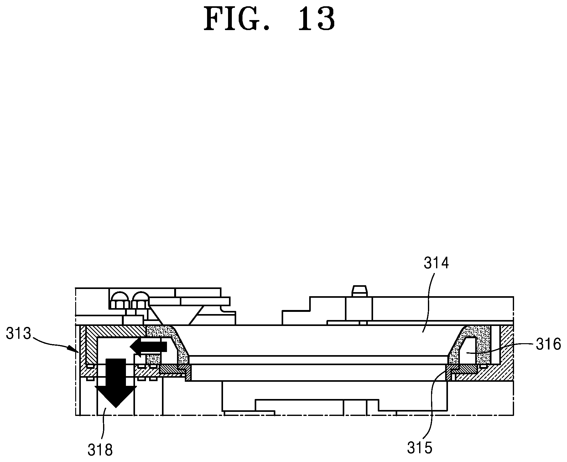
[0121] FIG. 13 illustrates a side perspective view of the reactor R. The reaction space of the reactor R may be defined to be a space surrounded by a cover having the exhaust unit 314 like an exhaust duct, a gas flow control ring (FCR) 315 disposed under the cover, a processing unit, for example, a shower head (not shown), disposed in an inner space surrounded by the exhaust unit 314, and a substrate support unit, for example, a heater (not shown), disposed to face the processing unit.
[0122] The exhaust unit 314 and the gas flow control ring 315 are spaced apart from each other forming an interval therebetween. For example, a separation space of about 1 mm may be formed, and the gas in the reaction space may be discharged to an exhaust pump (not shown) through the interval, that is, the separation space, and through an exhaust space 316 in the exhaust unit 314 and the exhaust port 313. The exhaust port 313 may include a channel through which the gas is discharged in a downward direction.
[0123] In FIGS. 13 and 14, a gas discharged path is indicated by arrows. As can be seen from the drawings, according to the present disclosure, the lateral gas exhaust structure in which the gas is discharged through the interior of the wall of the main body of the chamber is employed.
[0124] The gas supplied from an upper portion of the reactor toward the reaction space through the processing unit 312 may be radially distributed. The radially distributed gas may flow toward the exhaust space 316 of the exhaust unit 314. The gas radially distributed toward the exhaust space 316 may be discharged to the exhaust space 316 via a gap between the exhaust unit 314 and the gas flow control ring 315. The gas is discharged to the outside through the exhaust port 313 connected to one surface of the exhaust unit 314.
[0125] As such, the lateral gas exhaust structure is provided in which the gas remaining in the reaction space is discharged through a side surface of a reactor. In detail, the exhaust lines 318 formed in the interior of the partition wall are formed in the interiors of the side wall and the lower wall of the main body of the chamber 311 and the exhaust lines 318 and the exhaust unit 314 are communicated with each other through the exhaust port 313.
[0126] In general, a multi-reactor chamber according to the related art adopts a downstream exhaust structure in which a gas is discharged to a chamber lower space, in detail, a lower space of a substrate loading unit including a heater block on which a substrate is mounted. Although the above chamber has a merit of a simple apparatus configuration, such a downstream exhaust structure requires a large amount of time to completely discharge the gas due to a large volume of the chamber lower space. Furthermore, for the atomic layer deposition process that requires rapid switching of different gases, before the first discharged gas is completely discharged, a subsequently discharged different gas may be introduced into the chamber lower space. This causes chemical reaction between the remaining gas and the subsequently discharged gas, thereby generating unnecessary solid reaction byproducts. The reaction byproducts may cause contamination of a chamber and a substrate. Furthermore, as the reaction byproducts are deposited on a lower surface of the substrate loading unit including parts disposed in a lower portion of the chamber, for example, the heating block, the durability of the apparatus may deteriorate and the efficiency and performance of the moving unit may deteriorate. This may reduce a preventive maintenance cycle (PM cycle), and thus productivity may be decreased and maintenance costs may be increased.
[0127] In contrast, in the substrate processing apparatus according to the above-described embodiments, the above problems may be addressed by using the exhaust lines formed in the interiors of the side wall and the lower wall of the chamber main body. In other words, as the volume of the exhaust space is reduced, the remaining gas in the exhaust space may be reduced. Furthermore, as the exhaust gas is prevented from contacting the parts disposed inside the chamber, for example, the lower part of the substrate loading unit and the moving unit, the deterioration of durability of the constituent elements of the chamber due to the exhaust gas may be prevented. Furthermore, the PM cycle may be increased and the maintenance cost may be reduced. Furthermore, the risk of leaking the exhaust gas may be reduced by using the interior of the wall of the chamber.
[0128] It should be understood that embodiments described herein should be considered in a descriptive sense only and not for purposes of limitation. Descriptions of features or aspects within each embodiment should typically be considered as available for other similar features or aspects in other embodiments. While one or more embodiments have been described with reference to the figures, it will be understood by those of ordinary skill in the art that various changes in form and details may be made therein without departing from the spirit and scope of the disclosure as defined by the following claims.
* * * * *
D00000
D00001
D00002
D00003
D00004
D00005
D00006
D00007
D00008
D00009
D00010
D00011
D00012

D00013
D00014

XML
uspto.report is an independent third-party trademark research tool that is not affiliated, endorsed, or sponsored by the United States Patent and Trademark Office (USPTO) or any other governmental organization. The information provided by uspto.report is based on publicly available data at the time of writing and is intended for informational purposes only.
While we strive to provide accurate and up-to-date information, we do not guarantee the accuracy, completeness, reliability, or suitability of the information displayed on this site. The use of this site is at your own risk. Any reliance you place on such information is therefore strictly at your own risk.
All official trademark data, including owner information, should be verified by visiting the official USPTO website at www.uspto.gov. This site is not intended to replace professional legal advice and should not be used as a substitute for consulting with a legal professional who is knowledgeable about trademark law.