Showerhead Assembly And Components Thereof
White; Carl ; et al.
U.S. patent application number 17/076017 was filed with the patent office on 2021-02-04 for showerhead assembly and components thereof. The applicant listed for this patent is ASM IP Holding B.V.. Invention is credited to David Marquardt, Eric Shero, Carl White, Jereld Winkler.
| Application Number | 20210032754 17/076017 |
| Document ID | / |
| Family ID | 1000005164336 |
| Filed Date | 2021-02-04 |


| United States Patent Application | 20210032754 |
| Kind Code | A1 |
| White; Carl ; et al. | February 4, 2021 |
SHOWERHEAD ASSEMBLY AND COMPONENTS THEREOF
Abstract
Showerhead assemblies, gas distribution plates, and systems including the same are disclosed. Exemplary showerhead assemblies include a gas distribution plate. Exemplary gas distribution plates include apertures designed to direct a flow of gas and to reduce stagnation of gas on surfaces of the plates.
| Inventors: | White; Carl; (Gilbert, AZ) ; Shero; Eric; (Phoenix, AZ) ; Winkler; Jereld; (Gilbert, AZ) ; Marquardt; David; (Scottsdale, AZ) | ||||||||||
| Applicant: |
|
||||||||||
|---|---|---|---|---|---|---|---|---|---|---|---|
| Family ID: | 1000005164336 | ||||||||||
| Appl. No.: | 17/076017 | ||||||||||
| Filed: | October 21, 2020 |
Related U.S. Patent Documents
| Application Number | Filing Date | Patent Number | ||
|---|---|---|---|---|
| 14444744 | Jul 28, 2014 | 10858737 | ||
| 17076017 | ||||
| Current U.S. Class: | 1/1 |
| Current CPC Class: | C23C 16/45565 20130101; C23C 16/4401 20130101 |
| International Class: | C23C 16/455 20060101 C23C016/455; C23C 16/44 20060101 C23C016/44 |
Claims
1. A showerhead assembly for distributing a gas within a reaction chamber, the showerhead assembly comprising: a top plate; a first gas distribution plate comprising a first surface and a second surface, wherein a first plurality of apertures extend through the first gas distribution plate; a first chamber formed within the assembly, the first chamber defined between the top plate and the first gas distribution plate; a second gas distribution plate comprising a third surface and a fourth surface, wherein a second plurality of apertures extend through the second gas distribution plate; a second chamber formed within the assembly, the second chamber defined between the first gas distribution plate and the second gas distribution plate; a reaction chamber disposed below the second gas distribution plate; a first inlet extending through the top plate and configured to deliver gas to the first chamber to flow through the first plurality of apertures; and a second inlet extending through the top plate and through the first chamber and configured to deliver gas to the second chamber to flow through the second plurality of apertures.
2. The showerhead assembly for distributing a gas within a reaction chamber of claim 1, wherein each aperture of at least one of the first plurality of apertures and the second plurality of apertures comprises: a first section comprising a first-section first end in contact with the first surface, a first-section second end, and a first-section tapering wall there between, wherein a cross-sectional area of the first-section first end is greater than a cross-sectional area of the first-section second end; a conduit comprising a conduit first end in contact with the first-section second end and a conduit second end; and a second section comprising a second-section first end in contact with the second surface, a second-section second end in contact with the conduit second end, and a second-section tapering wall there between, wherein a cross-sectional area of the second-section first end is greater than a cross-sectional area of the second-section second end.
3. The showerhead assembly for distributing a gas within a reaction chamber of claim 1, wherein the first section and the conduit share a common axis, and a ratio of a length of the conduit to a length of the first section along the common axis ranges between about 1:1 to about 8:1.
4. The showerhead assembly for distributing a gas within a reaction chamber of claim 1, wherein the second section and the conduit share a common axis, and a ratio of a length of the conduit to a length of the second section along the common axis ranges between about 1:1 to about 8:1.
5. The showerhead assembly for distributing a gas within a reaction chamber of claim 1, wherein a length of the first section ranges from about 0.25 mm to about 20 mm.
6. The showerhead assembly for distributing a gas within a reaction chamber of claim 1, wherein a length of the second section ranges from about 0.25 mm to about 20 mm.
7. The showerhead assembly for distributing a gas within a reaction chamber of claim 1, wherein a cross-sectional width of the conduit is about 0.5 mm to about 2 mm.
8. The showerhead assembly for distributing a gas within a reaction chamber of claim 1, wherein an angle of opposing sides of the first-section tapering wall is between about 30 degrees to less than 90 degrees.
9. The showerhead assembly for distributing a gas within a reaction chamber of claim 1, wherein an angle of opposing sides of the second-section tapering wall is between about 30 degrees to less than 90 degrees.
10. The showerhead assembly for distributing a gas within a reaction chamber of claim 1, wherein the gas distribution plate comprises between about 100 and 1500 apertures.
11. The showerhead assembly for distributing a gas within a reaction chamber of claim 1, wherein a distance between centers of adjacent apertures along a first axis is between about 5 mm and about 20 mm.
12. The showerhead assembly for distributing a gas within a reaction chamber of claim 1, wherein the second plurality of apertures of the second gas distribution plate have the recited aperture configuration.
13. The showerhead assembly for distributing a gas within a reaction chamber of claim 12, wherein the first plurality of apertures extend across the second chamber and through the second gas distribution plate.
14. A gas distribution plate comprising: a first surface and a second surface; and a plurality of apertures extending from the first surface to the second surface, wherein each of the plurality of apertures comprises: a first section comprising a first-section first end in contact with the first surface, a first-section second end, and a first-section tapering wall there between, wherein a cross-sectional area of the first-section first end is greater than a cross-sectional area of the first-section second end; a conduit comprising a conduit first end in contact with the first-section second end and a conduit second end; and a second section comprising a second-section first end in contact with the second surface, a second-section second end in contact with the conduit second end, and a second-section tapering wall there between, wherein a cross-sectional area of the second-section first end is greater than a cross-sectional area of the second-section second end; wherein: the conduit comprises a uniform cross-sectional width along its length the first section, the second section, and the conduit share a common axis; and a ratio of a length of the conduit to a length of the first section or the second section along the common axis ranges between 1:1 to 8:1.
15. The gas distribution plate of claim 14, wherein a distance between centers of adjacent apertures along a first axis is between about 2 mm and about 20 mm.
16. The gas distribution plate of claim 14, wherein a distance on the second surface between perimeters of adjacent apertures is between 0 mm and about 5 mm.
17. The gas distribution plate of claim 14, wherein a length of the aperture is greater than 1 mm.
18. The gas distribution plate of claim 14, wherein the plurality of apertures of the gas distribution plate are configured as recited above so as to: reduce areas where gas can stagnate in the chamber and within the plurality of apertures; reduce material deposition on the gas distribution plate; reduce liberated blister particles from causing substrate defects; and provide a sufficient pressure differential between the first surface and the second surface to prevent gas flowing from the reaction chamber to the chamber.
19. A gas distribution plate comprising: a first surface and a second surface; and a plurality of apertures extending from the first surface to the second surface, wherein each of the plurality of apertures comprises: a first section comprising a first-section first end in contact with the first surface, a first-section second end, and a first-section tapering wall there between, wherein a cross-sectional area of the first-section first end is greater than a cross-sectional area of the first-section second end; a conduit comprising a conduit first end in contact with the first-section second end and a conduit second end; and a second section comprising a second-section first end in contact with the second surface, a second-section second end in contact with the conduit second end, and a second-section tapering wall there between, wherein a cross-sectional area of the second-section first end is greater than a cross-sectional area of the second-section second end; wherein: the first section, the conduit, and the second section share a common axis; a ratio of a length of the conduit to a length of the first section along the common axis ranges between about 1:1 to about 8:1; and a ratio of a length of the conduit to a length of the second section along the common axis ranges between about 1:1 to about 8:1.
20. The gas distribution plate of claim 19, wherein an angle between opposing sides of the second-section tapering wall is between about 30 degrees to less than 90 degrees.
Description
CROSS-REFERENCE TO RELATED APPLICATIONS
[0001] This application is a Continuation of, and claims priority to and the benefit of, U.S. patent application Ser. No. 14/444,744, filed on Jul. 28, 2014 and entitled "SHOWERHEAD ASSEMBLY AND COMPONENTS THEREOF," which is hereby incorporated by reference herein.
FIELD OF DISCLOSURE
[0002] The present disclosure generally relates to gas-phase reactors. More particularly, the disclosure relates to gas distribution systems for gas-phase reactors and to components of the gas distribution systems.
BACKGROUND OF THE DISCLOSURE
[0003] Gas-phase reactors, such as chemical vapor deposition (CVD), plasma-enhanced CVD (PECVD), atomic layer deposition (ALD), and the like can be used for a variety of applications, including depositing and etching materials on a substrate surface. For example, gas-phase reactors can be used to deposit and/or etch layers on a substrate to form semiconductor devices, flat panel display devices, photovoltaic devices, microelectromechanical systems (MEMS), and the like.
[0004] A typical gas-phase reactor system includes a reactor including a reaction chamber, one or more precursor gas sources fluidly coupled to the reaction chamber, one or more carrier or purge gas sources fluidly coupled to the reaction chamber, a gas distribution system to deliver gasses (e.g., the precursor gas(ses) and/or carrier or purge gas(ses)) to a surface of a substrate, and an exhaust source fluidly coupled to the reaction chamber. The system also typically includes a susceptor to hold a substrate in place during processing. The susceptor can be configured to move up and down to receive a substrate and/or can rotate during substrate processing.
[0005] The gas distribution system may include a showerhead assembly for distributing gas(ses) to a surface of the substrate. The showerhead assembly is typically located above the substrate. During substrate processing, gas(ses) flow from the showerhead assembly in a downward direction toward the substrate and then radially outward over the substrate. A typical showerhead assembly includes a gas distribution plate with a chamber adjacent to one surface of the distribution plate and a plurality of apertures spanning between the chamber and a distribution surface (substrate side) of the distribution plate. The apertures are generally cylindrical in shape and are spaced apart from each other, leaving a significant horizontal portion on both the chamber-side surface and the distribution surface of the distribution plate.
[0006] As gasses flow from the chamber, through the distribution plate, toward the substrate, gasses can linger on the horizontal surfaces of the distribution plate. This lingering can make it difficult to purge the gasses--i.e., additional time and/or a reduced vacuum pressure may be required to purge the gasses from the horizontal surfaces. The additional time and/or reduced vacuum pressure requirements can add cost and time associated with purging gasses. In addition, the lingering gas can cause stress in films that are formed on the distribution surface during substrate processing. The stressed films may have to be cleaned from the distribution surface more frequently than non-stressed or less stressed films. The stressed films may also generate particles as the stressed films blister and crack. The generated particles can, in turn, land on a surface of a substrate and create defects in devices formed using the substrate. Further, the extended time of the gas over the surface can contribute to excessive decomposition for certain precursors, which may lead to undesirable side effects such as particles or poor film quality. Accordingly, improved showerhead assemblies and distribution plates are desired.
SUMMARY OF THE DISCLOSURE
[0007] Various embodiments of the present disclosure relate to gas distribution systems, gas distribution system components, gas-phase reactor systems including gas distribution systems, and to methods of using the gas distribution and reactor systems. While the ways in which various embodiments of the present disclosure address drawbacks of prior gas distribution systems and reactor systems are discussed in more detail below, in general, exemplary gas distribution systems include a plurality of apertures, wherein the apertures are configured to reduce an amount of surface area on a distribution plate that is perpendicular to the gas flow (e.g., a distribution plate of a showerhead gas distribution system), and thereby reduce areas within the gas distribution system that allow gasses to linger. Exemplary gas distribution systems, assemblies, and distribution plates produce less particles for a given number of process runs, require less purge time and/or less vacuum to purge a reactor, and/or allow more runs between cleaning, compared to traditional plates, assemblies, and systems.
[0008] In accordance with exemplary embodiments of the disclosure, a showerhead assembly for distributing a gas within a reaction chamber includes a gas distribution plate, a chamber formed within the assembly, the chamber adjacent to a first surface of the gas distribution plate, and a plurality of apertures extending from the chamber to a distribution surface. In accordance with various aspects of these embodiments, one or more of the apertures includes a first section comprising a first-section first end in contact with the first surface, a first-section second end, and a first-section tapering wall there between, wherein a cross-sectional area of the first-section first end is greater than a cross-sectional area of the first-section second end; a conduit comprising a conduit first end fluidly coupled to the first-section second end and a conduit second end; and a second section comprising a second-section first end in contact with the second surface, a second-section second end fluidly coupled to the conduit second end, and a second-section tapering wall there between, wherein a cross-sectional area of the second-section first end is greater than a cross-sectional area of the second-section second end. In accordance with further exemplary embodiments, the first section, the conduit, and the second section share a common axis. In accordance with further aspects, a length and width of the aperture are configured to provide a suitable pressure difference between the chamber and a reaction chamber. By way of examples, a length of the aperture can be greater than about 1 mm, and/or can range from about 1 mm to about 50 mm, or about 10 mm to about 40 mm, or about 20 mm to about 30 mm. Exemplary apertures are configured to facilitate gas flow in a direction of the conduit (e.g., in a direction that the gas enters the chamber and/or exits from the distribution plate) and/or to reduce a surface area that is perpendicular to the gas flow, so as to minimize gas stagnation points. To facilitate directing the gas flow in a desired direction, the first and/or second sections can include continually tapering sidewalls--e.g., the sidewalls can be frusto-conical, frusto-pyramidal, semi-spherical or similar shape.
[0009] In accordance with further exemplary embodiments of the disclosure, a distribution plate includes a first surface, a second surface, and a plurality of apertures spanning between the first surface and the second surface. The apertures can have the structure and shapes as noted herein, including those described above.
[0010] In accordance with further exemplary embodiments of the disclosure, a gas-phase reactor includes a showerhead assembly, including a gas distribution plate as described herein.
[0011] In accordance with yet further exemplary embodiments of the disclosure, a gas-distribution system includes a showerhead assembly and/or a gas distribution plate as described herein.
BRIEF DESCRIPTION OF THE DRAWING FIGURES
[0012] A more complete understanding of exemplary embodiments of the present disclosure can be derived by referring to the detailed description and claims when considered in connection with the following illustrative figures.
[0013] FIG. 1 illustrates a surface of a prior-art distribution plate, having a peeling film thereon.
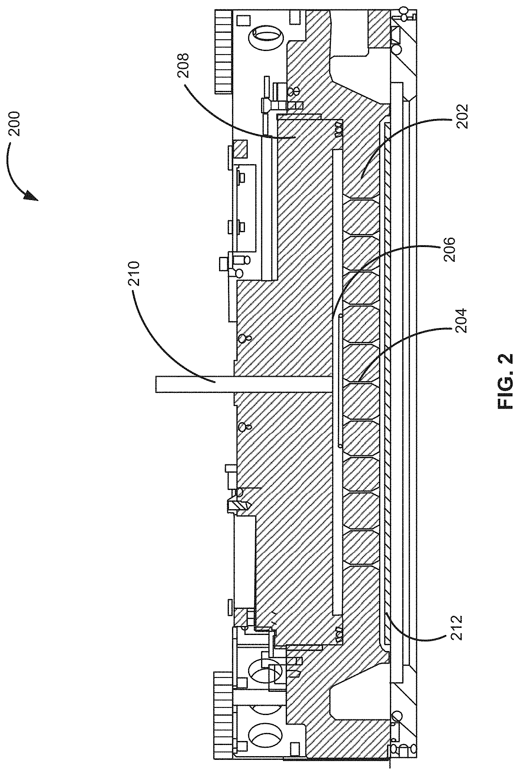
[0014] FIG. 2 illustrates a showerhead assembly in accordance with exemplary embodiments of the disclosure.
[0015] FIGS. 3(a)-3(c) illustrate a distribution plate in accordance with exemplary embodiments of the disclosure.
[0016] FIG. 4 illustrates a cross-sectional view of a distribution plate in accordance with exemplary embodiments of the disclosure.
[0017] FIG. 5 illustrates another cross-sectional view of a distribution plate in accordance with exemplary embodiments of the disclosure.
[0018] FIG. 6 illustrates a plan view of a portion of a distribution plate, illustrating apertures in accordance with exemplary embodiments of the disclosure.
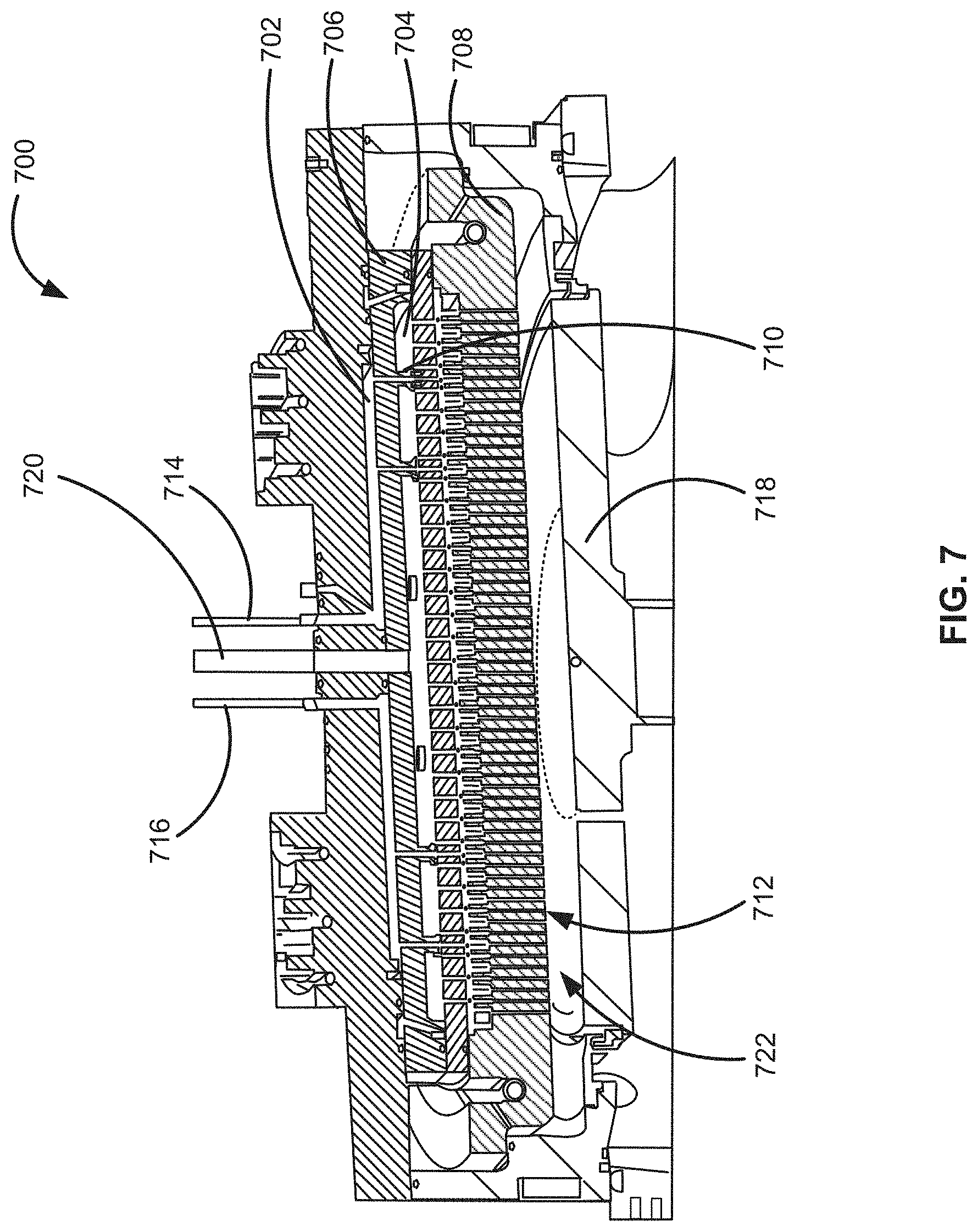
[0019] FIG. 7 illustrates another showerhead assembly in accordance with additional exemplary embodiments of the disclosure.
[0020] It will be appreciated that elements in the figures are illustrated for simplicity and clarity and have not necessarily been drawn to scale. For example, the dimensions of some of the elements in the figures may be exaggerated relative to other elements to help to improve the understanding of illustrated embodiments of the present disclosure.
DETAILED DESCRIPTION OF EXEMPLARY EMBODIMENTS OF THE DISCLOSURE
[0021] The description of exemplary embodiments provided below is merely exemplary and is intended for purposes of illustration only; the following description is not intended to limit the scope of the disclosure or the claims. Moreover, recitation of multiple embodiments having stated features is not intended to exclude other embodiments having additional features or other embodiments incorporating different combinations of the stated features.
[0022] The present disclosure generally relates to gas distribution systems, to showerhead assemblies of gas distribution systems, to distribution plates of gas distribution systems, to reactor systems including the gas distribution systems, and to methods of using the gas distribution systems, showerhead assemblies, distribution plates, and reactor systems. Gas distribution systems, showerhead assemblies, gas distribution plates, and reactor systems as described herein can be used to process substrates, such as semiconductor wafers, in gas-phase reactors, such as chemical vapor deposition (CVD) reactors, including plasma-enhanced CVD (PECVD) reactors, low-pressure CVD (LPCVD) reactors, atomic layer deposition (ALD) reactors, and the like. By way of examples, the assemblies and components described herein can be used in showerhead-type gas-phase reactor systems, in which gasses generally flow in a downward direction from a showerhead and toward a substrate. Such systems are generally cold-wall type reactors, in which a substrate is heated--e.g., via a substrate support or susceptor.
[0023] Typical showerhead assemblies include a gas distribution plate 102, including a plurality of cylindrical apertures 104 formed therein, as illustrated in FIG. 1. During operation of a reactor system that includes distribution plate 102, material deposits onto a surface of distribution plate 102. For example, when a showerhead including distribution plate 102 is used to deposit material onto a substrate, the material can also be deposited onto a surface of the distribution plate.
[0024] Gas distribution plate 102 includes a substantial area (e.g., area 106) between apertures. Area 106 is generally perpendicular to a direction of gas flow exiting gas distribution plate 102. Gas can accumulate and linger on area 106 of gas distribution plate 102 and/or a corresponding area between apertures on a showerhead chamber side of the gas distribution plate. When gas lingers on the showerhead chamber side of gas distribution plate 102, the lingering gas can be relatively difficult to remove, requiring additional purge time, additional vacuum, or the like. Similarly, when the gas lingers on a deposition side of the gas distribution plate, the gas can be relatively difficult to remove, requiring additional purge time and/or vacuum. The additional purge time and/or vacuum requirements increase a cost associated with processing substrates. In addition, in the case of deposition processes, when gas is allowed to reside over area 106 (on the deposition side of distribution plate 102) for an extended period of time, a film 108 that forms on the deposition side of gas distribution plate 102 can become stressed, resulting in blisters 110, that can form particulates that cause defects in a film deposited on a substrate. Furthermore, gas lingering over the surface for an extended period of time can contribute to excessive decomposition for certain precursors, which may lead to undesirable side effects such as particles or poor film quality.
[0025] FIG. 2 illustrates an exemplary showerhead assembly 200 in accordance with exemplary embodiments of the disclosure. Showerhead assembly 200 includes a gas distribution plate 202, including a plurality of apertures 204, and a chamber or region 206. Showerhead assembly 200 can also include a top plate 208 and a gas inlet 210.
[0026] During operation, one or more purge gasses and/or one or more precursors and/or reactants flow through gas inlet 210, to chamber 206, and through apertures 204 toward a substrate 212. In the illustrated example, the direction of the flow of the gas in gas inlet 210 and apertures 204 is substantially vertical--i.e., substantially (e.g., within five degrees of being) perpendicular to a surface of substrate 212. This allows relatively uniform distribution of the gasses across a surface of the substrate.
[0027] Turning now to FIG. 3(a)-FIG. 6, exemplary gas distribution plate 202 is illustrated in greater detail. FIG. 3(a) illustrates a top view or chamber-side view of gas distribution plate 202, FIG. 3(b) illustrates a side view of gas distribution plate 202, FIG. 3(c) illustrates a bottom or deposition-side surface view of gas distribution plate 202, FIG. 4 illustrates a perspective cross-sectional view of gas distribution plate 202, FIG. 5 illustrates a side cross-sectional view of gas distribution plate 202, and FIG. 6 illustrates a partial top view of gas distribution plate 202.
[0028] Gas distribution plate 202 includes a first (chamber-side) surface 302, a second (deposition-side) surface 304, and a plurality of apertures 204, spanning between first surface 302 and second surface 304. Exemplary gas distribution plate also includes a recess 306 to receive a sealing member, such as a gasket (e.g., elastomeric O-ring) to facilitate forming a seal between gas distribution plate 202 and second plate 208, to thereby form chamber 206 adjacent to first surface 302. A thickness of gas distribution plate can be between about 1 mm to 50 mm, about 10 mm to about 40 mm, or about 20 mm to about 30 mm.
[0029] FIGS. 4 and 5 illustrate exemplary apertures 204 in greater detail. Apertures 204 include three sections: a first section 402, a second section 404, and a conduit 406 spanning between first section 402 and second section 404. First section 402 and second section 404 are designed to reduce an amount of surface area on first surface 302 and second surface 304, respectively that is perpendicular to a direction of gas flow toward a substrate (e.g., substrate 212), compared to a typical gas distribution plate. This reduces areas where gas can stagnate. In addition, first section 402 and second section 404 are designed to facilitate gas flow in a direction that is substantially perpendicular to a surface of a substrate. Conduit 406 is configured to provide desired gas flow between chamber 206 and a substrate, while also providing a sufficient pressure differential between first surface 302 and second surface 304 to prevent or mitigate gasses flowing from a reaction chamber to chamber 206. A number of apertures through gas distribution plate can depend on, for example, a size of the distribution plate. Exemplary numbers of apertures on a gas distribution plate range from about 100 to about 1500, about 200 to about 1000, or about 500 to about 900.
[0030] First section 402 includes a first-section first end 502 in contact with first surface 302, a first-section second end 504 in contact with a conduit first end 516, and a first-section tapering wall 506 there between, wherein a cross-sectional area of first-section first end 502 is greater than a cross-sectional area of the first-section second end 504. Tapering wall 506 can be continuously tapering, such as linearly tapering--e.g., frusto-pyramidal or frusto-conical shape, or include a curvature, such as partial spherical or partial ellipsoid. Conduit 406 can include a contract cross-sectional area along an axis. By way of example, conduit 406 can be cylindrical in shape.
[0031] A cross-sectional dimension of first-section first end 502 (e.g., a largest dimension of first end 502 in a direction perpendicular to an axis running through first end 502) can range from about 3 mm to about 30 mm, or about 5 mm to about 20 mm, to about 8 mm to about 10 mm. The cross-sectional dimension of the first-section second end 504 corresponds to a cross-sectional area of conduit 406, which is discussed in more detail below.
[0032] An angle .theta. between opposing sides of tapering wall 506 can range from about 30.degree. to less than 90.degree., about 45.degree. to about 88.degree., about 60.degree. to about 85.degree., or be about 82.degree.. A length of the first section (and/or second section) along an axis can range from about 0.25 mm to about 20 mm, about 1 mm to about 10 mm, or about 3 mm to about 7 mm.
[0033] Similarly, second section 404 includes a second-section first end 508 in contact with second surface 304, a second-section second end 510 fluidly coupled to a conduit (e.g., conduit 406) second end 514, and a second-section tapering wall 512 there between, wherein a cross-sectional area of the second-section first end is greater than a cross-sectional area of the second-section second end. The dimensions and shapes of a second-section first end 508, second-section second end 510, and second-section tapering wall 512 can be the same or similar to the corresponding sections of first section 402. For example, a cross-sectional width of second-section first end 508 can range from about 3 mm to about 30 mm, or about 5 mm to about 20 mm, to about 8 mm to about 10 mm, and the cross-sectional area of the second-section second end 510 corresponds to a cross-sectional area/width of conduit 406. And, an angle .alpha. of opposing sides of tapering wall 512 can range from about 30.degree. to less than 90.degree., about 45.degree. to about 88.degree., about 60.degree. to about 85.degree., or be about 82.degree..
[0034] A ratio of a length of conduit 406 to first and/or second sections can be important to provide desired gas flow patterns and pressure differential between chamber 206 and a reaction chamber. In accordance with exemplary embodiments of the disclosure, a ratio of a length of conduit 406 to first section 402 and/or second section 404 (e.g., along a common axis thereof) is between about 1:1 and about 8:1, about 2:1 to about 7:1, or about 3:1 to about 5:1.
[0035] A length of conduit 406 can range from about 0.5 mm to about 50 mm, about 5 mm to about 40 mm, or about 10 mm to about 30 mm. A dimension (e.g., a diameter) of a conduit can be about 0.1 mm to about 10 mm, 0.25 mm to about 5 mm, or about 0.5 mm to about 1.5 mm. A cross-section of conduit 406 can be circular, square, rectangular, or any suitable shape.
[0036] With reference to FIG. 6, a configuration of apertures 204 can be hexagonal. In this case, adjacent apertures 204 are along a vertical axis 602, and along axes 604, 606, which are 30.degree. from a horizontal axis 608 (or 60.degree. from axis 602). In the illustrated example, a spacing c of adjacent apertures 204 centers along a vertical can be between 2 mm and 20 mm, about 5 mm to about 15 mm, or about 9 mm to about 11 mm. A spacing b of aperture 204 centers can be about 1 mm to about 10 mm, about 2 mm to about 8 mm, or be about 4 mm to about 6 mm. And, a spacing a can be the same or similar to spacing c. A distance between perimeters of adjacent apertures can range from 0 mm to about 10 mm, about 0 mm to about 5 mm, or greater than 0 mm to about 10 mm, or 0.25 mm to about 5 mm.
[0037] FIG. 7 illustrates another showerhead 700 in accordance with further exemplary embodiments of the disclosure. Showerhead 700 is similar to showerhead 200, except showerhead 700 includes a first chamber 702 and a second chamber 704, a first gas distribution plate 706 and a second gas distribution plate 708, and first apertures 710 formed through first gas distribution plate and second apertures 712 formed through second gas distribution plate 708. First apertures 710 and/or second apertures 712 can be the same or similar to apertures 204, described above.
[0038] During use of showerhead 700, a first gas can flow through one or more first inlets 714, 716 to first chamber 702, through apertures 710 and toward a substrate residing on a susceptor 718, and a second gas can flow from a second inlet 720 to second chamber 704, and through apertures 712, such that the first gas and the second gas do not mix until reaching a reaction chamber 722.
[0039] Although exemplary embodiments of the present disclosure are set forth herein, it should be appreciated that the disclosure is not so limited. For example, although the gas distribution assemblies and plates and the reactor systems are described in connection with various specific configurations, the disclosure is not necessarily limited to these examples. Various modifications, variations, and enhancements of the exemplary assemblies, systems, plates, and methods set forth herein may be made without departing from the spirit and scope of the present disclosure.
[0040] The subject matter of the present disclosure includes all novel and nonobvious combinations and subcombinations of the various systems, components, and configurations, and other features, functions, acts, and/or properties disclosed herein, as well as any and all equivalents thereof.
* * * * *
D00000
D00001
D00002
D00003
D00004
D00005
D00006
D00007
XML
uspto.report is an independent third-party trademark research tool that is not affiliated, endorsed, or sponsored by the United States Patent and Trademark Office (USPTO) or any other governmental organization. The information provided by uspto.report is based on publicly available data at the time of writing and is intended for informational purposes only.
While we strive to provide accurate and up-to-date information, we do not guarantee the accuracy, completeness, reliability, or suitability of the information displayed on this site. The use of this site is at your own risk. Any reliance you place on such information is therefore strictly at your own risk.
All official trademark data, including owner information, should be verified by visiting the official USPTO website at www.uspto.gov. This site is not intended to replace professional legal advice and should not be used as a substitute for consulting with a legal professional who is knowledgeable about trademark law.