Method And System For Cold-forming Glass
Cho; Dongyoung ; et al.
U.S. patent application number 16/944685 was filed with the patent office on 2021-02-04 for method and system for cold-forming glass. The applicant listed for this patent is CORNING INCORPORATED. Invention is credited to Dongyoung Cho, Hyun-Soo Choi, Ki-Nam Kim, Shin Kim.
| Application Number | 20210032150 16/944685 |
| Document ID | / |
| Family ID | 1000005021020 |
| Filed Date | 2021-02-04 |
| United States Patent Application | 20210032150 |
| Kind Code | A1 |
| Cho; Dongyoung ; et al. | February 4, 2021 |
METHOD AND SYSTEM FOR COLD-FORMING GLASS
Abstract
Disclosed are embodiments of a method of forming a curved glass article. In the method, a mold having a curved surface is provided. A self-adhesive layer is disposed on the curved surface. A glass sheet is bent into conformity with the curved surface at a temperature less than the glass transition temperature of the glass sheet. The glass sheet includes a first major surface and a second major surface in which the second major surface is opposite to the first major surface. The first major surface is adhered to the self-adhesive layer. A frame is bonded to the second major surface of the glass sheet, and the glass sheet is removed from the self-adhesive layer. A system for performing the method and a mold having a self-adhesive layer are also disclosed.
| Inventors: | Cho; Dongyoung; (Cheongju-si, KR) ; Choi; Hyun-Soo; (Cheonan-si, KR) ; Kim; Ki-Nam; (Cheonan City, KR) ; Kim; Shin; (Seocho-gu, KR) | ||||||||||
| Applicant: |
|
||||||||||
|---|---|---|---|---|---|---|---|---|---|---|---|
| Family ID: | 1000005021020 | ||||||||||
| Appl. No.: | 16/944685 | ||||||||||
| Filed: | July 31, 2020 |
Related U.S. Patent Documents
| Application Number | Filing Date | Patent Number | ||
|---|---|---|---|---|
| 62880820 | Jul 31, 2019 | |||
| Current U.S. Class: | 1/1 |
| Current CPC Class: | C03B 23/0357 20130101 |
| International Class: | C03B 23/035 20060101 C03B023/035 |
Claims
1. A method of forming a curved glass article, comprising: bending a glass sheet at a temperature less than the glass transition temperature of the glass sheet to confirm with a curved surface of a mold comprising a self-adhesive layer disposed on the curved surface, wherein the glass sheet comprises a first major surface and a second major surface, wherein the second major surface is opposite to the first major surface, and wherein the first major surface is adhered to the self-adhesive layer; bonding a frame to the second major surface of the glass sheet; removing the glass sheet from the self-adhesive layer.
2. The method of claim 1, wherein bonding further comprising applying an adhesive to the frame or to the second major surface of the glass sheet, positioning the frame on the second major surface, and curing the adhesive.
3. The method of claim 2, wherein the adhesive comprises at least one of a toughened adhesive, a flexible epoxy, an acrylic, a urethane, or a silicone.
4. The method of claim 1, wherein the self-adhesive layer comprises at least one of a polyurethane, a silicone, an acrylic, a polyester, a polyolefin, a polyacrylamide, or a polyether-urethane copolymer.
5. The method of claim 1, wherein the curved surface comprises at least one of a convex curvature, a concave curvature, and both a convex curvature and a concave curvature.
6. The method of claim 1, wherein the curved surface has a radius of curvature of from 30 mm to 5 m.
7. The method of claim 1, wherein bending takes place at a temperature of less than 200.degree. C.
8. The method of claim 1, wherein the glass sheet has a thickness between the first major surface and the second major surface of from 0.4 mm to 2.0 mm.
9. The method of claim 1, further comprising bonding a display to the second major surface using optically clear adhesive.
10. The method of claim 12, wherein the display comprises at least one of a light-emitting diode display, an organic light-emitting diode display, a plasma display, or a liquid crystal display.
11. The method of claim 1, wherein the first major surface and the second major surface are chemically strengthened.
12. A system for cold-forming curved glass articles, comprising: a conveyor system; a plurality of molds arranged on the conveyor system, each of the plurality of molds comprising a curved surface and a self-adhesive layer; wherein the conveyer system is configured such that at a first position on the conveyor system, a first major surface of a glass sheet is adhered to the self-adhesive layer of one mold of the first plurality of molds; at a second position on the conveyor system, a frame is positioned on and adhered to a second major surface of the glass sheet, wherein the second major surface is opposite to the first major surface; at a final position on the conveyor system, the glass sheet with bonded frame is removed from the mold; and between the second position and the final position, the self-adhesive layer is cured.
13. The system of claim 18, wherein the self-adhesive layer comprises a polyurethane, a silicone, an acrylic, a polyester, a polyolefin, a polyacrylamide, or a polyether-urethane copolymer.
14. The system of claim 12, wherein the curved surface comprises a convex curvature, a concave curvature, and both a convex curvature and a concave curvature.
15. The system of claim 12, wherein the curved surface has a radius of curvature of from 30 mm to 5 m.
16. The system of claim 12, wherein the system is operated at a temperature of less than 200.degree. C.
17. The system of claim 12, further comprising a vacuum system configured to apply a negative pressure to the glass sheet adhered to the self-adhesive layer through a plurality of vacuum channels formed into at least one of the plurality of molds.
18. The system of claim 17, wherein the vacuum system is also configured to apply a positive pressure to the glass sheet to facilitate releasing the glass sheet from the self-adhesive layer at the final position.
19. A mold for forming a curved glass article, the mold comprising: a curved surface comprising at least one of a convex curvature or a concave curvature; a self-adhesive layer disposed on the curved surface; wherein the self-adhesive layer comprises a polyurethane, a silicone, an acrylic, a polyester, a polyolefin, a polyacrylamide, or a polyether-urethane copolymer.
20. The mold of claim 19, wherein the curved surface has a radius of curvature of from 30 mm to 5 m and wherein the self-adhesive layer has an adhesion force of from 1 kgf/cm.sup.2 to 10 kgf/cm.sup.2.
Description
CROSS-REFERENCE TO RELATED APPLICATIONS
[0001] This application claims the benefit of priority under 35 U.S.C. .sctn. 119 of U.S. Provisional Application Ser. No. 62/880,820 filed on Jul. 31, 2019 the content of which is relied upon and incorporated herein by reference in its entirety.
BACKGROUND
[0002] The disclosure relates to vehicle interior systems including glass and methods for forming the same, and more particularly to vehicle interior systems including a curved glass article with a cold-formed or cold-bent cover glass and methods for forming the same.
[0003] Vehicle interiors include curved surfaces and can incorporate displays in such curved surfaces. The materials used to form such curved surfaces are typically limited to polymers, which do not exhibit the durability and optical performance as glass. As such, curved glass sheets are desirable, especially when used as covers for displays. Existing methods of forming such curved glass sheets, such as thermal forming, have drawbacks including high cost, optical distortion, and surface marking. Accordingly, Applicant has identified a need for vehicle interior systems that can incorporate a curved glass sheet in a cost-effective manner and without problems typically associated with glass thermal forming processes.
SUMMARY
[0004] According to an aspect, embodiments of the disclosure relate to a method of forming a curved glass article. In the method, a mold having a curved surface is provided. A self-adhesive layer is disposed on the curved surface. A glass sheet is bent into conformity with the curved surface at a temperature less than the glass transition temperature of the glass sheet. The glass sheet includes a first major surface and a second major surface in which the second major surface is opposite to the first major surface. The first major surface is adhered to the self-adhesive layer. A frame is bonded to the second major surface of the glass sheet, and the glass sheet is removed from the self-adhesive layer.
[0005] According to another aspect, embodiments of the disclosure relate to a system for cold-forming curved glass articles. The system includes a conveyor system, and a plurality of molds arranged on the conveyor system. Each of the plurality of molds comprising a curved surface and a self-adhesive layer. At a first position on the conveyor system, a first major surface of a glass sheet is adhered to the self-adhesive layer of one mold of the first plurality of molds. At a second position on the conveyor system, a frame is positioned on and adhered to a second major surface of the glass sheet. The second major surface is opposite to the first major surface. At a final position on the conveyor system, the glass sheet with bonded frame is removed from the mold. Between the second position and the final position, the conveyor system has a length and speed configured to allow curing of the frame adhered to the glass sheet.
[0006] According to still another aspect, embodiments of the disclosure relate to a mold for forming a curved glass article. The mold includes a curved surface and a self-adhesive layer disposed on the curved surface. The self-adhesive layer comprises at least one of a polyurethane, a silicone, an acrylic, a polyester, a polyolefin, a polyacrylamide, or a polyether-urethane copolymer. Further, the curved surface comprises at least one of a convex curvature or a concave curvature.
[0007] Additional features and advantages will be set forth in the detailed description which follows, and in part will be readily apparent to those skilled in the art from that description or recognized by practicing the embodiments as described herein, including the detailed description which follows, the claims, as well as the appended drawings.
[0008] It is to be understood that both the foregoing general description and the following detailed description are merely exemplary, and are intended to provide an overview or framework to understanding the nature and character of the claims. The accompanying drawings are included to provide a further understanding, and are incorporated in and constitute a part of this specification. The drawings illustrate one or more embodiment(s), and together with the description serve to explain principles and operation of the various embodiments.
BRIEF DESCRIPTION OF THE DRAWINGS
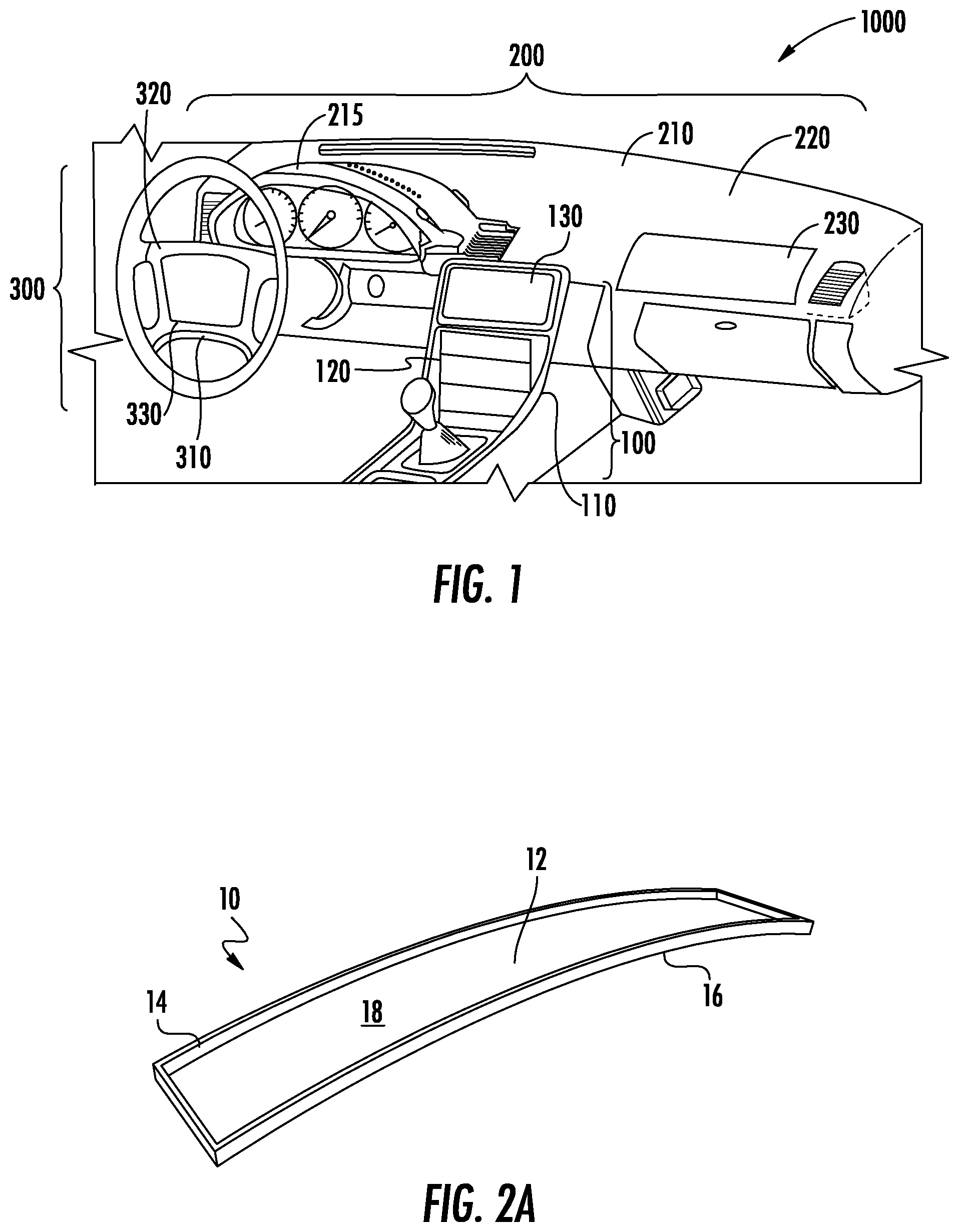
[0009] FIG. 1 is a perspective view of a vehicle interior with vehicle interior systems, according to exemplary embodiments.
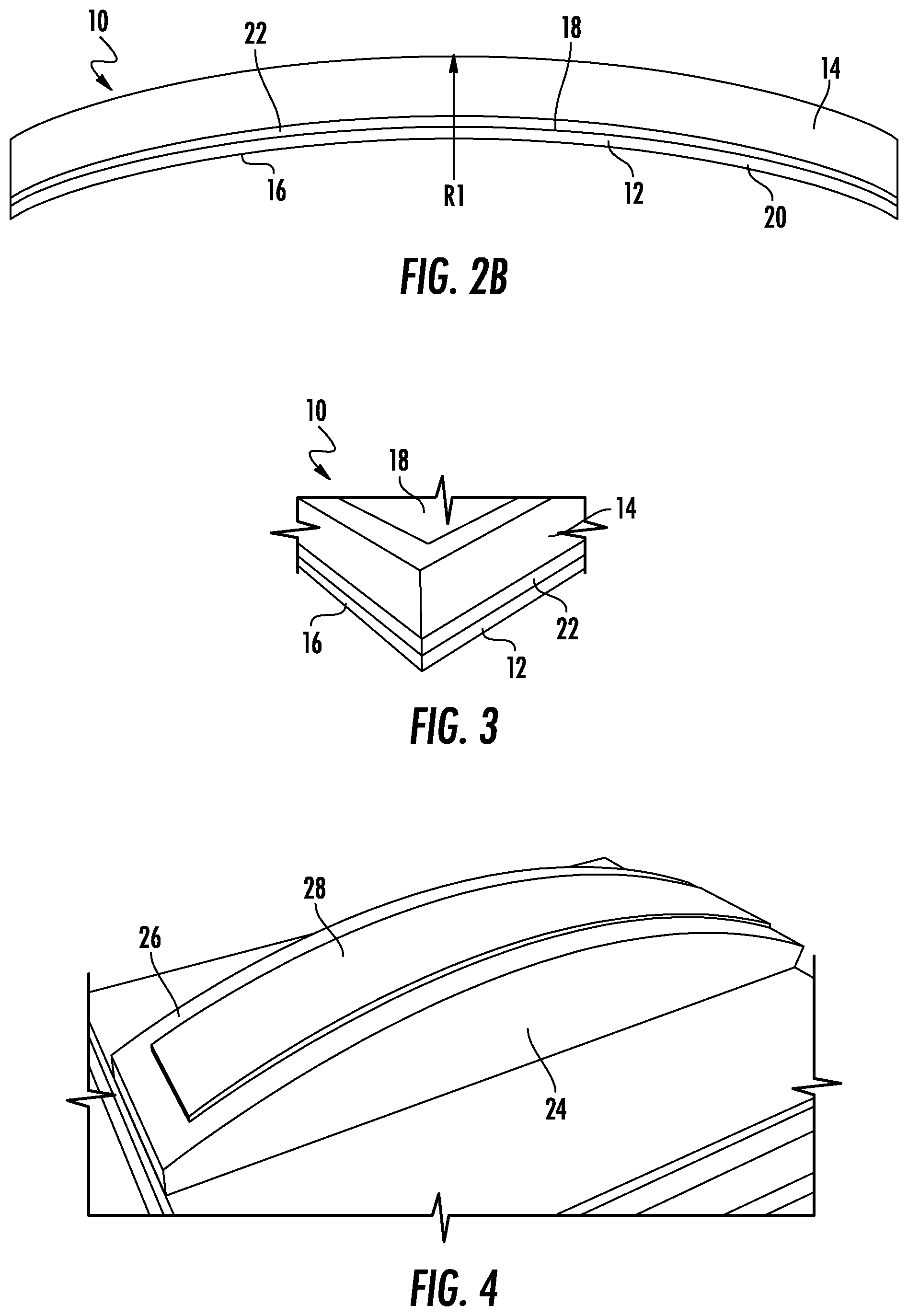
[0010] FIGS. 2A and 2B depict a curved glass article, according to an exemplary embodiment.
[0011] FIG. 3 depicts a close-up view of a corner of the curved glass article of FIG. 2A, according to an exemplary embodiment.
[0012] FIG. 4 depicts a mold with a self-adhesive layer for cold-forming a curved glass article, according to an exemplary embodiment.
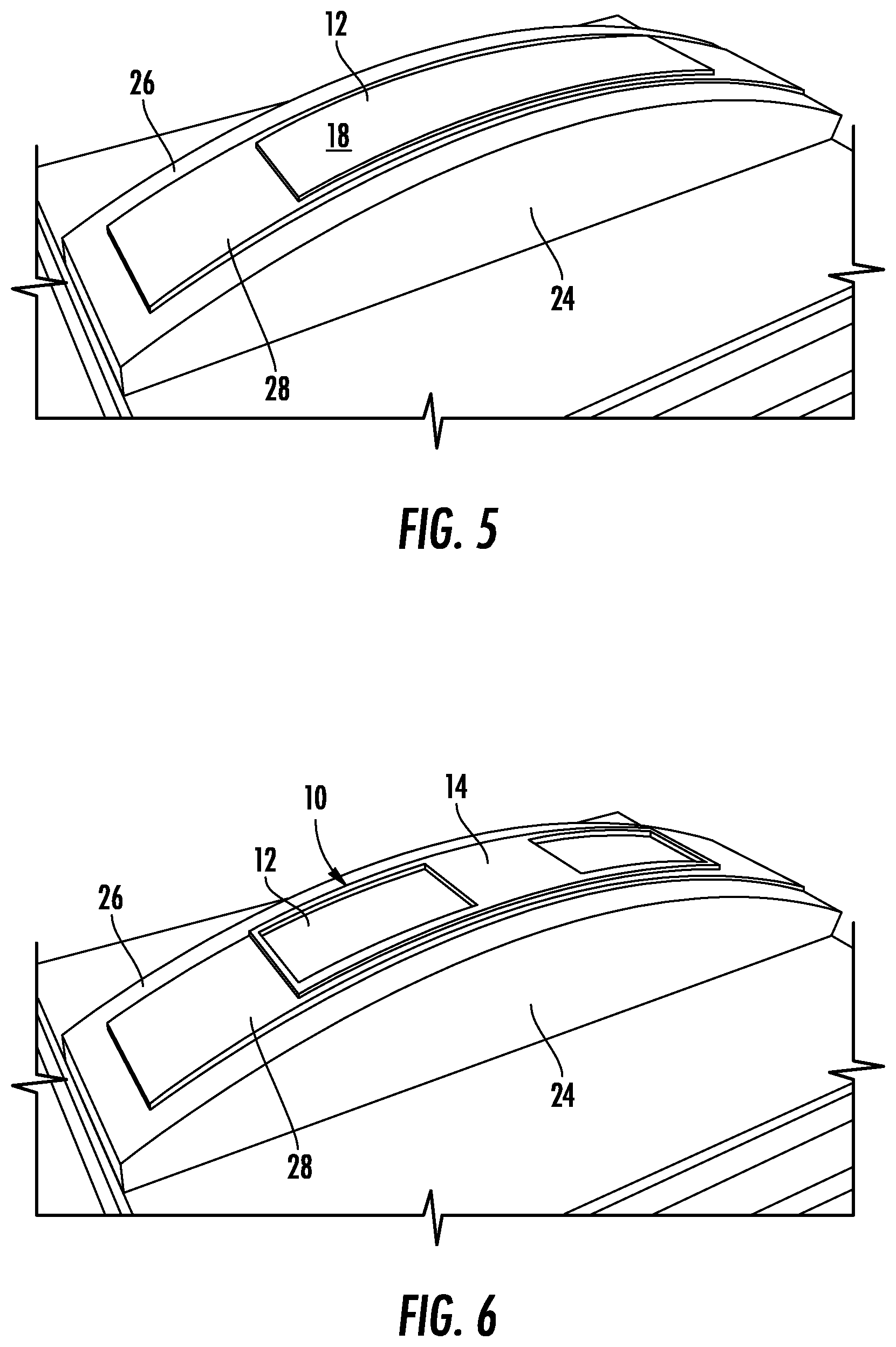
[0013] FIG. 5 depicts the mold of FIG. 4 with a glass sheet thereon, according to an exemplary embodiment.
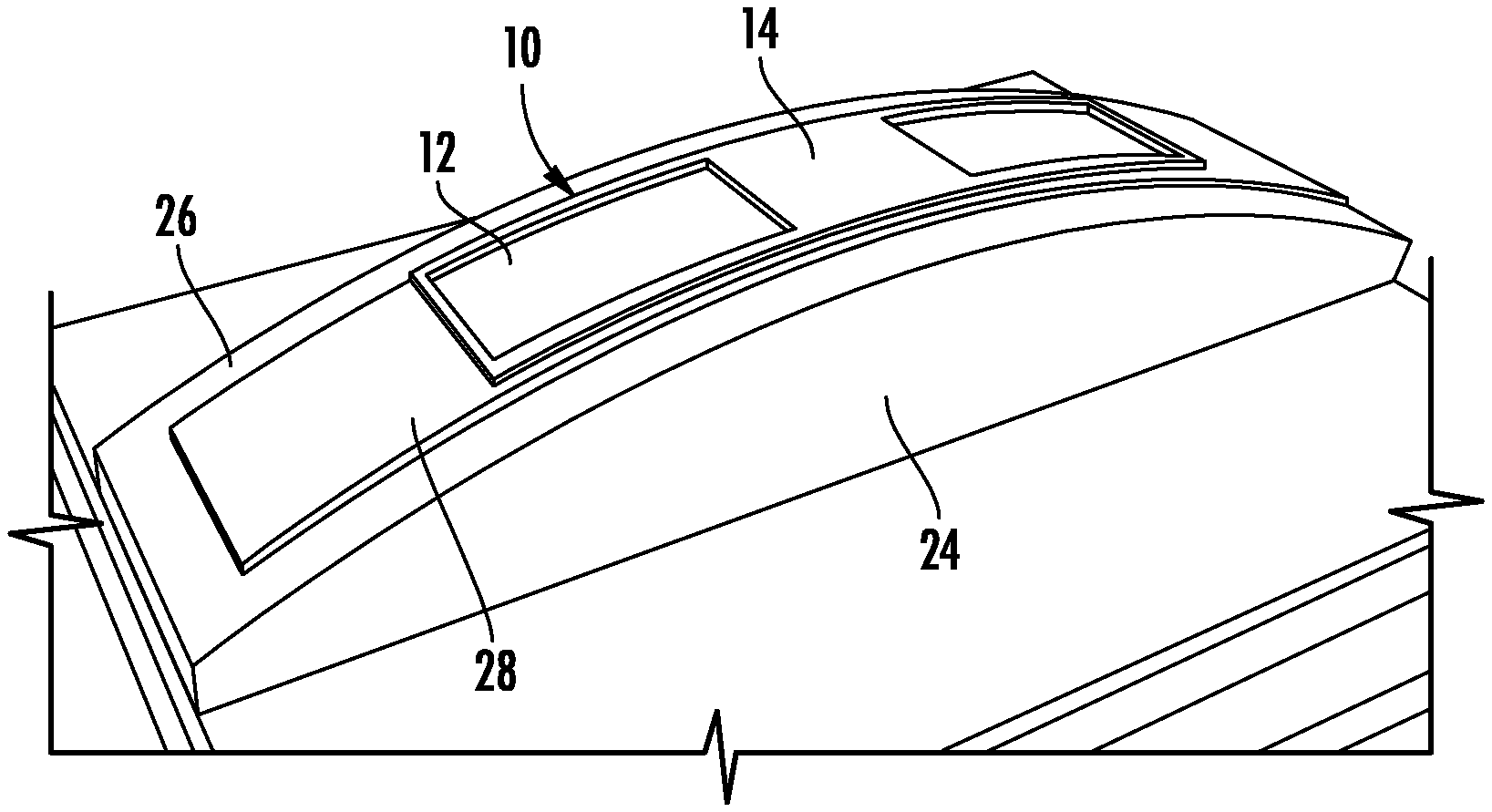
[0014] FIG. 6 depicts the mold of FIG. 4 with a glass sheet and frame thereon, according to an exemplary embodiment.
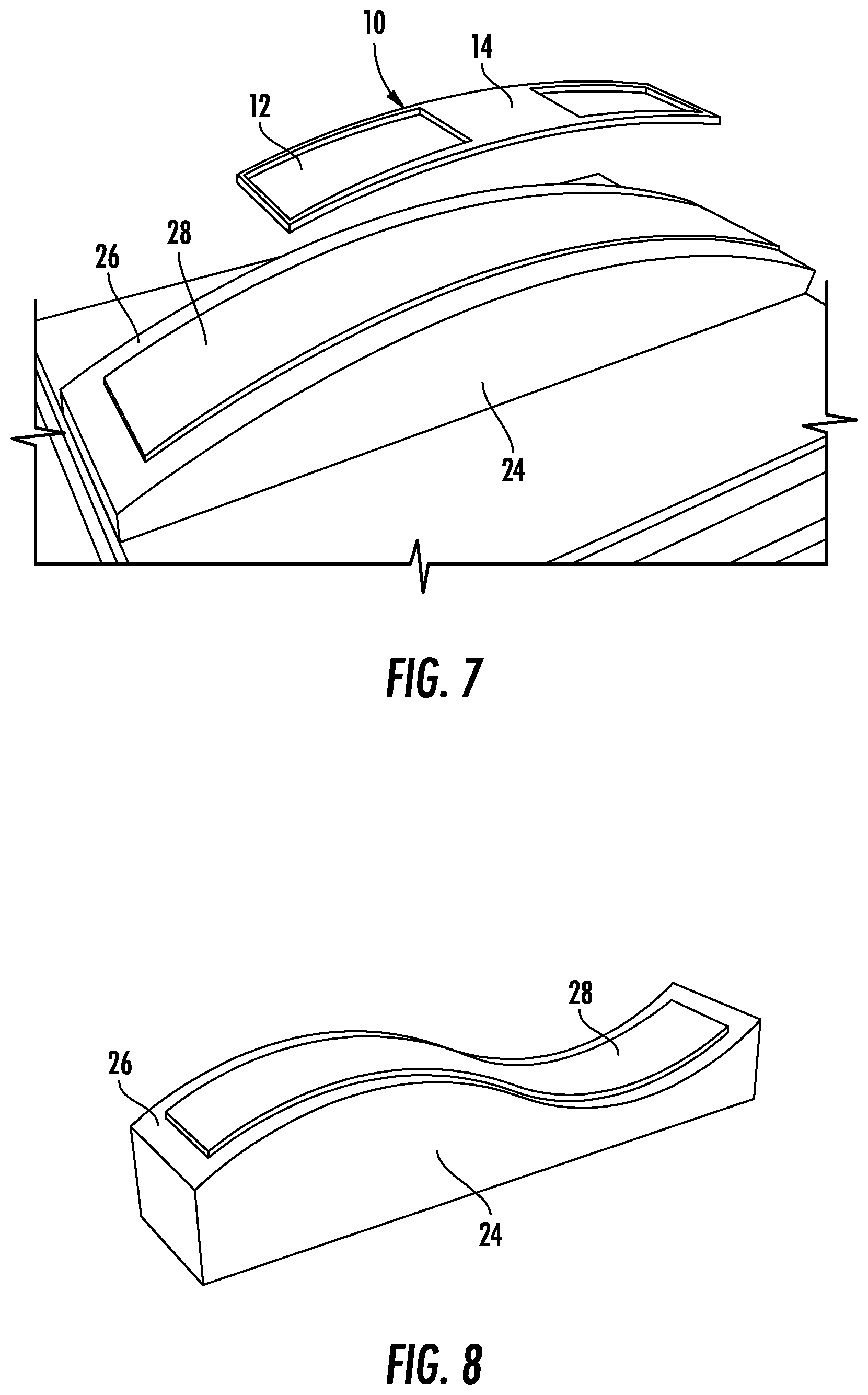
[0015] FIG. 7 depicts the mold of FIG. 4 with a curved glass article being released from the self-adhesive layer after the adhesive bonding the frame to the glass sheet has cured, according to an exemplary embodiment.
[0016] FIGS. 8 and 9 depict embodiments of molds having curvatures different from the mold shown in FIG. 4, according to exemplary embodiments.
[0017] FIG. 10 depicts another embodiment of a mold having vacuum channels, according to an exemplary embodiment.
[0018] FIG. 11 depicts a system for cold-forming a glass sheet, according to an exemplary embodiment.
[0019] FIG. 12 depicts a glass sheet with exemplary dimensions, according to an exemplary embodiment.
DETAILED DESCRIPTION
[0020] Reference will now be made in detail to various embodiments, examples of which are illustrated in the accompanying drawings. In general, a vehicle interior system may include a variety of different curved surfaces that are designed to be transparent, such as curved display surfaces and curved non-display glass covers, and the present disclosure provides articles and methods for forming these curved surfaces from a glass material. Forming curved vehicle surfaces from a glass material provide a number of advantages compared to the typical curved plastic panels that are conventionally found in vehicle interiors. For example, glass is typically considered to provide enhanced functionality and user experience in many curved cover material applications, such as display applications and touch screen applications, compared to plastic cover materials.
[0021] Accordingly, as will be discussed in more detail below, Applicant has developed a glass article and related manufacturing processes that provide an efficient and cost effective way to form an article, such as a display for a vehicle interior system, utilizing a cold-bent glass sheet.
[0022] In particular embodiments, the curved glass article is formed by adhering a glass sheet to a curved mold using a self-adhesive layer. Thereafter, an adhesive is applied to either the bent glass sheet while on the mold or to the frame, and a frame is adhered to the bent glass sheet. The adhesive is allowed to cure while the glass is on the mold to bond the frame to the glass sheet to form the curved glass article. The curved glass article can be removed from the self-adhesive layer, and the mold can be reused for another molding process. In embodiments, a system for molding glass articles is provided. In the system, a plurality of molds is provided, which allows for multiple glass articles to be made and cured at the same time. In embodiments of the system, the actions of adhering the glass sheet to the mold and removing the glass article from the mold can be automated, e.g., the actions can be performed by robots while moving the plurality of molds around a conveyor system. Various aspects and advantages of the curved glass article and method of forming same will be described in relation to the exemplary embodiments described herein and shown in the figures.
[0023] FIG. 1 shows an exemplary vehicle interior 1000 that includes three different embodiments of a vehicle interior system 100, 200, 300. Vehicle interior system 100 includes a frame, shown as center console base 110, with a curved surface 120 including a curved display 130. Vehicle interior system 200 includes a frame, shown as dashboard base 210, with a curved surface 220 including a curved display 230. The dashboard base 210 typically includes an instrument panel 215 which may also include a curved display. Vehicle interior system 300 includes a frame, shown as steering wheelbase 310, with a curved surface 320 and a curved display 330. In one or more embodiments, the vehicle interior system includes a frame that is an arm rest, a pillar, a seat back, a floorboard, a headrest, a door panel, or any portion of the interior of a vehicle that includes a curved surface. In other embodiments, the frame is a portion of a housing for a free-standing display (i.e., a display that is not permanently connected to a portion of the vehicle). In embodiments, the display 130, 230, 330 may be at least one of a light-emitting diode display, an organic light-emitting diode display, a plasma display, or a liquid crystal display bonded to a rear surface (e.g., using an optically clear adhesive) of a curved glass article 10 disclosed herein.
[0024] The embodiments of the curved glass article described herein can be used in each of vehicle interior systems 100, 200 and 300. Further, the curved glass articles discussed herein may be used as curved cover glasses for any of the curved display embodiments discussed herein, including for use in vehicle interior systems 100, 200 and/or 300. Further, in various embodiments, various non-display components of vehicle interior systems 100, 200 and 300 may be formed from the glass articles discussed herein. In some such embodiments, the glass articles discussed herein may be used as the non-display cover surface for the dashboard, center console, door panel, etc. In such embodiments, glass material may be selected based on its weight, aesthetic appearance, etc. and may be provided with a coating (e.g., an ink or pigment coating) with a pattern (e.g., a brushed metal appearance, a wood grain appearance, a leather appearance, a colored appearance, etc.) to visually match the glass components with adjacent non-glass components. In specific embodiments, such ink or pigment coating may have a transparency level that provides for deadfront functionality.
[0025] FIG. 2A depicts a curved glass article 10, such as the cover glass for curved display 130, 230, 330 according to exemplary embodiments. It should be understood that, while FIG. 2A is described in terms of forming curved display 130, 230, 330, the curved glass article 10 of FIG. 2A may be used in any suitable curved glass application, including any curved glass component of any of the vehicle interior systems of FIG. 1 or other curved glass surfaces of the vehicle interior 1000. Such curved glass components could be display or non-display regions, e.g., a flat display area and a curved non-display area, curved displays, and curved display and curved non-display areas.
[0026] As shown in FIG. 2A, the curved glass article 10 includes a glass sheet 12 and a frame 14. The frame 14 holds the glass sheet 12 in a curved configuration. As shown in the side view of FIG. 2B, the glass sheet 12 includes a first major surface 16 and a second major surface 18 opposite first major surface 16. In embodiments, the second major surface 18 is a rear surface of the A minor surface 20 connects the first major surface 16 and the second major surface 18, and in specific embodiments, minor surface 20 defines the outer perimeter of glass sheet 12. The glass sheet 12 is attached to the frame 14 via an adhesive layer 22. As shown in the close-up view of FIG. 3, in embodiments, the adhesive layer 22 is applied only where the frame 14 is attached to the glass sheet 12.
[0027] The adhesive layer 22 provides long term strength after curing over the course of, e.g., about an hour at ambient temperature. In embodiments, exemplary adhesives for the adhesive layer 22 include toughened epoxy, flexible epoxy, acrylics, silicones, urethanes, polyurethanes, and silane modified polymers. In specific embodiments, the adhesive layer 22 includes one or more toughened epoxies, such as EP21TDCHT-LO (available from Masterbond.RTM., Hackensack, N.J.), 3M.TM. Scotch-Weld.TM. Epoxy DP460 Off-White (available from 3M, St. Paul, Minn.). In other embodiments, the adhesive layer 22 includes one or more flexible epoxies, such as Masterbond EP21TDC-2LO (available from Masterbond.RTM., Hackensack, N.J.), 3M.TM. Scotch-Weld.TM. Epoxy 2216 B/A Gray (available from 3M, St. Paul, Minn.), and 3M.TM. Scotch-Weld.TM. Epoxy DP125. In still other embodiments, the adhesive layer 22 includes one or more acrylics, such as LORD.RTM. Adhesive 410/Accelerator 19 w/LORD.RTM. AP 134 primer, LORD.RTM. Adhesive 852/LORD.RTM. Accelerator 25 GB (both being available from LORD Corporation, Cary, N.C.), DELO PUR SJ9356 (available from DELO Industrial Adhesives, Windach, Germany), Loctite.RTM. AA4800, Loctite.RTM. HF8000. TEROSON.RTM. MS 9399, and TEROSON.RTM. MS 647-2C (these latter four being available from Henkel AG & Co. KGaA, Dusseldorf, Germany), among others. In yet other embodiments, the adhesive layer 22 includes one or more urethanes, such as 3M.TM. Scotch-Weld.TM. Urethane DP640 Brown and 3M.TM. Scotch-Weld.TM. Urethane DP604, and in still further embodiments, the adhesive layer 22 includes one or more silicones, such as Dow Corning.RTM. 995 (available from Dow Corning Corporation, Midland, Mich.).
[0028] Returning to FIG. 2B, the glass sheet 12 has a curved shape such that first major surface 16 and second major surface 18 each include at least one curved section having a radius of curvature R1. In embodiments, R1 is between 30 mm and 5 m. Further, in embodiments, the glass sheet 12 has a thickness T1 (e.g., an average thickness measured between surfaces 16, 18) shown in FIG. 2B that is in a range from 0.05 mm to 2 mm. In specific embodiments, T1 is less than or equal to 1.5 mm and in more specific embodiments, T1 is 0.4 mm to 1.3 mm. Applicant has found that such thin glass sheets can be cold formed to a variety of curved shapes (including the relatively high curvature radii of curvature discussed herein) utilizing cold forming without breakage while at the same time providing for a high quality cover layer for a variety of vehicle interior applications. In addition, such thin glass sheets 12 may deform more readily, which could potentially compensate for shape mismatches and gaps that may exist relative to the frame 14.
[0029] In various embodiments, first major surface 16 and/or the second major surface 18 of glass sheet 12 includes one or more surface treatments or layers. The surface treatment may cover at least a portion of the first major surface 16 and/or second major surface 18. Exemplary surface treatments include anti-glare surfaces/coatings, anti-reflective surfaces/coatings, and an easy-to-clean surface coating/treatment. In one or more embodiments, at least a portion of the first major surface 16 and/or the second major surface 18 may include any one, any two or all three of an anti-glare surface, an anti-reflective surface, and easy-to-clean coating/treatment. For example, first major surface 16 may include an anti-glare surface and second major surface 18 may include an anti-reflective surface. In another example, first major surface 16 includes an anti-reflective surface and second major surface 18 includes an anti-glare surface. In yet another example, the first major surface 16 comprises either one of or both the anti-glare surface and the anti-reflective surface, and the second major surface 18 includes the easy-to-clean coating.
[0030] In embodiments, the glass sheet 12 may also include a pigment design on the first major surface 16 and/or second major surface 18. The pigment design may include any aesthetic design formed from a pigment (e.g., ink, paint and the like) and can include a wood-grain design, a brushed metal design, a graphic design, a portrait, or a logo. The pigment design may be printed onto the glass sheet. In one or more embodiments, the anti-glare surface includes an etched surface. In one or more embodiments, the anti-reflective surface includes a multi-layer coating.
[0031] In general, glass sheet 12 is cold formed or cold bent to the desired curved shape via application of a bending force to the glass sheet 12 while it is situated on a mold 24 as shown in FIG. 4. Advantageously, it is easier to apply surface treatments to a flat glass sheet 12 prior to creating the curvature in the glass sheet 12, and cold-forming allows the treated glass sheet 12 to be bent without destroying the surface treatment (as compared to the tendency of high temperatures associated with hot-forming to destroy surface treatments, which requires surface treatments to be applied to the curved article in a more complicated process). In embodiments, the cold forming process is performed at a temperature less than the glass transition temperature of the glass sheet 12. In particular, the cold forming process may be performed at room temperature (e.g., about 20.degree. C.) or a slightly elevated temperature, e.g., at 200.degree. C. or less, 150.degree. C. or less, 100.degree. C. or less, or at 50.degree. C. or less.
[0032] The mold 24 includes a curved surface 26 on which a self-adhesive layer 28 is disposed. In embodiments, the self-adhesive layer 28 comprises integral surface layers having permanently tacky, pressure sensitive adhesive properties. In embodiments, the self-adhesive layer 28 provides an adhesive force via a surface interaction with the glass sheet 12 (e.g., Van der Waals force, suction force, etc.). Further, in embodiments, the adhesive force is between about 1 kgf/cm.sup.2 and 10 kgf/cm.sup.2, particularly about 5 kgf/cm.sup.2. The adhesive layer 28 is configured to hold the glass sheet 12 in a bent configuration on the mold 24 such that the glass sheet 12 matches the curvature of the curved surface 26 of the mold. In particular, the first major surface 16 of the glass sheet 12 is adhered to the self-adhesive layer 28 as shown in FIG. 5.
[0033] In embodiments, the self-adhesive layer 28 comprises at least one of a polyurethane, a silicone, an acrylic, a polyester, a polyolefin, a polyacrylamide, or a polyether-urethane copolymer, among others. In embodiments, the integral surface layers having the tacky, pressure-sensitive adhesive properties may be formed by inhibiting cross-linking on the surface of the self-adhesive layer 28. Advantageously, glass sheets 12 can be repeatedly attached and detached from the self-adhesive layer 28, e.g., to cold-form multiple glass sheets 12 and frames 14 in succession. Further, in embodiments, the surface of the self-adhesive layer 28 can be cleaned and restored to its original state after becoming contaminated with, e.g., oil, dirt, or other debris by washing it with soapy water, acetone, or other suitable cleaning agents. In testing, certain embodiments of the self-adhesive layer 28 have not experienced any change in adhesion force after 33,000 uses, and in embodiments, the self-adhesive layer may be used for months at a time before needing replacement. However, the usable life of the self-adhesive layer may be dictated by a variety of factors, including working environment, cleanliness of the glass/mold, scratches or abrasions from surrounding machinery, etc. Also, advantageously, the self-adhesive layer 28 is strong enough to hold the glass sheet 12 in a bent configuration, but the glass sheet 12 can still be removed from the adhesive layer 28 when it is desired to remove the glass article 10 from the mold.
[0034] As shown in FIG. 6, the frame 14 is adhered to the second major surface 18 of the glass sheet 12. For example, in embodiments, the frame 14 may be coated with the adhesive layer 22 and then attached to the second major surface 18 of the glass sheet. Alternatively or additionally, in embodiments, the second major surface 18 is covered at least partially with the adhesive layer 22 for attaching the frame 14 to the glass sheet 12. After the frame 14 is adhered to the glass sheet 12, the glass article 10 may be allowed to cure on the mold 24 as necessary. Thereafter, the curved glass article 10 is released from the adhesive layer 28.
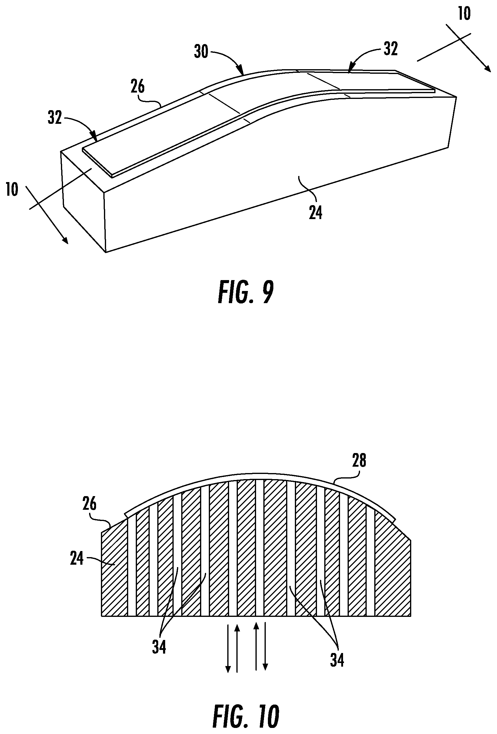
[0035] As can be seen in FIG. 7, the curved surface 26 of the mold 24 provides the glass article 10 with a convex curvature with respect to the first major surface 16. However, in other embodiments, the curved surface 26 of the mold 24 provides the glass sheet 12 with a concave curvature. In other embodiments, such as shown in FIG. 8, the mold 24 has a curved surface 26 that provides the glass sheet 12 with both a concave and a convex curvature. FIG. 9 depicts another embodiment of a mold 24 providing a V-shaped curved glass article 10. In particular, the curved surface 26 of the mold 24 has a curved section 30 and two flat sections 32. Thus, as opposed to the embodiments of the molds 24 shown in FIGS. 4-7 and FIG. 8 that have continuous curvatures, the mold 24 of FIG. 9 is only curved in the curved section 30, which is positioned between two flat sections 32.
[0036] In the embodiment shown in FIG. 10, the mold 24 includes channels 34 through which air between the glass sheet 12 and the self-adhesive layer 28 can be evacuated by application of a negative pressure. That is, in such embodiments, the mold 24 utilizes both an adhesive layer 28 and vacuum pressure to hold the glass sheet 12 in conformity with the curved surface 26. In such embodiments, the channels 34 can also be used to help release the glass article 10 from the mold 24 by blowing air (or another fluid) towards the first major surface 16 of the glass sheet 12 to provide pressure pushing the glass sheet 12 away from the mold 24.
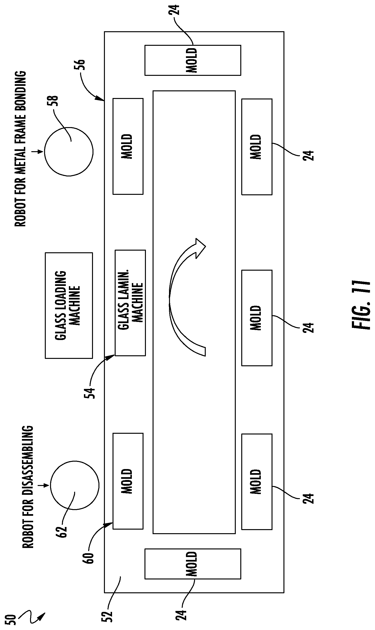
[0037] FIG. 11 schematically depicts an automated system 50 for cold-forming a plurality of curved glass articles 10. In the embodiment shown in FIG. 11, a plurality of molds 24 are provided on a conveyor system 52. At a first position 54, one of the plurality of molds 24 is laminated with a glass sheet 12. In embodiments, the glass sheets 12 may be stored in a glass loading machine that loads glass sheets 12 into a glass laminating machine that bends the glass sheet 12 over a self-adhesive layer 28 of a mold 24. At a second position 56, the frame 14 is bonded to the glass sheet 12. In embodiments, a robotic arm 58 can be used to position the frame 14 over the glass sheet 12, apply adhesive 22 to the glass sheet 12, and/or press the frame 14 onto the glass sheet 12. After the second position 56, the conveyor system 52 moves the molds 24 over a distance for a time sufficient to allow the adhesive layer 22 to cure, bonding the frame 14 to the glass sheet 12. In embodiments, the glass sheet 12 and frame 14 are allowed to cure on the mold 24 for a time of up to one hour. In embodiments, the adhesive layer 22 only bonds to an initial green strength on the conveyor system 52, instead of to a full cure strength, while on the conveyor system 52. The conveyor system 52 moves the molds 24 to a final position 60 where the curved glass article 10 is removed from the mold 24. In an embodiment, the curved glass article 10 is removed from the mold 24 with another robotic arm 62. In embodiments, a pin or diaphragm with air is used to push the curved glass article 10 from the mold 24. The mold 24 is then moved back to the first position 54 where another glass sheet 12 can be laminated to the mold 24, and the mold 54 cycles back around the conveyor system 52.
[0038] In various embodiments, glass sheet 12 is formed from a strengthened glass sheet (e.g., a thermally strengthened glass material, a chemically strengthened glass sheet, etc.) In such embodiments, when glass sheet 12 is formed from a strengthened glass material, first major surface 16 and second major surface 18 are under compressive stress, and thus second major surface 18 can experience greater tensile stress during bending to the convex shape without risking fracture. This allows for strengthened glass sheet 12 to conform to more tightly curved surfaces.
[0039] A feature of a cold-formed glass sheet 12 is an asymmetric surface compressive between the first major surface 16 and the second major surface 18 once the glass sheet 12 has been bent to the curved shape. In such embodiments, prior to the cold-forming process or being cold-formed, the respective compressive stresses in the first major surface 16 and the second major surface 18 of glass sheet 12 are substantially equal. After cold-forming, the compressive stress on concave first major surface 16 increases such that the compressive stress on the first major surface 16 is greater after cold-forming than before cold-forming. In contrast, convex second major surface 18 experiences tensile stresses during bending causing a net decrease in surface compressive stress on the second major surface 18, such that the compressive stress in the second major surface 18 following bending is less than the compressive stress in the second major surface 18 when the glass sheet is flat.
[0040] As noted above, in addition to providing processing advantages such as eliminating expensive and/or slow heating steps, the cold-forming processes discussed herein are believed to generate curved glass articles with a variety of properties that are superior to hot-formed glass articles, particularly for vehicle interior or display cover glass applications. For example, Applicant believes that, for at least some glass materials, heating during hot-forming processes decreases optical properties of curved glass sheets, and thus, the curved glass sheets formed utilizing the cold-bending processes/systems discussed herein provide for both curved glass shapes along with improved optical qualities not believed achievable with hot-bending processes.
[0041] Further, many glass surface treatments (e.g., anti-glare coatings, anti-reflective coatings, easy-to-clean coating, etc.) are applied via deposition processes, such as sputtering processes that are typically ill-suited for coating curved glass articles. In addition, many surface treatments (e.g., anti-glare coatings, anti-reflective coatings, easy-to-clean coating, etc.) also are not able to survive the high temperatures associated with hot-bending processes. Thus, in particular embodiments discussed herein, one or more surface treatments are applied to the first major surface 16 and/or to the second major surface 18 of glass sheet 12 prior to cold-bending, and the glass sheet 12 including the surface treatment is bent to a curved shape as discussed herein. Thus, Applicant believes that the processes and systems discussed herein allow for bending of glass after one or more coating materials have been applied to the glass, in contrast to typical hot-forming processes.
[0042] In various embodiments, a cold-formed glass sheet 12 may have a compound curve including a major radius and a cross curvature. A complexly curved cold-formed glass sheet 12 may have a distinct radius of curvature in two independent directions. According to one or more embodiments, a complexly curved cold-formed glass sheet 12 may thus be characterized as having "cross curvature," where the cold-formed glass sheet 12 is curved along an axis (i.e., a first axis) that is parallel to a given dimension and also curved along an axis (i.e., a second axis) that is perpendicular to the same dimension. The curvature of the cold-formed glass sheet and the curved display can be even more complex when a significant minimum radius is combined with a significant cross curvature, and/or depth of bend. In various embodiments, glass sheet 12 can have more than two curved regions with the same or differing curved shapes. In some embodiments, glass sheet 12 can have one or more region having a curved shape with a variable radius of curvature.
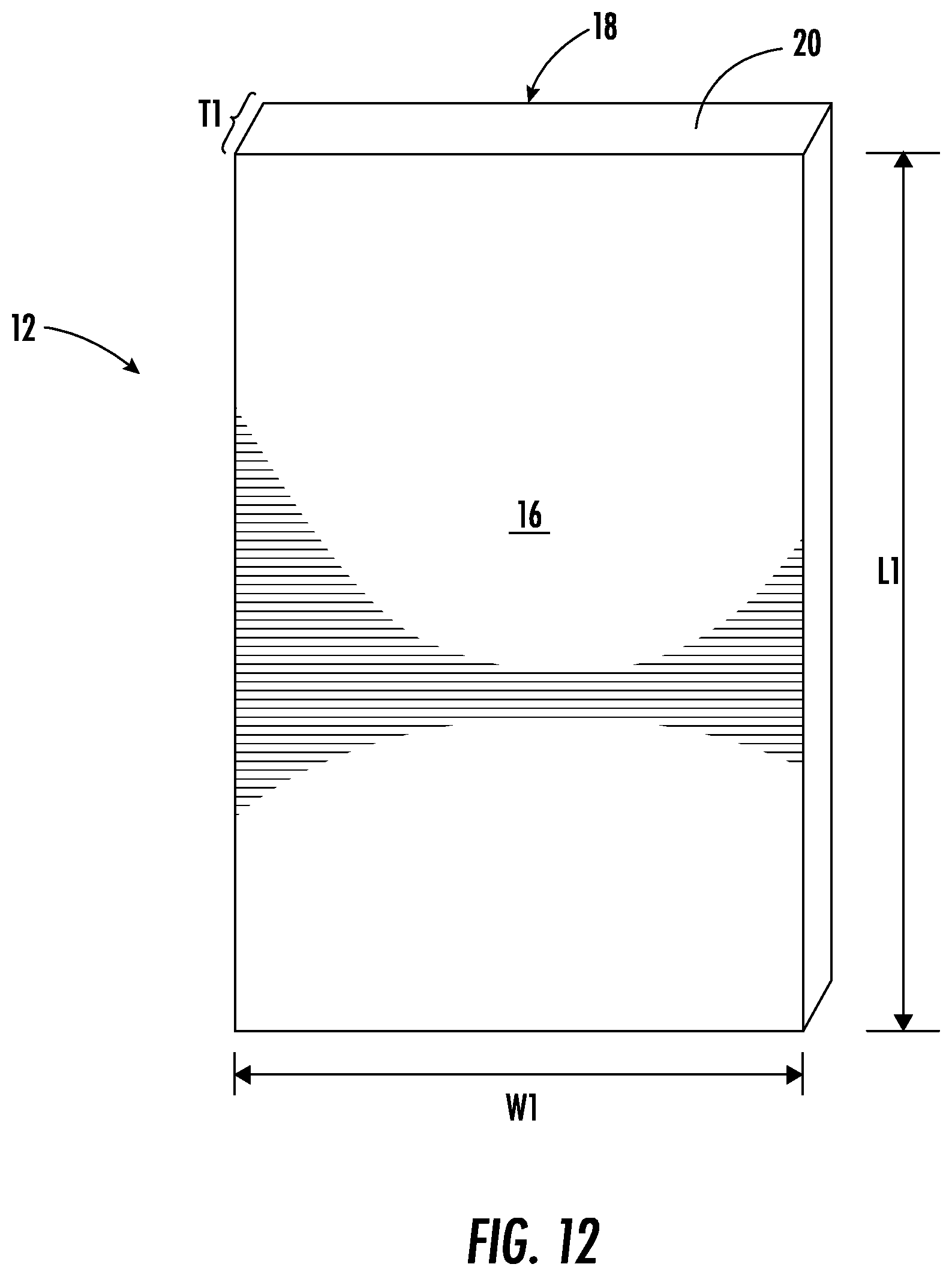
[0043] Referring to FIG. 12, additional structural details of glass sheet 12 are shown and described. As noted above, glass sheet 12 has a thickness T1 that is substantially constant and is defined as a distance between the first major surface 16 and the second major surface 18. In various embodiments, T1 may refer to an average thickness or a maximum thickness of the glass sheet. In addition, glass sheet 12 includes a width W1 defined as a first maximum dimension of one of the first or second major surfaces 16, 18 orthogonal to the thickness T1, and a length L1 defined as a second maximum dimension of one of the first or second major surfaces 16, 18 orthogonal to both the thickness and the width. In other embodiments, W1 and L1 may be the average width and the average length of glass sheet 12, respectively.
[0044] In various embodiments, thickness T1 is 2 mm or less and specifically is 0.3 mm to 1.1 mm. For example, thickness T1 may be in a range from about 0.1 mm to about 1.5 mm, from about 0.15 mm to about 1.5 mm, from about 0.2 mm to about 1.5 mm, from about 0.25 mm to about 1.5 mm, from about 0.3 mm to about 1.5 mm, from about 0.35 mm to about 1.5 mm, from about 0.4 mm to about 1.5 mm, from about 0.45 mm to about 1.5 mm, from about 0.5 mm to about 1.5 mm, from about 0.55 mm to about 1.5 mm, from about 0.6 mm to about 1.5 mm, from about 0.65 mm to about 1.5 mm, from about 0.7 mm to about 1.5 mm, from about 0.1 mm to about 1.4 mm, from about 0.1 mm to about 1.3 mm, from about 0.1 mm to about 1.2 mm, from about 0.1 mm to about 1.1 mm, from about 0.1 mm to about 1.05 mm, from about 0.1 mm to about 1 mm, from about 0.1 mm to about 0.95 mm, from about 0.1 mm to about 0.9 mm, from about 0.1 mm to about 0.85 mm, from about 0.1 mm to about 0.8 mm, from about 0.1 mm to about 0.75 mm, from about 0.1 mm to about 0.7 mm, from about 0.1 mm to about 0.65 mm, from about 0.1 mm to about 0.6 mm, from about 0.1 mm to about 0.55 mm, from about 0.1 mm to about 0.5 mm, from about 0.1 mm to about 0.4 mm, or from about 0.3 mm to about 0.7 mm. In other embodiments, the T1 falls within any one of the exact numerical ranges set forth in this paragraph.
[0045] In various embodiments, width W1 is in a range from 5 cm to 250 cm, from about 10 cm to about 250 cm, from about 15 cm to about 250 cm, from about 20 cm to about 250 cm, from about 25 cm to about 250 cm, from about 30 cm to about 250 cm, from about 35 cm to about 250 cm, from about 40 cm to about 250 cm, from about 45 cm to about 250 cm, from about 50 cm to about 250 cm, from about 55 cm to about 250 cm, from about 60 cm to about 250 cm, from about 65 cm to about 250 cm, from about 70 cm to about 250 cm, from about 75 cm to about 250 cm, from about 80 cm to about 250 cm, from about 85 cm to about 250 cm, from about 90 cm to about 250 cm, from about 95 cm to about 250 cm, from about 100 cm to about 250 cm, from about 110 cm to about 250 cm, from about 120 cm to about 250 cm, from about 130 cm to about 250 cm, from about 140 cm to about 250 cm, from about 150 cm to about 250 cm, from about 5 cm to about 240 cm, from about 5 cm to about 230 cm, from about 5 cm to about 220 cm, from about 5 cm to about 210 cm, from about 5 cm to about 200 cm, from about 5 cm to about 190 cm, from about 5 cm to about 180 cm, from about 5 cm to about 170 cm, from about 5 cm to about 160 cm, from about 5 cm to about 150 cm, from about 5 cm to about 140 cm, from about 5 cm to about 130 cm, from about 5 cm to about 120 cm, from about 5 cm to about 110 cm, from about 5 cm to about 110 cm, from about 5 cm to about 100 cm, from about 5 cm to about 90 cm, from about 5 cm to about 80 cm, or from about 5 cm to about 75 cm. In other embodiments, W1 falls within any one of the exact numerical ranges set forth in this paragraph.
[0046] In various embodiments, length L1 is in a range from about 5 cm to about 1500 cm, from about 50 cm to about 1500 cm, from about 100 cm to about 1500 cm, from about 150 cm to about 1500 cm, from about 200 cm to about 1500 cm, from about 250 cm to about 1500 cm, from about 300 cm to about 1500 cm, from about 350 cm to about 1500 cm, from about 400 cm to about 1500 cm, from about 450 cm to about 1500 cm, from about 500 cm to about 1500 cm, from about 550 cm to about 1500 cm, from about 600 cm to about 1500 cm, from about 650 cm to about 1500 cm, from about 650 cm to about 1500 cm, from about 700 cm to about 1500 cm, from about 750 cm to about 1500 cm, from about 800 cm to about 1500 cm, from about 850 cm to about 1500 cm, from about 900 cm to about 1500 cm, from about 950 cm to about 1500 cm, from about 1000 cm to about 1500 cm, from about 1050 cm to about 1500 cm, from about 1100 cm to about 1500 cm, from about 1150 cm to about 1500 cm, from about 1200 cm to about 1500 cm, from about 1250 cm to about 1500 cm, from about 1300 cm to about 1500 cm, from about 1350 cm to about 1500 cm, from about 1400 cm to about 1500 cm, or from about 1450 cm to about 1500 cm. In other embodiments, L1 falls within any one of the exact numerical ranges set forth in this paragraph.
[0047] In various embodiments, one or more radius of curvature (e.g., R1 shown in FIG. 2B) of glass sheet 12 is about 30 mm or greater. For example, R1 may be in a range from about 30 mm to about 5000 mm, from about 50 mm to about 5000 mm, from about 70 mm to about 5000 mm, from about 90 mm to about 5000 mm, from about 110 mm to about 5000 mm, from about 150 mm to about 5000 mm, from about 200 mm to about 5000 mm, from about 250 mm to about 5000 mm, from about 300 mm to about 5000 mm, from about 350 mm to about 5000 mm, from about 400 mm to about 5000 mm, from about 450 mm to about 5000 mm, from about 500 mm to about 5000 mm, from about 550 mm to about 5000 mm, from about 600 mm to about 5000 mm, from about 650 mm to about 5000 mm, from about 700 mm to about 5000 mm, from about 750 mm to about 5000 mm, from about 800 mm to about 5000 mm, from about 850 mm to about 5000 mm, from about 900 mm to about 5000 mm, from about 950 mm to about 5000 mm, from about 1000 mm to about 5000 mm, from about 1500 mm to about 5000 mm, from about 2000 mm to about 5000 mm, from about 2500 mm to about 5000 mm, from about 3000 mm to about 5000 mm, from about 3500 mm to about 5000 mm, from about 4000 mm to about 5000 mm, from about 4500 mm to about 5000 mm, from about 30 mm to about 4500 mm, from about 30 mm to about 4000 mm, from about 30 mm to about 3500 mm, from about 30 mm to about 3000 mm, from about 30 mm to about 2500 mm, from about 30 mm to about 2000 mm, from about 30 mm to about 1500 mm, from about 30 mm to about 1000 mm, from about 30 mm to about 950 mm, from about 30 mm to about 900 mm, from about 30 mm to about 850 mm, from about 30 mm to about 800 mm, from about 30 mm to about 750 mm, from about 30 mm to about 700 mm, from about 30 mm to about 650 mm, from about 30 mm to about 600 mm, from about 30 mm to about 550 mm, from about 30 mm to about 500 mm, from about 30 mm to about 450 mm, or from about 30 mm to about 400 mm. In other embodiments, R1 falls within any one of the exact numerical ranges set forth in this paragraph.
[0048] The various embodiments of the vehicle interior system may be incorporated into vehicles such as trains, automobiles (e.g., cars, trucks, buses and the like), sea craft (boats, ships, submarines, and the like), and aircraft (e.g., drones, airplanes, jets, helicopters and the like).
Strengthened Glass Properties
[0049] As noted above, glass sheet 12 may be strengthened. In one or more embodiments, glass sheet 12 may be strengthened to include compressive stress that extends from a surface to a depth of compression (DOC). The compressive stress regions are balanced by a central portion exhibiting a tensile stress. At the DOC, the stress crosses from a positive (compressive) stress to a negative (tensile) stress.
[0050] In various embodiments, glass sheet 12 may be strengthened mechanically by utilizing a mismatch of the coefficient of thermal expansion between portions of the article to create a compressive stress region and a central region exhibiting a tensile stress. In some embodiments, the glass sheet may be strengthened thermally by heating the glass to a temperature above the glass transition point and then rapidly quenching.
[0051] In various embodiments, glass sheet 12 may be chemically strengthened by ion exchange. In the ion exchange process, ions at or near the surface of the glass sheet are replaced by--or exchanged with--larger ions having the same valence or oxidation state. In those embodiments in which the glass sheet comprises an alkali aluminosilicate glass, ions in the surface layer of the article and the larger ions are monovalent alkali metal cations, such as Li.sup.+, Na.sup.+, K.sup.+, Rb.sup.+, and Cs.sup.+. Alternatively, monovalent cations in the surface layer may be replaced with monovalent cations other than alkali metal cations, such as Ag.sup.+ or the like. In such embodiments, the monovalent ions (or cations) exchanged into the glass sheet generate a stress.
[0052] Ion exchange processes are typically carried out by immersing a glass sheet in a molten salt bath (or two or more molten salt baths) containing the larger ions to be exchanged with the smaller ions in the glass sheet. It should be noted that aqueous salt baths may also be utilized. In addition, the composition of the bath(s) may include more than one type of larger ions (e.g., Na.sup.+ and K.sup.+) or a single larger ion. It will be appreciated by those skilled in the art that parameters for the ion exchange process, including, but not limited to, bath composition and temperature, immersion time, the number of immersions of the glass sheet in a salt bath (or baths), use of multiple salt baths, additional steps such as annealing, washing, and the like, are generally determined by the composition of the glass sheet (including the structure of the article and any crystalline phases present) and the desired DOC and CS of the glass sheet that results from strengthening. Exemplary molten bath compositions may include nitrates, sulfates, and chlorides of the larger alkali metal ion. Typical nitrates include KNO.sub.3, NaNO.sub.3, LiNO.sub.3, NaSO.sub.4 and combinations thereof. The temperature of the molten salt bath typically is in a range from about 380.degree. C. up to about 450.degree. C., while immersion times range from about 15 minutes up to about 100 hours depending on glass sheet thickness, bath temperature and glass (or monovalent ion) diffusivity. However, temperatures and immersion times different from those described above may also be used.
[0053] In one or more embodiments, the glass sheets may be immersed in a molten salt bath of 100% NaNO.sub.3, 100% KNO.sub.3, or a combination of NaNO.sub.3 and KNO.sub.3 having a temperature from about 370.degree. C. to about 480.degree. C. In some embodiments, the glass sheet may be immersed in a molten mixed salt bath including from about 5% to about 90% KNO.sub.3 and from about 10% to about 95% NaNO.sub.3. In one or more embodiments, the glass sheet may be immersed in a second bath, after immersion in a first bath. The first and second baths may have different compositions and/or temperatures from one another. The immersion times in the first and second baths may vary. For example, immersion in the first bath may be longer than the immersion in the second bath.
[0054] In one or more embodiments, the glass sheet may be immersed in a molten, mixed salt bath including NaNO.sub.3 and KNO.sub.3 (e.g., 49%/51%, 50%/50%, 51%/49%) having a temperature less than about 420.degree. C. (e.g., about 400.degree. C. or about 380.degree. C.). for less than about 5 hours, or even about 4 hours or less.
[0055] Ion exchange conditions can be tailored to provide a "spike" or to increase the slope of the stress profile at or near the surface of the resulting glass sheet. The spike may result in a greater surface CS value. This spike can be achieved by a single bath or multiple baths, with the bath(s) having a single composition or mixed composition, due to the unique properties of the glass compositions used in the glass sheets described herein.
[0056] In one or more embodiments, where more than one monovalent ion is exchanged into the glass sheet, the different monovalent ions may exchange to different depths within the glass sheet (and generate different magnitudes stresses within the glass sheet at different depths). The resulting relative depths of the stress-generating ions can be determined and cause different characteristics of the stress profile.
[0057] CS is measured using those means known in the art, such as by surface stress meter (FSM) using commercially available instruments such as the FSM-6000, manufactured by Orihara Industrial Co., Ltd. (Japan). Surface stress measurements rely upon the accurate measurement of the stress optical coefficient (SOC), which is related to the birefringence of the glass. SOC in turn is measured by those methods that are known in the art, such as fiber and four point bend methods, both of which are described in ASTM standard C770-98 (2013), entitled "Standard Test Method for Measurement of Glass Stress-Optical Coefficient," the contents of which are incorporated herein by reference in their entirety, and a bulk cylinder method. As used herein CS may be the "maximum compressive stress" which is the highest compressive stress value measured within the compressive stress layer. In some embodiments, the maximum compressive stress is located at the surface of the glass sheet. In other embodiments, the maximum compressive stress may occur at a depth below the surface, giving the compressive profile the appearance of a "buried peak."
[0058] DOC may be measured by FSM or by a scattered light polariscope (SCALP) (such as the SCALP-04 scattered light polariscope available from Glasstress Ltd., located in Tallinn Estonia), depending on the strengthening method and conditions. When the glass sheet is chemically strengthened by an ion exchange treatment, FSM or SCALP may be used depending on which ion is exchanged into the glass sheet. Where the stress in the glass sheet is generated by exchanging potassium ions into the glass sheet, FSM is used to measure DOC. Where the stress is generated by exchanging sodium ions into the glass sheet, SCALP is used to measure DOC. Where the stress in the glass sheet is generated by exchanging both potassium and sodium ions into the glass, the DOC is measured by SCALP, since it is believed the exchange depth of sodium indicates the DOC and the exchange depth of potassium ions indicates a change in the magnitude of the compressive stress (but not the change in stress from compressive to tensile); the exchange depth of potassium ions in such glass sheets is measured by FSM. Central tension or CT is the maximum tensile stress and is measured by SCALP.
[0059] In one or more embodiments, the glass sheet may be strengthened to exhibit a DOC that is described as a fraction of the thickness T1 of the glass sheet (as described herein). For example, in one or more embodiments, the DOC may be equal to or greater than about 0.05T1, equal to or greater than about 0.1T1, equal to or greater than about 0.11T1, equal to or greater than about 0.12T1, equal to or greater than about 0.13T1, equal to or greater than about 0.14T1, equal to or greater than about 0.15T1, equal to or greater than about 0.16T1, equal to or greater than about 0.17T1, equal to or greater than about 0.18T1, equal to or greater than about 0.19T1, equal to or greater than about 0.2T1, equal to or greater than about 0.21T1. In some embodiments, the DOC may be in a range from about 0.08T1 to about 0.25T1, from about 0.09T1 to about 0.25T1, from about 0.18T1 to about 0.25T1, from about 0.11T1 to about 0.25T1, from about 0.12T1 to about 0.25T1, from about 0.13T1 to about 0.25T1, from about 0.14T1 to about 0.25T1, from about 0.15T1 to about 0.25T1, from about 0.08T1 to about 0.24T1, from about 0.08T1 to about 0.23T1, from about 0.08T1 to about 0.22T1, from about 0.08T1 to about 0.21T1, from about 0.08T1 to about 0.2T1, from about 0.08T1 to about 0.19T1, from about 0.08T1 to about 0.18T1, from about 0.08T1 to about 0.17T1, from about 0.08T1 to about 0.16T1, or from about 0.08T1 to about 0.15T1. In some instances, the DOC may be about 20 .mu.m or less. In one or more embodiments, the DOC may be about 40 .mu.m or greater (e.g., from about 40 .mu.m to about 300 .mu.m, from about 50 .mu.m to about 300 .mu.m, from about 60 .mu.m to about 300 .mu.m, from about 70 .mu.m to about 300 .mu.m, from about 80 .mu.m to about 300 .mu.m, from about 90 .mu.m to about 300 .mu.m, from about 100 .mu.m to about 300 .mu.m, from about 110 .mu.m to about 300 .mu.m, from about 120 .mu.m to about 300 .mu.m, from about 140 .mu.m to about 300 .mu.m, from about 150 .mu.m to about 300 .mu.m, from about 40 .mu.m to about 290 .mu.m, from about 40 .mu.m to about 280 .mu.m, from about 40 .mu.m to about 260 .mu.m, from about 40 .mu.m to about 250 .mu.m, from about 40 .mu.m to about 240 .mu.m, from about 40 .mu.m to about 230 .mu.m, from about 40 .mu.m to about 220 .mu.m, from about 40 .mu.m to about 210 .mu.m, from about 40 .mu.m to about 200 .mu.m, from about 40 .mu.m to about 180 .mu.m, from about 40 .mu.m to about 160 .mu.m, from about 40 .mu.m to about 150 .mu.m, from about 40 .mu.m to about 140 .mu.m, from about 40 .mu.m to about 130 .mu.m, from about 40 .mu.m to about 120 .mu.m, from about 40 .mu.m to about 110 .mu.m, or from about 40 .mu.m to about 100 .mu.m. In other embodiments, DOC falls within any one of the exact numerical ranges set forth in this paragraph.
[0060] In one or more embodiments, the strengthened glass sheet may have a CS (which may be found at the surface or a depth within the glass sheet) of about 200 MPa or greater, 300 MPa or greater, 400 MPa or greater, about 500 MPa or greater, about 600 MPa or greater, about 700 MPa or greater, about 800 MPa or greater, about 900 MPa or greater, about 930 MPa or greater, about 1000 MPa or greater, or about 1050 MPa or greater.
[0061] In one or more embodiments, the strengthened glass sheet may have a maximum tensile stress or central tension (CT) of about 20 MPa or greater, about 30 MPa or greater, about 40 MPa or greater, about 45 MPa or greater, about 50 MPa or greater, about 60 MPa or greater, about 70 MPa or greater, about 75 MPa or greater, about 80 MPa or greater, or about 85 MPa or greater. In some embodiments, the maximum tensile stress or central tension (CT) may be in a range from about 40 MPa to about 100 MPa. In other embodiments, CS falls within the exact numerical ranges set forth in this paragraph.
Glass Compositions
[0062] Suitable glass compositions for use in glass sheet 12 include soda lime glass, aluminosilicate glass, borosilicate glass, boroaluminosilicate glass, alkali-containing aluminosilicate glass, alkali-containing borosilicate glass, and alkali-containing boroaluminosilicate glass.
[0063] Unless otherwise specified, the glass compositions disclosed herein are described in mole percent (mol %) as analyzed on an oxide basis.
[0064] In one or more embodiments, the glass composition may include SiO.sub.2 in an amount in a range from about 66 mol % to about 80 mol %, from about 67 mol % to about 80 mol %, from about 68 mol % to about 80 mol %, from about 69 mol % to about 80 mol %, from about 70 mol % to about 80 mol %, from about 72 mol % to about 80 mol %, from about 65 mol % to about 78 mol %, from about 65 mol % to about 76 mol %, from about 65 mol % to about 75 mol %, from about 65 mol % to about 74 mol %, from about 65 mol % to about 72 mol %, or from about 65 mol % to about 70 mol %, and all ranges and sub-ranges therebetween.
[0065] In one or more embodiments, the glass composition includes Al.sub.2O.sub.3 in an amount greater than about 4 mol %, or greater than about 5 mol %. In one or more embodiments, the glass composition includes Al.sub.2O.sub.3 in a range from greater than about 7 mol % to about 15 mol %, from greater than about 7 mol % to about 14 mol %, from about 7 mol % to about 13 mol %, from about 4 mol % to about 12 mol %, from about 7 mol % to about 11 mol %, from about 8 mol % to about 15 mol %, from about 9 mol % to about 15 mol %, from about 10 mol % to about 15 mol %, from about 11 mol % to about 15 mol %, or from about 12 mol % to about 15 mol %, and all ranges and sub-ranges therebetween. In one or more embodiments, the upper limit of Al.sub.2O.sub.3 may be about 14 mol %, 14.2 mol %, 14.4 mol %, 14.6 mol %, or 14.8 mol %.
[0066] In one or more embodiments, the glass article is described as an aluminosilicate glass article or including an aluminosilicate glass composition. In such embodiments, the glass composition or article formed therefrom includes SiO.sub.2 and Al.sub.2O.sub.3 and is not a soda lime silicate glass. In this regard, the glass composition or article formed therefrom includes Al.sub.2O.sub.3 in an amount of about 2 mol % or greater, 2.25 mol % or greater, 2.5 mol % or greater, about 2.75 mol % or greater, about 3 mol % or greater.
[0067] In one or more embodiments, the glass composition comprises B.sub.2O.sub.3 (e.g., about 0.01 mol % or greater). In one or more embodiments, the glass composition comprises B.sub.2O.sub.3 in an amount in a range from about 0 mol % to about 5 mol %, from about 0 mol % to about 4 mol %, from about 0 mol % to about 3 mol %, from about 0 mol % to about 2 mol %, from about 0 mol % to about 1 mol %, from about 0 mol % to about 0.5 mol %, from about 0.1 mol % to about 5 mol %, from about 0.1 mol % to about 4 mol %, from about 0.1 mol % to about 3 mol %, from about 0.1 mol % to about 2 mol %, from about 0.1 mol % to about 1 mol %, from about 0.1 mol % to about 0.5 mol %, and all ranges and sub-ranges therebetween. In one or more embodiments, the glass composition is substantially free of B.sub.2O.sub.3.
[0068] As used herein, the phrase "substantially free" with respect to the components of the composition means that the component is not actively or intentionally added to the composition during initial batching, but may be present as an impurity in an amount less than about 0.001 mol %.
[0069] In one or more embodiments, the glass composition optionally comprises P.sub.2O.sub.5 (e.g., about 0.01 mol % or greater). In one or more embodiments, the glass composition comprises a non-zero amount of P.sub.2O.sub.5 up to and including 2 mol %, 1.5 mol %, 1 mol %, or 0.5 mol %. In one or more embodiments, the glass composition is substantially free of P.sub.2O.sub.5.
[0070] In one or more embodiments, the glass composition may include a total amount of R.sub.2O (which is the total amount of alkali metal oxide such as Li.sub.2O, Na.sub.2O, K.sub.2O, Rb.sub.2O, and Cs.sub.2O) that is greater than or equal to about 8 mol %, greater than or equal to about 10 mol %, or greater than or equal to about 12 mol %. In some embodiments, the glass composition includes a total amount of R.sub.2O in a range from about 8 mol % to about 20 mol %, from about 8 mol % to about 18 mol %, from about 8 mol % to about 16 mol %, from about 8 mol % to about 14 mol %, from about 8 mol % to about 12 mol %, from about 9 mol % to about 20 mol %, from about 10 mol % to about 20 mol %, from about 11 mol % to about 20 mol %, from about 12 mol % to about 20 mol %, from about 13 mol % to about 20 mol %, from about 10 mol % to about 14 mol %, or from 11 mol % to about 13 mol %, and all ranges and sub-ranges therebetween. In one or more embodiments, the glass composition may be substantially free of Rb.sub.2O, Cs.sub.2O or both Rb.sub.2O and Cs.sub.2O. In one or more embodiments, the R.sub.2O may include the total amount of Li.sub.2O, Na.sub.2O and K.sub.2O only. In one or more embodiments, the glass composition may comprise at least one alkali metal oxide selected from Li.sub.2O, Na.sub.2O and K.sub.2O, wherein the alkali metal oxide is present in an amount greater than about 8 mol % or greater.
[0071] In one or more embodiments, the glass composition comprises Na.sub.2O in an amount greater than or equal to about 8 mol %, greater than or equal to about 10 mol %, or greater than or equal to about 12 mol %. In one or more embodiments, the composition includes Na.sub.2O in a range from about from about 8 mol % to about 20 mol %, from about 8 mol % to about 18 mol %, from about 8 mol % to about 16 mol %, from about 8 mol % to about 14 mol %, from about 8 mol % to about 12 mol %, from about 9 mol % to about 20 mol %, from about 10 mol % to about 20 mol %, from about 11 mol % to about 20 mol %, from about 12 mol % to about 20 mol %, from about 13 mol % to about 20 mol %, from about 10 mol % to about 14 mol %, or from 11 mol % to about 16 mol %, and all ranges and sub-ranges therebetween.
[0072] In one or more embodiments, the glass composition includes less than about 4 mol % K.sub.2O, less than about 3 mol % K.sub.2O, or less than about 1 mol % K.sub.2O. In some instances, the glass composition may include K.sub.2O in an amount in a range from about 0 mol % to about 4 mol %, from about 0 mol % to about 3.5 mol %, from about 0 mol % to about 3 mol %, from about 0 mol % to about 2.5 mol %, from about 0 mol % to about 2 mol %, from about 0 mol % to about 1.5 mol %, from about 0 mol % to about 1 mol %, from about 0 mol % to about 0.5 mol %, from about 0 mol % to about 0.2 mol %, from about 0 mol % to about 0.1 mol %, from about 0.5 mol % to about 4 mol %, from about 0.5 mol % to about 3.5 mol %, from about 0.5 mol % to about 3 mol %, from about 0.5 mol % to about 2.5 mol %, from about 0.5 mol % to about 2 mol %, from about 0.5 mol % to about 1.5 mol %, or from about 0.5 mol % to about 1 mol %, and all ranges and sub-ranges therebetween. In one or more embodiments, the glass composition may be substantially free of K.sub.2O.
[0073] In one or more embodiments, the glass composition is substantially free of Li.sub.2O.
[0074] In one or more embodiments, the amount of Na.sub.2O in the composition may be greater than the amount of Li.sub.2O. In some instances, the amount of Na.sub.2O may be greater than the combined amount of Li.sub.2O and K.sub.2O. In one or more alternative embodiments, the amount of Li.sub.2O in the composition may be greater than the amount of Na.sub.2O or the combined amount of Na.sub.2O and K.sub.2O.
[0075] In one or more embodiments, the glass composition may include a total amount of RO (which is the total amount of alkaline earth metal oxide such as CaO, MgO, BaO, ZnO and SrO) in a range from about 0 mol % to about 2 mol %. In some embodiments, the glass composition includes a non-zero amount of RO up to about 2 mol %. In one or more embodiments, the glass composition comprises RO in an amount from about 0 mol % to about 1.8 mol %, from about 0 mol % to about 1.6 mol %, from about 0 mol % to about 1.5 mol %, from about 0 mol % to about 1.4 mol %, from about 0 mol % to about 1.2 mol %, from about 0 mol % to about 1 mol %, from about 0 mol % to about 0.8 mol %, from about 0 mol % to about 0.5 mol %, and all ranges and sub-ranges therebetween.
[0076] In one or more embodiments, the glass composition includes CaO in an amount less than about 1 mol %, less than about 0.8 mol %, or less than about 0.5 mol %. In one or more embodiments, the glass composition is substantially free of CaO.
[0077] In some embodiments, the glass composition comprises MgO in an amount from about 0 mol % to about 7 mol %, from about 0 mol % to about 6 mol %, from about 0 mol % to about 5 mol %, from about 0 mol % to about 4 mol %, from about 0.1 mol % to about 7 mol %, from about 0.1 mol % to about 6 mol %, from about 0.1 mol % to about 5 mol %, from about 0.1 mol % to about 4 mol %, from about 1 mol % to about 7 mol %, from about 2 mol % to about 6 mol %, or from about 3 mol % to about 6 mol %, and all ranges and sub-ranges therebetween.
[0078] In one or more embodiments, the glass composition comprises ZrO.sub.2 in an amount equal to or less than about 0.2 mol %, less than about 0.18 mol %, less than about 0.16 mol %, less than about 0.15 mol %, less than about 0.14 mol %, less than about 0.12 mol %. In one or more embodiments, the glass composition comprises ZrO.sub.2 in a range from about 0.01 mol % to about 0.2 mol %, from about 0.01 mol % to about 0.18 mol %, from about 0.01 mol % to about 0.16 mol %, from about 0.01 mol % to about 0.15 mol %, from about 0.01 mol % to about 0.14 mol %, from about 0.01 mol % to about 0.12 mol %, or from about 0.01 mol % to about 0.10 mol %, and all ranges and sub-ranges therebetween.
[0079] In one or more embodiments, the glass composition comprises SnO.sub.2 in an amount equal to or less than about 0.2 mol %, less than about 0.18 mol %, less than about 0.16 mol %, less than about 0.15 mol %, less than about 0.14 mol %, less than about 0.12 mol %. In one or more embodiments, the glass composition comprises SnO.sub.2 in a range from about 0.01 mol % to about 0.2 mol %, from about 0.01 mol % to about 0.18 mol %, from about 0.01 mol % to about 0.16 mol %, from about 0.01 mol % to about 0.15 mol %, from about 0.01 mol % to about 0.14 mol %, from about 0.01 mol % to about 0.12 mol %, or from about 0.01 mol % to about 0.10 mol %, and all ranges and sub-ranges therebetween.
[0080] In one or more embodiments, the glass composition may include an oxide that imparts a color or tint to the glass articles. In some embodiments, the glass composition includes an oxide that prevents discoloration of the glass article when the glass article is exposed to ultraviolet radiation. Examples of such oxides include, without limitation oxides of: Ti, V, Cr, Mn, Fe, Co, Ni, Cu, Ce, W, and Mo.
[0081] In one or more embodiments, the glass composition includes Fe expressed as Fe.sub.2O.sub.3, wherein Fe is present in an amount up to (and including) about 1 mol %. In some embodiments, the glass composition is substantially free of Fe. In one or more embodiments, the glass composition comprises Fe.sub.2O.sub.3 in an amount equal to or less than about 0.2 mol %, less than about 0.18 mol %, less than about 0.16 mol %, less than about 0.15 mol %, less than about 0.14 mol %, less than about 0.12 mol %. In one or more embodiments, the glass composition comprises Fe.sub.2O.sub.3 in a range from about 0.01 mol % to about 0.2 mol %, from about 0.01 mol % to about 0.18 mol %, from about 0.01 mol % to about 0.16 mol %, from about 0.01 mol % to about 0.15 mol %, from about 0.01 mol % to about 0.14 mol %, from about 0.01 mol % to about 0.12 mol %, or from about 0.01 mol % to about 0.10 mol %, and all ranges and sub-ranges therebetween.
[0082] Where the glass composition includes TiO.sub.2, TiO.sub.2 may be present in an amount of about 5 mol % or less, about 2.5 mol % or less, about 2 mol % or less or about 1 mol % or less. In one or more embodiments, the glass composition may be substantially free of TiO.sub.2.
[0083] An exemplary glass composition includes SiO.sub.2 in an amount in a range from about 65 mol % to about 75 mol %, Al.sub.2O.sub.3 in an amount in a range from about 8 mol % to about 14 mol %, Na.sub.2O in an amount in a range from about 12 mol % to about 17 mol %, K.sub.2O in an amount in a range of about 0 mol % to about 0.2 mol %, and MgO in an amount in a range from about 1.5 mol % to about 6 mol %. Optionally, SnO.sub.2 may be included in the amounts otherwise disclosed herein. It should be understood, that while the preceding glass composition paragraphs express approximate ranges, in other embodiments, glass sheet 134 may be made from any glass composition falling with any one of the exact numerical ranges discussed above.
[0084] Aspect (1) of this disclosure pertains to a method of forming a curved glass article, comprising the steps of: providing a mold comprising a curved surface, wherein a self-adhesive layer is disposed on the curved surface; bending a glass sheet into conformity with the curved surface at a temperature less than the glass transition temperature of the glass sheet, wherein the glass sheet comprises a first major surface and a second major surface, wherein the second major surface is opposite to the first major surface, and wherein the first major surface is adhered to the self-adhesive layer; bonding a frame to the second major surface of the glass sheet; and removing the glass sheet from the self-adhesive layer. In one or more embodiments, Aspect (1) pertains to a method of forming a curved glass article, comprising the steps of: bending a glass sheet at a temperature less than the glass transition temperature of the glass sheet to confirm with a curved surface of a mold comprising a self-adhesive layer disposed on the curved surface, wherein the glass sheet comprises a first major surface and a second major surface, wherein the second major surface is opposite to the first major surface, and wherein the first major surface is adhered to the self-adhesive layer; bonding a frame to the second major surface of the glass sheet; and removing the glass sheet from the self-adhesive layer.
[0085] Aspect (2) pertains to the method of Aspect (1), wherein bonding further comprising applying an adhesive to the frame or to the second major surface of the glass sheet, positioning the frame on the second major surface, and curing the adhesive.
[0086] Aspect (3) pertains to the method of Aspect (2), wherein the adhesive comprises at least one of a toughened adhesive, a flexible epoxy, an acrylic, a urethane, or a silicone.
[0087] Aspect (4) pertains to the method of any one of Aspects (1) through (3), wherein the self-adhesive layer comprises at least one of a polyurethane, a silicone, an acrylic, a polyester, a polyolefin, a polyacrylamide, or a polyether-urethane copolymer.
[0088] Aspect (5) pertains to the method of any one of Aspects (1) through (4), wherein the curved surface comprises at least one of a convex curvature or a concave curvature
[0089] Aspect (6) pertains to the method of any one of Aspects (1) through (5), wherein the curved surface comprises both a convex curvature and a concave curvature.
[0090] Aspect (7) pertains to the method of any one of Aspects (1) through (6), wherein the curved surface has a radius of curvature of from 30 mm to 5 m.
[0091] Aspect (8) pertains to the method of any one of Aspects (1) through (7), wherein bending takes place at a temperature of less than 200.degree. C.
[0092] Aspect (9) pertains to the method of any one of Aspects (1) through (8), wherein the mold further comprises a plurality of vacuum channels and wherein the method further comprises applying a negative pressure to the first major surface of the glass sheet to keep the glass sheet in conformity with the curved surface.
[0093] Aspect (10) pertains to the method of Aspect (9), wherein releasing the glass sheet from the self-adhesive layer further comprising applying a positive pressure to the first major surface to push the glass sheet away from the self-adhesive layer.
[0094] Aspect (11) pertains to the method of any one of Aspects (1) through (10), wherein the glass sheet has a thickness between the first major surface and the second major surface of from 0.4 mm to 2.0 mm.
[0095] Aspect (12) pertains to the method of any one of Aspects (1) through (11), further comprising bonding a display to the second major surface using optically clear adhesive.
[0096] Aspect (13) pertains to the method of Aspect (12), wherein the display comprises at least one of a light-emitting diode display, an organic light-emitting diode display, a plasma display, or a liquid crystal display.
[0097] Aspect (14) pertains to the method of any one of Aspects (1) through (13), wherein the glass sheet comprises at least one of soda lime glass, aluminosilicate glass, borosilicate glass, boroaluminosilicate glass, alkali-containing aluminosilicate glass, alkali-containing borosilicate glass, and alkali-containing boroaluminosilicate glass.
[0098] Aspect (15) pertains to the method of any one of Aspects (1) through (14), wherein the first major surface and the second major surface are chemically strengthened.
[0099] Aspect (16) pertains to the method of any one of Aspects (1) through (15), further comprising applying a surface treatment to at least one of the first major surface or the second major surface prior to bending.
[0100] Aspect (17) pertains to the method of Aspect (16), wherein the surface treatment is at least one of an anti-glare treatment, an anti-reflective coating, and easy-to-clean coating.
[0101] Aspect (18) pertains to a system for cold-forming curved glass articles, comprising: a conveyor system; a plurality of molds arranged on the conveyor system, each of the plurality of molds comprising a curved surface and a self-adhesive layer; wherein at a first position on the conveyor system, a first major surface of a glass sheet is adhered to the self-adhesive layer of one mold of the first plurality of molds; wherein at a second position on the conveyor system, a frame is positioned on and adhered to a second major surface of the glass sheet, wherein the second major surface is opposite to the first major surface; wherein at a final position on the conveyor system, the glass sheet with bonded frame is removed from the mold; and wherein between the second position and the final position, the conveyor system has a length and speed configured to allow curing of the frame adhered to the glass sheet.
[0102] Aspect (19) pertains to the system of Aspect (18), wherein the self-adhesive layer comprises at least one of polyurethane, a silicone, an acrylic, a polyester, a polyolefin, a polyacrylamide, or a polyether-urethane copolymer.
[0103] Aspect (20) pertains to the system of Aspect (18) or Aspect (19), wherein the curved surface comprises at least one of a convex curvature or a concave curvature
[0104] Aspect (21) pertains to the system of anyone of Aspects (18) through (20), wherein the curved surface comprises both a convex curvature and a concave curvature.
[0105] Aspect (22) pertains to the system of anyone of Aspects (18) through (21), wherein the curved surface has a radius of curvature of from 30 mm to 5 m.
[0106] Aspect (23) pertains to the system of anyone of Aspects (18) through (22), wherein the system is operated at a temperature of less than 200.degree. C.
[0107] Aspect (24) pertains to the system of anyone of Aspects (18) through (23), wherein the second position comprises a first robotic arm configured to position the frame on the second surface of the glass sheet.
[0108] Aspect (25) pertains to the system of anyone of Aspects (18) through (24), wherein the final position comprises a second robotic arm configured to remove the glass sheet with bonded frame from the self-releasing adhesive layer of the mold.
[0109] Aspect (26) pertains to the system of anyone of Aspects (18) through (24), further comprising a vacuum system configured to apply a negative pressure to a glass sheet adhered to the self-adhesive layer through a plurality of vacuum channels formed into at least one of the plurality of molds.
[0110] Aspect (27) pertains to the system of Aspect (26), wherein the vacuum system is also configured to apply a positive pressure to a glass sheet to facilitate releasing the glass sheet from the self-adhesive layer at the final position.
[0111] Aspect (28) pertains to a mold for forming a curved glass article, the mold comprising: a curved surface; and a self-adhesive layer disposed on the curved surface; wherein the self-adhesive layer comprises at least one of a polyurethane, a silicone, an acrylic, a polyester, a polyolefin, a polyacrylamide, or a polyether-urethane copolymer; and wherein the curved surface comprises at least one of a convex curvature or a concave curvature.
[0112] Aspect (29) pertains to the system of Aspect (28), wherein the curved surface comprises both a convex curvature and a concave curvature.
[0113] Aspect (30) pertains to the system of Aspect (28) or Aspect (29), wherein the curved surface has a radius of curvature of from 30 mm to 5 m.
[0114] Aspect (31) pertains to the system of anyone of Aspects (28) through (30), further comprising vacuum channels formed into the mold, wherein the vacuum channels are configured to allow a positive or negative pressure to be applied to a glass sheet.
[0115] Aspect (32) pertains to the system of anyone of Aspects (28) through (31), wherein the self-adhesive layer has an adhesion force of from 1 kgf/cm.sup.2 to 10 kgf/cm.sup.2.
[0116] Unless otherwise expressly stated, it is in no way intended that any method set forth herein be construed as requiring that its steps be performed in a specific order. Accordingly, where a method claim does not actually recite an order to be followed by its steps or it is not otherwise specifically stated in the claims or descriptions that the steps are to be limited to a specific order, it is in no way intended that any particular order be inferred. In addition, as used herein, the article "a" is intended to include one or more than one component or element, and is not intended to be construed as meaning only one.
[0117] It will be apparent to those skilled in the art that various modifications and variations can be made without departing from the spirit or scope of the disclosed embodiments. Since modifications, combinations, sub-combinations and variations of the disclosed embodiments incorporating the spirit and substance of the embodiments may occur to persons skilled in the art, the disclosed embodiments should be construed to include everything within the scope of the appended claims and their equivalents.
* * * * *
D00000
D00001
D00002
D00003
D00004
D00005
D00006
D00007
XML
uspto.report is an independent third-party trademark research tool that is not affiliated, endorsed, or sponsored by the United States Patent and Trademark Office (USPTO) or any other governmental organization. The information provided by uspto.report is based on publicly available data at the time of writing and is intended for informational purposes only.
While we strive to provide accurate and up-to-date information, we do not guarantee the accuracy, completeness, reliability, or suitability of the information displayed on this site. The use of this site is at your own risk. Any reliance you place on such information is therefore strictly at your own risk.
All official trademark data, including owner information, should be verified by visiting the official USPTO website at www.uspto.gov. This site is not intended to replace professional legal advice and should not be used as a substitute for consulting with a legal professional who is knowledgeable about trademark law.