Pneumatic Vehicle Tire For A Vehicle
Reese; Wolfgang ; et al.
U.S. patent application number 17/046153 was filed with the patent office on 2021-02-04 for pneumatic vehicle tire for a vehicle. This patent application is currently assigned to Continental Reifen Deutschland GmbH. The applicant listed for this patent is Continental Reifen Deutschland GmbH. Invention is credited to Thomas Kramer, Wolfgang Reese.
| Application Number | 20210031563 17/046153 |
| Document ID | / |
| Family ID | 1000005163217 |
| Filed Date | 2021-02-04 |

| United States Patent Application | 20210031563 |
| Kind Code | A1 |
| Reese; Wolfgang ; et al. | February 4, 2021 |
PNEUMATIC VEHICLE TIRE FOR A VEHICLE
Abstract
The invention relates to a pneumatic vehicle tire for passenger cars comprising a carcass (2), a tread (6) and a belt (7) which has belt plies (7a, 7b) and which is covered radially outwardly by a belt bandage (8) having strengthening elements oriented approximately in the circumferential direction, wherein the belt bandage (8) has at least one belt bandage ply (8a) which--as viewed in the tire cross section--consists of three sections, namely a central section (10) and two lateral sections (11, 12), wherein one lateral section (11) is arranged to the left of the central section (10) and one lateral section (12) is arranged to the right of the central section (10) and wherein the strengthening elements of the central section (10) have the construction x1 and wherein the strengthening elements of the two lateral sections (11, 12) have identical cords consisting of at least two twisted-together yarns. The invention is distinguished by the fact that the two lateral sections (11, 12) are arranged next to the central section (10), that is to say without overlapping with the central section (10), that the density of the strengthening elements in the central section (10) is less than the density of the strengthening elements in the lateral sections (11, 12), and that the end of the lateral sections (13) that points toward the central section (10) in each case has a distance (14) of 5 mm-30 mm, preferably a distance (14) of 5 mm-15 mm, from the outer end of the widest belt ply (15), where the distance (14) is measured in the axial direction (aR).
| Inventors: | Reese; Wolfgang; (Peine, DE) ; Kramer; Thomas; (Herford, DE) | ||||||||||
| Applicant: |
|
||||||||||
|---|---|---|---|---|---|---|---|---|---|---|---|
| Assignee: | Continental Reifen Deutschland
GmbH Hannover DE |
||||||||||
| Family ID: | 1000005163217 | ||||||||||
| Appl. No.: | 17/046153 | ||||||||||
| Filed: | February 4, 2019 | ||||||||||
| PCT Filed: | February 4, 2019 | ||||||||||
| PCT NO: | PCT/EP2019/052591 | ||||||||||
| 371 Date: | October 8, 2020 |
| Current U.S. Class: | 1/1 |
| Current CPC Class: | B60C 2009/2257 20130101; B60C 2009/2228 20130101; B60C 2009/2285 20130101; B60C 2009/2295 20130101; B60C 2009/2214 20130101; B60C 2009/2271 20130101; B60C 9/22 20130101 |
| International Class: | B60C 9/22 20060101 B60C009/22 |
Foreign Application Data
| Date | Code | Application Number |
|---|---|---|
| Apr 27, 2018 | DE | 10 2018 206 562.4 |
Claims
1.-9. (canceled)
10. A pneumatic vehicle tire for passenger cars comprising a carcass, a tread and a belt, wherein the belt comprises belt plies and which is covered radially outwardly by a belt bandage having strengthening elements oriented approximately in the circumferential direction; wherein the belt bandage has at least one belt bandage ply which, as viewed in a tire cross section, consists of a central section and two lateral sections, wherein a first lateral section of the two lateral sections is arranged to the left of the central section, wherein a second lateral section of the two lateral sections is arranged to the right of the central section, wherein strengthening elements of the central section have a construction x1, and wherein strengthening elements of the two lateral sections have identical cords of at least two twisted-together yarns; wherein the two lateral sections are arranged next to the central section without overlapping the central section; wherein density of the strengthening elements in the central section is less than densities of the strengthening elements in the lateral sections; wherein ends of the two lateral sections which point toward the central section, in each case, have a distance of from 5 mm to 30 mm from outer ends of a widest belt ply, and wherein the distance is measured in an axial. direction (aR); and, wherein the strengthening elements in the central section have the construction x1 and the strengthening elements in the two lateral sections have a construction x3.
11. (canceled)
12. (canceled)
13. The pneumatic vehicle tire according to claim 10, wherein fineness of each of the strengthening elements of the central section, in comparison to fineness of each of the strengthening elements of the two lateral sections, is a difference of from 1% to 50%, and wherein the strengthening elements of the two lateral sections have a greater fineness value.
14. The pneumatic vehicle tire according to claim 10, wherein the strengthening elements of the central section, and of the two lateral sections, are made of a same material, and wherein the material is selected from the group consisting of polyamide, PES, and PET.
15. The pneumatic vehicle tire according to claim 10, wherein the strengthening elements of the central section are made of a different material than the strengthening elements of the two lateral sections, wherein the strengthening elements of the two lateral sections are made of PA6.6, and wherein the strengthening elements of the central section are made of PET or PA6.
16. (canceled)
17. The pneumatic vehicle tire according to claim 10, wherein the belt bandage has a construction of 1-1-1, 2-2-2, 2-1-2 or 3-2-3.
18. The pneumatic vehicle tire according to claim 10, wherein a twist factor .alpha. of each multifilament yarn or cord of the strengthening elements of the central section is in a range of from 10 to 100 and wherein .alpha.=twist [t/m].times.(fineness [tex]/1000).sup.1/2.
Description
[0001] The invention relates to a pneumatic vehicle tire for passenger cars comprising a carcass, a tread and a belt which has belt plies and which is covered radially outwardly by a belt bandage having strengthening elements oriented approximately in the circumferential direction, wherein the belt bandage has at least one belt bandage ply which--as viewed in the tire cross section--consists of three sections, namely a central section and two lateral sections, wherein one lateral section is arranged to the left of the central section and one lateral section is arranged to the right of the central section and wherein the strengthening elements of the central section have the construction x1 and wherein the strengthening elements of the two lateral sections have identical cords consisting of at least two twisted-together yarns.
[0002] Such a vehicle tire is known for example from JP 2007 1967 40 A or from JP 2009 1730 66 A. The belt bandage ply is formed from three parts with a central section and two lateral sections, wherein the strengthening elements in the central section have the construction x1 and the strengthening elements of the lateral sections have the construction x2. In JP 2009 1730 66 A, the strengthening elements of all three sections of the belt bandage ply are made of PA6.6; in JP 2007 1967 40 A, the strengthening elements of the central section consist of PA6.6 and the strengthening elements of the lateral sections consist of PEN. This construction of the belt bandage has advantages in terms of road noise, in terms of high-speed performance and also in terms of rolling resistance and flat-spotting. The latter two advantages are achieved by using a strengthening element of the construction x1, since the strengthening element has a smaller diameter than a comparable x2 cord of identical total fineness, resulting in a thinner calendered ply with less rubber material.
[0003] However, the edges facing the central section of the two lateral sections are arranged so as to overlap with the central section. This overlapping has a negative effect on the wear of the vehicle tire.
[0004] In general, a person skilled in the art is sufficiently familiar with arranging a belt bandage in pneumatic vehicle tires. The belt bandage is formed in one or more plies, covers at least the belt edges and has strengthening members running approximately in the circumferential direction in parallel which are embedded in a rubber mixture. "Approximately in the circumferential direction" refers to an angle of 0.degree. to 5.degree. in relation to the circumferential direction of the tire.
[0005] During tire production, the belt bandage is applied in the form of plies, strips or individual strengthening elements with strengthening elements embedded in an unvulcanized rubber mixture, these elements being wound or coiled onto the belt. The strengthening elements are embedded in rubber in that an array of substantially parallel strengthening elements in the form of threads, which are generally thermally pretreated and/or pretreated with an impregnation in a manner known to a person skilled in the art for better adhesion to the embedding rubber, runs in the longitudinal direction through a calender or an extruder for encasing with the rubber mixture. An alternative, however, is to use strengthening elements which have been given adhesive impregnation and can be processed without a calendered adhesion mixture.
[0006] The belt bandage serves in particular in high-speed use to limit an elevation of the tire due to the centrifugal forces occurring during driving operation. Moreover, the strengthening elements of the belt bandage are intended to hold down the belt plies, in particular the belt edges, for high-speed strength and durability. For this purpose, larger forces, in particular alternating tensile/compressive loads, have to be bound in the shoulder regions of the pneumatic vehicle tire than in the central region.
[0007] It is therefore the object of the present invention to provide a rolling resistance-optimized pneumatic vehicle tire with high-speed strength that comprises a belt bandage and additionally has more uniform wear.
[0008] The object is achieved according to the invention in that the two lateral sections are arranged next to the central section, that is to say without overlapping with the central section, in that the density of the strengthening elements in the central section is less than the density of the strengthening elements in the lateral sections, and in that the respective end of the lateral sections that points toward the central section in each case has a distance of 5 mm-30 mm, preferably a distance of 5 mm-15 mm, from the outer end of the widest belt ply, where the distance is measured in the axial direction.
[0009] It is essential to the invention that the strengthening elements in the central section have the construction x1 and in the lateral sections have the construction x2 or higher and are arranged without overlapping with one another. At the same time, the density of the strengthening elements in the central section is less than in the lateral sections. By virtue of the fact that an overlapping and hence a local material thickening are dispensed with, the wear is positively influenced. The construction x1 in the central section affords a thinner ply thickness which, together with the greater cord-to-cord distance, provides a considerable rolling resistance advantage.
[0010] A "construction x2 or higher" means a construction x3, x4, etc.
[0011] In one specific embodiment of the invention, the strengthening elements in the central section have the construction x1 and the strengthening elements in the two lateral sections have the construction x2.
[0012] By virtue of the fact that an overlapping and hence a local material thickening are dispensed with, the wear is positively influenced. The construction x1 in the central section affords a thinner ply thickness which, together with the greater cord-to-cord distance, provides a considerable rolling resistance advantage. In this respect, a construction example is contained in the single table.
[0013] In an alternative embodiment of the invention, the strengthening elements in the central section have the construction x1 and the strengthening elements in the two lateral sections have the construction x3 or x4. This achieves a further increase in the fatigue resistance in the lateral sections. A construction example in this respect of the strengthening elements in dtex is a strengthening element 470x3 in the lateral sections and 1400 x1 in the central section.
[0014] It is advantageous if the (total) fineness of each strengthening element of the central region by comparison with the (total) fineness of each strengthening element of the lateral sections has a difference of 1-50%, preferably of 0-30%, particularly preferably of 0-10%, very particularly preferably of 0-3%, wherein in the case of different (total) finenesses of the strengthening elements of the central region with respect to the lateral region, the (total) fineness of the strengthening elements of the lateral sections is greater (that is to say is thicker).
[0015] In one specific embodiment of the invention, the strengthening elements of the central section and the strengthening elements of the lateral sections are made of the same material, such as for example of polyamide, preferably PA6.6, PA or PES, preferably PET. Construction examples are in dtex lateral section PA6.6/central section PA6.6: 235x2/470x1, 350x2/700x1, 470x2/940x1, 700x2/1400x1, 940x2/1880x1, 1400x2/2800x1.
[0016] In another embodiment of the invention, the strengthening elements of the central section are made of a different material than the strengthening elements of the lateral sections, such as for example the lateral sections being made of PA6.6 and the central section being made of PET or PA6. Construction examples for this are in dtex lateral section PA6.6/central section PET: 235x2/550x1, 350x2/720x1, 470x2/1100x1, 700x2/1440x1, 940x2/1670x1, 1400x2/2200x1.
[0017] The higher thermal stability of PET by comparison with PA6.6 affords flat-spot advantages. Moreover, PET absorbs less moisture, or transport thereof is less in relation to PA6.6, resulting in advantages in terms of possible corrosion of the belt.
[0018] It is advantageous if the strengthening elements of the central region have the construction 470 dtex x1 and the strengthening elements of the lateral sections have the construction 235 dtex x2 or if the strengthening elements of the central region have the construction 700 dtex x1 and the strengthening elements of the lateral sections have the construction 350 dtex x2 or if the strengthening elements of the central region have the construction 940 dtex x1 and the strengthening elements of the lateral sections have the construction 470 dtex x2 or if the strengthening elements of the central region have the construction 1400 dtex x1 and the strengthening elements of the lateral sections have the construction 700 dtex x2 or if the strengthening elements of the central region have the construction 1880 dtex x1 and the strengthening elements of the lateral sections have the construction 940 dtex x2.
[0019] The x2, x3 or x4 construction in the lateral sections is more resistant to dynamic alternating tensile/compressive loading. They fatigue less quickly and the durability of the tire is improved. The x1 construction in the central region is advantageous for the rolling resistance and, by virtue of a lower shrinkage, advantageous for flat-spotting.
[0020] It is expedient if the belt bandage has the construction 1-1-1 or 2-2-2 or 2-1-2 or 3-2-3. This means that the belt bandage can be readily adapted to the desired requirements. Here, the stated number corresponds to the number of belt bandage sections lying over one another and the enumeration corresponds to the order: lateral section-central section-lateral section.
[0021] The twist factor a of each multifilament yarn or of the cord lies [0022] in a range from 80 to 270, preferably in a range from 140 to 210, for a x2 cord, and [0023] in a range from 10 to 100, preferably in a range from 30 to 80, for a x1 strengthening element, where .alpha.=twist [t/m].times.(fineness [tex]/1000).sup.1/2.
[0024] For the exemplary embodiment in the following table, the twist factor .alpha. for the strengthening elements of the lateral sections is 150+/-70 and for the strengthening elements of the central section 40+/-30.
[0025] For the material PET, the twist factor a for the strengthening elements of the lateral sections is 200+/-70 and for the strengthening elements of the central section 70+/-30Exemplary embodiments for PA6.6 strengthening element lateral sections/PET strengthening element central section are: 235x2/550x1, 350x2/720x1, 470x2/1100x1, 700x2/1440x1, 940x2/1670x1, 1400x2/2200x1
[0026] The following table specifies a preferred exemplary embodiment of the belt bandage with a belt bandage ply of the construction 1-1-1 of a vehicle tire according to the invention:
TABLE-US-00001 TABLE Lateral sections Central section Material PA6.6 PA6.6 Strengthening 470dtex x2 940dtex x 1 element construction Density in epdm 130 120 Diameter of the 0.40 0.30 strengthening element in mm Shrinkage in % 5.0 3.8 Res. Shrinkage in % 2.5 2.1
[0027] The construction 1-1-1 means: 1 ply lateral section-1 ply central section-one ply lateral section.
[0028] Further features, advantages and details of the invention will now be described in more detail on the basis of the figures, which illustrate a schematic exemplary embodiment. In the figures:
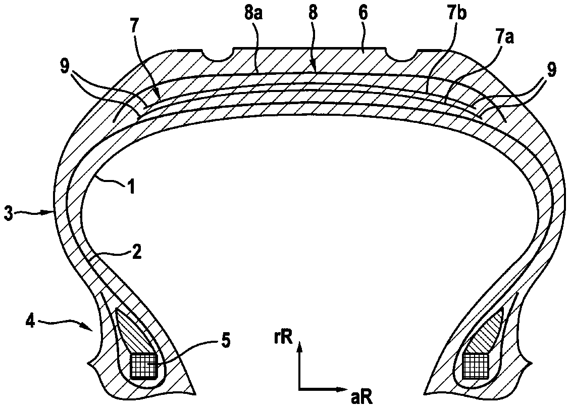
[0029] FIG. 1 shows a cross section through a pneumatic vehicle tire, FIG. 2 shows a cross section through the belt and the belt bandage of the pneumatic vehicle tire of FIG. 1.
[0030] FIG. 1 shows a cross section through a pneumatic vehicle tire for a passenger car, whereas FIG. 2 shows a cross section through the belt and the belt-covering belt bandage of the pneumatic vehicle tire of FIG. 1. Both figures are described together below. The essential components from which the depicted pneumatic vehicle tire is composed are a largely air-impermeable inner layer 1, a carcass 2 which conventionally reaches from the region of the crown of the pneumatic vehicle tire over the sidewalls 3 into the bead regions 4 and is anchored there by wrapping around high-tensile bead cores 5, a profiled tread 6 located radially above the carcass 2 and a belt 7 arranged between the tread 6 and the carcass 2 and comprising two belt plies 7 a, 7 b which is radially outwardly covered by a belt bandage 8 which comprises a single belt bandage ply 8a. The belt bandage ply 8a covers the belt along with its belt edges 9. The belt bandage ply 8 has strengthening elements (not shown) which are wound parallel and approximately in the circumferential direction of the pneumatic vehicle tire along its axial width.
[0031] The belt bandage ply 8a consists of three sections arranged next to one another: a central section 10 and in each case a lateral section 11, 12 adjoining the central section 10. The belt bandage ply 8a thus has the construction 1-1-1. The two lateral sections 11, 12 are thus arranged without overlapping with the central section 10. The end 13 of the lateral sections that points in each case toward the central section 10 in each case has a distance 14 of 5 mm-15 mm from the closest outer end of the widest belt ply 15, where the distance 14 is measured in the axial direction aR. The strengthening elements in the central section 10 have the construction x1 and the strengthening elements in the two lateral sections 11, 12 have the construction x2, with all the strengthening elements of the belt bandage ply 8a consisting of the same material, of PA6.6. The total fineness of each strengthening element is 940 dtex. The construction of each strengthening element in the lateral sections 11, 12 is 470 dtex x2 and the construction of each strengthening element in the central section 10 is 940 dtex x1. By virtue of the different construction of the strengthening elements in the central section 10 with respect to the lateral section 11, 12, the result is a diameter of the strengthening element in the lateral section 11, 12 of 0.40 mm and in the central section 10 of 0.30 mm. The strengthening elements are arranged in the lateral section 11, 12 in a density of 130 epdm and in the central section 10 with a density of 120 epdm. "epdm" stands for ends per decimeter and describes the density in which the strengthening elements are arranged in the reinforcing ply.
LIST OF REFERENCE SIGNS
[0032] (Part of the description)
[0033] 1 Inner layer
[0034] 2 1Carcass
[0035] 3 Sidewall
[0036] 4 Bead region
[0037] 5 Bead core
[0038] 6 Tread
[0039] 7 Belt
[0040] 7a1st Belt ply
[0041] 7b2nd Belt ply
[0042] 8 Belt bandage
[0043] 8a Belt bandage ply
[0044] 9 Belt edge
[0045] 10 Central section
[0046] 11 Lateral section
[0047] 12 Lateral section
[0048] 13 End of the lateral section
[0049] 14 Distance
[0050] 15 End of the widest belt ply
[0051] rR Radial direction
[0052] aR Axial direction
* * * * *
D00000
D00001
XML
uspto.report is an independent third-party trademark research tool that is not affiliated, endorsed, or sponsored by the United States Patent and Trademark Office (USPTO) or any other governmental organization. The information provided by uspto.report is based on publicly available data at the time of writing and is intended for informational purposes only.
While we strive to provide accurate and up-to-date information, we do not guarantee the accuracy, completeness, reliability, or suitability of the information displayed on this site. The use of this site is at your own risk. Any reliance you place on such information is therefore strictly at your own risk.
All official trademark data, including owner information, should be verified by visiting the official USPTO website at www.uspto.gov. This site is not intended to replace professional legal advice and should not be used as a substitute for consulting with a legal professional who is knowledgeable about trademark law.