Droplet Ejectors To Draw Fluids Through Microfluidic Networks
LAHMANN; John ; et al.
U.S. patent application number 17/046126 was filed with the patent office on 2021-02-04 for droplet ejectors to draw fluids through microfluidic networks. The applicant listed for this patent is HEWLETT-PACKARD DEVELOPMENT COMPANY, L.P.. Invention is credited to Silam J CHOY, Pavel KORNILOVICH, John LAHMANN.
| Application Number | 20210031188 17/046126 |
| Document ID | / |
| Family ID | 1000005166090 |
| Filed Date | 2021-02-04 |


| United States Patent Application | 20210031188 |
| Kind Code | A1 |
| LAHMANN; John ; et al. | February 4, 2021 |
DROPLET EJECTORS TO DRAW FLUIDS THROUGH MICROFLUIDIC NETWORKS
Abstract
An example device includes a chamber to receive a fluid, a first channel in communication with the chamber, a second channel in communication with the chamber, a target microfluidic network at the second channel, a first droplet ejector positioned at the first channel to draw a first portion of fluid through the first channel, and a second droplet ejector positioned at the second channel downstream of the target microfluidic network. The second droplet ejector is to draw a second portion of fluid through the second channel and into the target microfluidic network.
| Inventors: | LAHMANN; John; (Corvallis, OR) ; KORNILOVICH; Pavel; (Corvallis, OR) ; CHOY; Silam J; (Corvallis, OR) | ||||||||||
| Applicant: |
|
||||||||||
|---|---|---|---|---|---|---|---|---|---|---|---|
| Family ID: | 1000005166090 | ||||||||||
| Appl. No.: | 17/046126 | ||||||||||
| Filed: | November 22, 2018 | ||||||||||
| PCT Filed: | November 22, 2018 | ||||||||||
| PCT NO: | PCT/US2018/062366 | ||||||||||
| 371 Date: | October 8, 2020 |
Related U.S. Patent Documents
| Application Number | Filing Date | Patent Number | ||
|---|---|---|---|---|
| PCT/US2018/029169 | Apr 24, 2018 | |||
| 17046126 | ||||
| PCT/US2018/042416 | Jul 17, 2018 | |||
| PCT/US2018/029169 | ||||
| PCT/US2018/042411 | Jul 17, 2018 | |||
| PCT/US2018/042416 | ||||
| PCT/US2018/042408 | Jul 17, 2018 | |||
| PCT/US2018/042411 | ||||
| Current U.S. Class: | 1/1 |
| Current CPC Class: | B01L 3/502715 20130101; B01L 3/50273 20130101; B01L 2200/027 20130101; B01L 2400/0406 20130101 |
| International Class: | B01L 3/00 20060101 B01L003/00 |
Claims
1. A device comprising: a chamber to receive a fluid; a first channel in communication with the chamber; a second channel in communication with the chamber; a target microfluidic network at the second channel; a first droplet ejector positioned at the first channel to draw a first portion of fluid through the first channel; and a second droplet ejector positioned at the second channel downstream of the target microfluidic network, the second droplet ejector to draw a second portion of fluid through the second channel and into the target microfluidic network.
2. The device of claim 1, wherein the first droplet ejector provides capillary action to resist backflow of the first portion of fluid into the second channel.
3. The device of claim 1, wherein the target microfluidic network is to perform a nucleic acid amplification process.
4. The device of claim 3, further comprising a magnet positioned in the chamber.
5. The device of claim 1, wherein the first droplet ejector and the second droplet ejector are positioned to eject droplets of fluid to a waste area.
6. The device of claim 1, further comprising a third droplet ejector positioned to eject droplets of the fluid into the chamber.
7. The device of claim 6, wherein the first droplet ejector, the second droplet ejector, and the third droplet ejector are disposed on a same semiconductor substrate.
8. A method comprising: ejecting droplets of fluid with a first droplet ejector positioned at a first channel to draw from a chamber a first portion of fluid through the first channel; ejecting droplets of fluid with a second droplet ejector positioned at a second channel to draw from the chamber a second portion of fluid through the second channel and into a target microfluidic network positioned upstream of the second droplet ejector; and performing an analytical process with fluid at the target microfluidic network.
9. The method of claim 8, further comprising providing capillary action using the first droplet ejector to resist backflow of the first portion of the fluid into the second channel.
10. The method of claim 8, wherein performing the analytical process comprises performing a nucleic acid amplification process.
11. The method of claim 10, wherein the first portion of fluid comprises waste from a lysis buffer or a wash buffer, and wherein the second portion of fluid comprises eluted nucleic acid material.
12. The method of claim 8, wherein ejecting droplets of fluid with the first and second droplet ejectors comprises ejecting droplets of fluid into a waste area.
13. The method of claim 8, further comprising ejecting droplets of fluid with a third droplet ejector into the chamber.
14. The method of claim 8, further comprising performing an initial step of the analytical process with fluid in the chamber after ejecting droplets of fluid with the first droplet ejector and before ejecting droplets of fluid with the second droplet ejector.
15. A device comprising: a chamber to receive a fluid; a first channel communicating with the chamber; a first droplet ejector at a downstream end of the first channel; a second channel communicating with the chamber; a target microfluidic network communicating with the second channel, the target microfluidic network to perform an analytical process; a second droplet ejector at a downstream end of the second channel and downstream of the target microfluidic network; and a signal interface electrically connected to the first and second droplet ejectors to receive a signal to eject droplets of fluid with the first and second droplet ejectors to draw fluid from the chamber and into a target microfluidic network.
Description
BACKGROUND
[0001] Microfluidic systems may be used to perform a variety of chemical, biological, and biochemical processes, such as nucleic acid testing, Delivery of reagents to a process site may be accomplished in a variety of ways. In one type of system, reagents are dispensed to a target medium and may be wicked to a reaction chamber or other process site.
BRIEF DESCRIPTION OF THE DRAWINGS
[0002] FIG. 1 is a schematic diagram of an example device that uses droplet ejection to convey fluid with respect to a microfluidic network.
[0003] FIG. 2 is a schematic diagram of an example device that uses droplet ejection to convey fluid with respect to a microfluidic network that implements a nucleic acid testing process.
[0004] FIG. 3 is a schematic perspective diagram of a substrate that carries droplet ejectors to convey fluid with respect to a microfluidic network.
[0005] FIG. 4 is a schematic diagram of another example device that uses droplet ejection to convey fluid with respect to a microfluidic network that implements a nucleic acid testing process.
[0006] FIG. 5 is a schematic diagram of an example device that uses droplet ejection to convey fluid with respect to a plurality of parallel microfluidic networks.
[0007] FIG. 6 is a flowchart of an example method that uses droplet ejection to convey fluid with respect to a microfluidic network.
[0008] FIG. 7 is a flowchart of an example method for nucleic acid testing that uses droplet ejection to convey fluid with respect to a microfluidic network.
DETAILED DESCRIPTION
[0009] Dispensing of reagents to a target medium may include using droplet ejectors to eject fluid into microfluidic channels at the target medium. Flow of fluid within such microfluidic channels may then be controlled by pumps, valves, and other mechanisms to achieve a process implemented by the target medium. This kind of system is complex, in that operation of different types of fluid control elements (e.g., valves, pumps, etc.) needs to be coordinated. Further, backflow prevention often requires additional complexity and components, such as valves, which may also require coordinated control.
[0010] To reduce the need for such fluid control components and provide for simplified control of a microfluidic analytical process, such as a nucleic acid testing process, a droplet ejector or an array thereof is used to create negative pressure to draw a fluid, such as a reactant or intermediate reaction product, from a mesofluidic chamber to a particular target, such as a waste area or a microfluidic network for nucleic acid amplification.
[0011] Multiple droplet ejectors are used to selectively draw fluid from the mesofluidic chamber into different targets. Multiple droplet ejectors may be situated at the ends of branched channels that originate at the mesofluidic chamber. A selected droplet ejector is activated to draw fluid through the respective channel towards the respective target. As such, distinct fluid paths may be activated by driving a respective droplet ejector. Fluid in other channels is prevented from back flowing into a selected channel because inactive droplet ejectors provide sufficient negative pressure due to capillary action in the ejector nozzles to balance the negative pressure of the active ejectors. A wide variety of analytical processes, such as nucleic acid testing processes, may thus be performed using different fluid flow sequences that may be controlled without the need for valves or other mechanisms.
[0012] In the examples, the device comprises a chamber to receive a fluid; a first channel in communication with the chamber; a second channel in communication with the chamber; a target microfluidic network at the second channel; a first droplet ejector; and a second droplet ejector.
[0013] The first droplet ejector is positioned at the first channel to draw a first portion of fluid through the first channel. The second droplet ejector is positioned at the second channel downstream of the target microfluidic network and to draw a second portion of fluid through the second channel and into the target microfluidic network.
[0014] The first droplet ejector can provide capillary action to resist backflow of the first portion of fluid into the second channel.
[0015] The target microfluidic network can perform a nucleic acid amplification process.
[0016] The device can further include a magnet positioned in the chamber.
[0017] The first droplet ejector and the second droplet ejector can be positioned to eject droplets of fluid to a waste area.
[0018] The device can further include a third droplet ejector positioned to eject droplets of the fluid into the chamber.
[0019] The first droplet ejector, the second droplet ejector, and the third droplet ejector can be disposed on a same semiconductor substrate.
[0020] In some examples, the device comprises a chamber to receive a fluid; a first channel communicating with the chamber; a first droplet ejector at a downstream end of the first channel; a second channel communicating with the chamber; a target microfluidic network communicating with the second channel; and a second droplet ejector at a downstream end of the second channel and downstream of the target microfluidic network. The target microfluidic network is to perform an analytical process. The device further includes a signal interface electrically connected to the first and second droplet ejectors to receive a signal to eject droplets of fluid with the first and second droplet ejectors to draw fluid from the chamber and into a target microfluidic network.
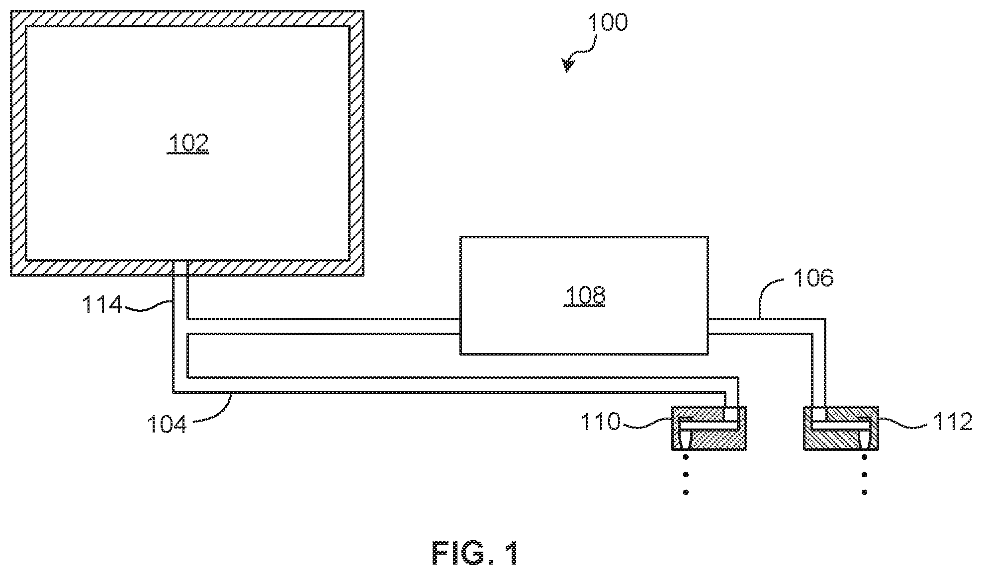
[0021] FIG. 1 shows an example device 100 that uses droplet ejection to convey fluid to and from a microfluidic network that may implement a nucleic acid testing process.
[0022] The device 100 includes a chamber 102, a first channel 104 in fluid communication with the chamber 102, a second channel 106 in fluid communication with the chamber 102, a target microfluidic network 108 at the second channel 106, a first droplet ejector 110 positioned at the first channel 104, and a second droplet ejector 112 positioned at the second channel 106.
[0023] The chamber 102 is to receive and contain a fluid. The chamber 102 may be mesofluidic in scale relative to the channels 104, 106, target microfluidic network 108, and droplet ejectors 110, 112, which are microfluidic in scale. The chamber 102 may be provided with a fluid or a sequence of fluids. A sequence of fluids may be provided by controlling fluid flow into the chamber 102 or by performing a reaction in the chamber 102. The chamber 102 may be vented to allow inflow of ambient air as fluid is drawn from the chamber 102.
[0024] The fluid provided to the chamber 102 may be a reagent, such as a chemical solution, a sample (e.g., a deoxyribonucleic acid or DNA sample, a ribonucleic acid or RNA sample, etc.), or other material. The term "fluid" is used herein to denote a material that may be jetted, such as aqueous solutions, suspensions, solvent solutions (e.g., alcohol-based solvent solutions), oil-based solutions, or other materials.
[0025] The first and second channels 104, 106 may originate at the chamber 102 or may branch from a common channel 114 that originates at the chamber 102. Irrespective of the specific structure of the first and second channels 104, 106, the first and second channels 104, 106 are capable of communicating fluid from the chamber 102. The channels 104, 106, 114 may be primed with fluid to communicate negative pressure from the droplet ejectors 110, 112 to the chamber 102. The priming fluid may include a drive fluid that is not used by the process implemented by the target microfluidic network 108 or a working fluid that is used by the target microfluidic network 108. A channel 104, 106, 114 may be preloaded with any number and sequence of slugs of drive and working fluids.
[0026] The first and second droplet ejectors 110, 112 may be formed at a substrate and such a substrate may have multiple layers. The substrate may include silicon, glass, photoresist (e.g., SU-8), or similar materials. A droplet ejector 110, 112 may include a jet element, such as a resistive heater, a piezoelectric element, or similar device that may implement inkjet droplet jetting techniques, such as thermal inkjet (TIJ) jetting. The jet element is controllable to draw fluid from the respective channel 104, 106 to jet fluid droplets out an orifice. An array having any number of droplet ejectors 110, 112 may be provided to a respective channel 104, 106.
[0027] The first droplet ejector 110 may be positioned at an end of the first channel 104 opposite the chamber 102. The first droplet ejector 110 may be aimed towards a waste receptible. When driven, the first droplet ejector 110 draws fluid from the chamber 102, through the common channel 114, and through the first channel 104 by low pressure generated by droplet ejection.
[0028] The second droplet ejector 112 is positioned at the second channel 106 downstream of the target microfluidic network 108. The second droplet ejector 112 may be positioned at an end of the second channel 106, such that the target microfluidic network 108 is between the chamber 102 and the second droplet ejector 112. When driven, the second droplet ejector 112 draws fluid from the chamber 102, through the common channel 114, and through the second channel 106 and into the target microfluidic network 108 by low pressure generated by droplet ejection.
[0029] The first droplet ejector 110 may provide capillary action to resist backflow of fluid from the first channel 104 into the second channel 106. That is, when the second droplet ejector 112 is driven and the first droplet ejector 110 is not driven, resistance at the first droplet ejector 110 due to capillary action may prevent fluid in the first channel 104 from being drawn back into the chamber 102.
[0030] The target microfluidic network 108 may include a passive component, such as a network of microfluidic channels, which may be made of silicon, silicon oxide, photoresist, polydimethylsiloxane (PDMS), cyclic olefin copolymer (COC), other plastics, glass, or other materials that may be made using micro-fabrication technologies. The target microfluidic network 108 may contain a solid compound to interact with fluid delivered by the second channel 106. A solid compound may be solid in bulk, may be a powder or particulate, may be integrated into a fibrous material, or similar.
[0031] The target microfluidic network 108 may include an active component. Examples of active components include a pump, sensor, mixing chamber, channel, heater, reaction chamber, droplet ejector, or similar component to perform further action on fluid delivered by the second channel 106.
[0032] In various examples, the target microfluidic network 108 includes microfluidic structure to implement a nucleic acid testing process, such as process that uses nucleic acid amplification (NAT), such as polymerase chain reaction (FOR), real-time or quantitative polymerase chain reaction (qPCR), reverse transcription polymerase chain reaction (RT-PCR), loop mediated isothermal amplification (LAMP), and similar.
[0033] In operation, the first droplet ejector 110 is driven to draw a first portion of fluid in the chamber 102 through the first channel 104. The first portion of fluid may include, for example, waste generated by reagents for nucleic acid extraction (e.g., lysis buffer) and washing of a nucleic acid sample provided to the chamber 102. As such, the first droplet ejector 110 may be used to eject waste fluid from an initial step of a process that takes place at the chamber 102. The second droplet ejector 112 is then driven to draw a second portion of fluid through the second channel 106 and into the target microfluidic network 108. The second portion of fluid may include an elution buffer and a nucleic acid sequence of interest as eluted from the prepared sample. The second droplet ejector 112 may thereby draw fluid for the nucleic acid testing process implemented by the target microfluidic network 108 to complete the process.
[0034] Fluid movement through the device 100 may be controlled by the droplet ejectors 110, 112 without the need for other active components, such as valves, for isolation of fluid having different properties or contents. Further, back flow of fluid from one channel 104, 106 to another channel 104, 106 may be prevented by capillary resistance provided by the droplet ejectors 110, 112. As such, a nucleic acid testing process may be performed at a target microfluidic network 108 with reduced risk of contamination by waste products.
[0035] FIG. 2 shows an example device 200. Features and aspects of the other devices and systems described herein may be used with the device 200 and vice versa. Like reference numerals denote like elements and description of like elements is not repeated here.
[0036] The device 200 includes a mesofluidic chamber 102, a first channel 202 communicating with the chamber 102, a first array of droplet ejectors 204, a second channel 206 communicating with the chamber 102, a target microfluidic network 208 communicating with the second channel 206, and second array of droplet ejectors 210.
[0037] The first array of droplet ejectors 204 is positioned at a downstream end of the first channel 202, which may communicate with the chamber 102 via a common upstream channel 212. The first array of droplet ejectors 204 may be positioned to eject fluid into a waste area 214, such as a waste receptible. The first channel 202 may be primed with a drive fluid prior to operation. A drive fluid reservoir may be positioned between the first array of droplet ejectors 204 and the first channel 202 to supply a volume of drive fluid.
[0038] The second array of droplet ejectors 210 is positioned at a downstream end of the second channel 206 at a position downstream of the target microfluidic network 208. The second array of droplet ejectors 210 may be positioned to eject fluid into the waste area 214. The first array of droplet ejectors 204 and the second array of droplet ejectors 210 may be disposed on the same semiconductor substrate 215. Alternatively, the droplet ejectors 204, 210 may be disposed on different semiconductor substrates that may be physically joined by, for example, being molded into a single flat package (e.g., semiconductor slivers that are epoxy-molded together). The second channel 206 may be primed with a drive fluid or a working fluid prior to operation. A drive/working fluid reservoir may be positioned between the second array of droplet ejectors 210 and the second channel 202 to supply a volume of drive/working fluid. The common upstream channel 212 may be primed with a drive fluid or a working fluid prior to operation.
[0039] The target microfluidic network 208 communicates the common upstream channel 212 to the second channel 206. That is, the common upstream channel 212 feeds fluid to the target microfluidic network 208, which outputs fluid to the second channel 206 as drawn by the low pressure induced by the second array of droplet ejectors 210 when driven.
[0040] The common upstream channel 212 provides a common vent path, so that fluid flow may be split downstream of the common upstream channel 212. That is, capillary action provided by the first and second arrays of droplet ejectors 204, 210 when inactive cooperates with venting through the common upstream channel 212, so that fluid in the first and second channels 202, 206 may be independently flowed in a controllable manner without undue backflow.
[0041] The target microfluidic network 208 is to perform an analytical process, such as a nucleic acid testing process. The target microfluidic network 208 may be preloaded with freeze dried FOR master mix. In other examples, a freeze dried material may be provided for reconstitution in the chamber 102. Such material may be reconstituted by fluid jetted into the chamber 102. For example, a lysis buffer, and enzyme-based lysis butter, or similar material may be provided to the chamber 102 for reconstitution.
[0042] The device 200 further includes a driving signal interface 216 electrically connected to the first and second arrays of droplet ejectors 204, 210. The driving signal interface 216 may include an electrical contact that is electrically connected to a resistive heater or other driving element of a droplet ejector. The driving signal interface 216 is to receive a signal to eject droplets of fluid with the first and second arrays of droplet ejectors 204, 210, so as to selectively draw fluid from the chamber 102 and into a target microfluidic network 208.
[0043] The device 200 may further include an analysis signal interface 218 at the target microfluidic network 208. The analysis signal interface 218 may include an electrical contact to communicate a signal relevant for the analytical process performed. For example, the analysis signal interface 218 may communicate a signal that drives a heater of a PCR process or other NAT process that uses thermal cycling. The analysis signal interface 218 may communicate an output signal from the target microfluidic network 208, such as an output electrode voltage.
[0044] The device 200 may further include a third array of droplet ejectors 220 positioned to eject droplets of the fluid into the chamber 102. The third array of droplet ejectors 220 may include a fluid reservoir preloaded with a fluid, such as a wash buffer.
[0045] The device 200 may further include a fourth array of droplet ejectors 222 positioned to eject droplets of the fluid into the chamber 102. The fourth array of droplet ejectors 222 may include a fluid reservoir preloaded with a fluid, such as an elution buffer. In other examples, a PCR master mix solution is provided to a fluid reservoir that feeds the fourth array of droplet ejectors 222, rather than providing a dried master mix reconstitution at the target microfluidic network 208.
[0046] The third and fourth arrays of droplet ejectors 220, 222 may be disposed on the same substrate 215 or on different substrates.
[0047] The driving signal interface 216 may also be electrically connected to the third and fourth arrays of droplet ejectors 220, 222 to control the driving of third and fourth arrays of droplet ejectors 220, 222.
[0048] The chamber 102 may be temporarily sealed by a frangible seal 224, such as a polymer membrane, a foil seal, or similar. The seal 224 may be broken by insertion of a sample-bearing element 226, such as a swab, that introduces nucleic acid sample to the chamber 102. Further, a lysis buffer may be introduced with the sample-bearing element 226 or otherwise via the opening created into the chamber 102 by the sample-bearing element 226 breaking the seal 224. An auxiliary chamber 228 may be provided at the seal 224 to contain the lysis buffer prior to the seal 224 being broken. Further, the seal 224 when broken may provide venting to the chamber 102 and the common upstream channel 212.
[0049] The chamber 102 may further include a funnel 230 that narrows to the common upstream channel 212. A sample preparation volume 232 may exist in the chamber 102 and further may be located within the funnel 230. A magnet 234 may be provided in the sample preparation volume 232 to assist in sample preparation. The chamber 102 provides a mesofluidic interface between human-scale fluidics, such as the sample-bearing element 226, seal 224, source fluids lysis buffer, wash buffer, and elution butter), and microfluidic elements, such as the channels 202, 206, 212 and target microfluidic network 208.
[0050] In an example of operation of the device 200, a DNA/RNA sample is collected on a swab 226 and mixed with a lysis buffer at the auxiliary chamber 228. The seal 224 is then broken by forcing the swab 226 against the seal 224. The mixture of the lysis buffer and sample is introduced into the chamber 102 through the broken seal 224, which may be assisted by orienting the device 200 so that the auxiliary chamber 228 is above the main chamber 102 with respect to gravity G. The mixture collects in the sample preparation zone 232.
[0051] The first array of droplet ejectors 204 is then driven by a signal provided at the driving signal interface 216 to draw the mixture of the lysis buffer and sample material through the common upstream channel 212 and the first channel 202 towards the waste area 214. The magnet 234 retains DNA/RNA collected at or near its surface.
[0052] Then, the third array of droplet ejectors 220 is driven by a signal provided at the driving signal interface 216 to eject a wash buffer to the sample preparation zone 232. The wash product at the sample preparation zone 232 not retained by the magnet 234 is drawn out of the chamber 102 by driving the first array of droplet ejectors 204 to eject fluid droplets to the waste area 214.
[0053] After cleaning, the fourth array of droplet ejectors 222 is driven by a signal provided at the driving signal interface 216 to eject an elution buffer to the sample preparation zone 232 to elute DNA/RNA from the surface of the magnet 234.
[0054] The signal that drives the first array of droplet ejectors 204 is stopped, and the second array of droplet ejectors 210 is then driven by a signal provided at the driving signal interface 216 to draw the fluid containing the eluted DNA/RNA into through the common upstream channel 212 and into the target microfluidic network 208. Backflow of waste remaining within the first channel 202 is prevented by capillary resistance provided by the first array of droplet ejectors 204.
[0055] The fluid containing the eluted DNA/RNA and drawn into the target microfluidic network 208 by the second array of droplet ejectors 210 reconstitutes FOR master mix preloaded at the target microfluidic network 208. The target microfluidic network 208 is controlled via the analysis signal interface 218 to cycle temperature and/or provide other input/output to effect the DNA/RNA amplification process.
[0056] In other examples, the magnet 234 is embedded in or attached to an inner wall of the funnel 230. As such, a reagent may be made to contact or not contact the magnet, depending on relative positions of the magnet and the respective droplet ejector 220, 222. For example, magnetic material may be placed in the path of ejection of a droplet ejector 220, 222 and outside a path of ejection of another droplet ejector 220, 222.
[0057] FIG. 3 shows an example substrate 215 that carries droplet ejectors. The substrate 215 may be a semiconductor substrate and may include silicon, glass, photoresist (e.g., SU-8), or similar materials.
[0058] Droplet ejector orifices 300 may be arranged along the substrate 215 in a linear or rectangular arrangement. Subsets of droplet ejector orifices 300 may communicate with different fluid reservoirs, so as to form arrays of droplet ejectors, such as the arrays of droplet ejectors 204, 210, 220, 222.
[0059] A heater 302 may be provided at the substrate 215 adjacent an array of droplet ejectors 222 used for an elution buffer, so that the elution buffer may be preheated. The heater 302 may include a resistive heating element.
[0060] A signal interface 304 may be connected to the substrate 215 to provide an ejector driving signal, a heater power signal, or similar.
[0061] FIG. 4 shows an example device 400. Features and aspects of the other devices and systems described herein may be used with the device 400 and vice versa. Like reference numerals denote like elements and description of like elements is not repeated here.
[0062] A vent port 402 may be provided to the chamber 102 to vent the chamber 102 independently of the introduction of a sample by a sample-bearing element 226.
[0063] An auxiliary chamber 228 to introduce the lysis buffer and sample may be provided with an array of droplet ejectors 404. The array of droplet ejectors 404 may be driven by a signal provided at a driving signal interface 216 to eject droplets of a mixture of the sample with the lysis buffer into the chamber 102. That is, the mixture of the sample with the lysis buffer is controllably ejected into the chamber 102 rather than being manually introduced. The array of droplet ejectors 404 may be provided to the same substrate 215 as other arrays of droplet ejectors 204, 210, 220, 222.
[0064] A magnet 406 may be provided at a common upstream channel 212 through which fluid is drawn from the chamber 102. For example, the magnet 406 may be positioned outside the channel 212 to provide a magnetic field to fluid inside the channel 212. A lysis buffer ejected into the chamber 102 may include paramagnetic beads that interact with the magnetic field and collect near the magnet 406. Sample concentration may thus occur at a sample preparation volume 408 of the common upstream channel 212 in the vicinity of the magnet 406.
[0065] FIG. 5 shows an example device 500. Features and aspects of the other devices and systems described herein may be used with the device 500 and vice versa. Like reference numerals denote like elements and description of like elements is not repeated here.
[0066] The device 500 includes a chamber 502 that is fed droplets by a plurality of input droplet ejectors 504. A given input droplet ejector 504 may be provided fluid by a fluid reservoir, which may be preloaded or loaded at time of use with a reagent, sample, or similar.
[0067] The device 500 further includes a plurality of output droplet ejectors 506 to draw fluid through the device 500, The plurality of output droplet ejectors 506 may eject droplets to a waste area 508. A given output droplet ejector 506 may be provided fluid by a microfluidic channel 510.
[0068] The device 500 further includes a plurality of target microfluidic networks 512. A given target microfluidic network 512 outputs fluid to a respective microfluidic channel 510.
[0069] The chamber 502 feeds a common upstream channel 514 that branches to feed fluid to the target microfluidic networks 512. Control of distribution of fluid to the microfluidic networks 512 from the chamber 502 is dictated by driving the output droplet ejectors 506. A target microfluidic network 512 that is to receive fluid has its respective output droplet ejector 506 driven. Backflow from waste or from another target microfluidic network 512 is prevented by capillary action provided by a nozzle of a respective undriven output droplet ejector 506.
[0070] A waste microfluidic channel 516 may bypass the target microfluidic networks 512 to eject waste product directly to the waste area 508.
[0071] The target microfluidic networks 512 may implement a parallel array of nucleic acid testing processes for conducting nucleic acid amplification/detection. The chamber 502 may provide for mixing, an initial reaction step, or similar process in advance of the process implemented at the target microfluidic networks 512.
[0072] The plurality of input droplet ejectors 504 and the plurality of output droplet ejectors 506 may be provided at the same semiconductor substrate 518, Alternatively, multiple substrates may be used and such substrates may be provided in a unitary package.
[0073] In some examples, the devices described herein can be used with a method for performing an analytical process. An example method comprises ejecting droplets of fluid with a first droplet ejector positioned at a first channel to draw from a chamber a first portion of fluid through the first channel; ejecting droplets of fluid with a second droplet ejector positioned at a second channel to draw from the chamber a second portion of fluid through the second channel and into a target microfluidic network positioned upstream of the second droplet ejector; and performing an analytical process with fluid at the target microfluidic network.
[0074] The method can further include providing capillary action using the first droplet ejector to resist backflow of the first portion of the fluid into the second channel.
[0075] Performing the analytical process can include performing a nucleic acid amplification process.
[0076] The first portion of fluid can include waste from a lysis buffer or a wash buffer, and the second portion of fluid can include eluted nucleic acid material.
[0077] Ejecting droplets of fluid with the first and second droplet ejectors can include ejecting droplets of fluid into a waste area.
[0078] The method can further include ejecting droplets of fluid with a third droplet ejector into the chamber.
[0079] The method can further include performing an initial step of the analytical process with fluid in the chamber after ejecting droplets of fluid with the first droplet ejector and before ejecting droplets of fluid with the second droplet ejector.
[0080] FIG. 6 shows an example method 600 for using droplet ejection to convey fluid with respect to a microfluidic network. The method 600 may be performed by any of the systems and devices described herein. The method starts at block 602 with a fluid located within a chamber.
[0081] At block 604, droplets of fluid are ejected by a first droplet ejector positioned at a first channel downstream of the chamber. Ejection of fluid droplets creates negative pressure in the first channel and such negative pressure acts to draw from a chamber a first portion of fluid through the first channel. The first portion of fluid may be used to wash or prepare a reagent in the chamber and may be drawn directly towards a waste area and ejected into the waste area by the first droplet ejector. The fluid ejected by the first droplet ejector may include fluid of the first portion or a drive fluid that was preloaded into the first droplet ejector and first channel.
[0082] At block 606, droplets of fluid are ejected with a second droplet ejector positioned at a second channel downstream of the chamber. Ejection of fluid droplets creates negative pressure in the second channel and such negative pressure acts to draw from the chamber a second portion of fluid through the second channel and into a target microfluidic network positioned upstream of the second droplet ejector. That is, a target microfluidic network is provided with fluid from an upstream chamber by operation of a downstream droplet ejector. The second portion of fluid may convey a sample, reagent, analyte, or similar material into the target microfluidic network. After serving its purpose in the target microfluidic network, the second portion of fluid may ultimately be ejected to a waste area by the second droplet ejector.
[0083] At block 608, an analytical process is performed with fluid at the target microfluidic network. The analytical process may include a nucleic acid testing that may use nucleic acid amplification. The method ends at block 610.
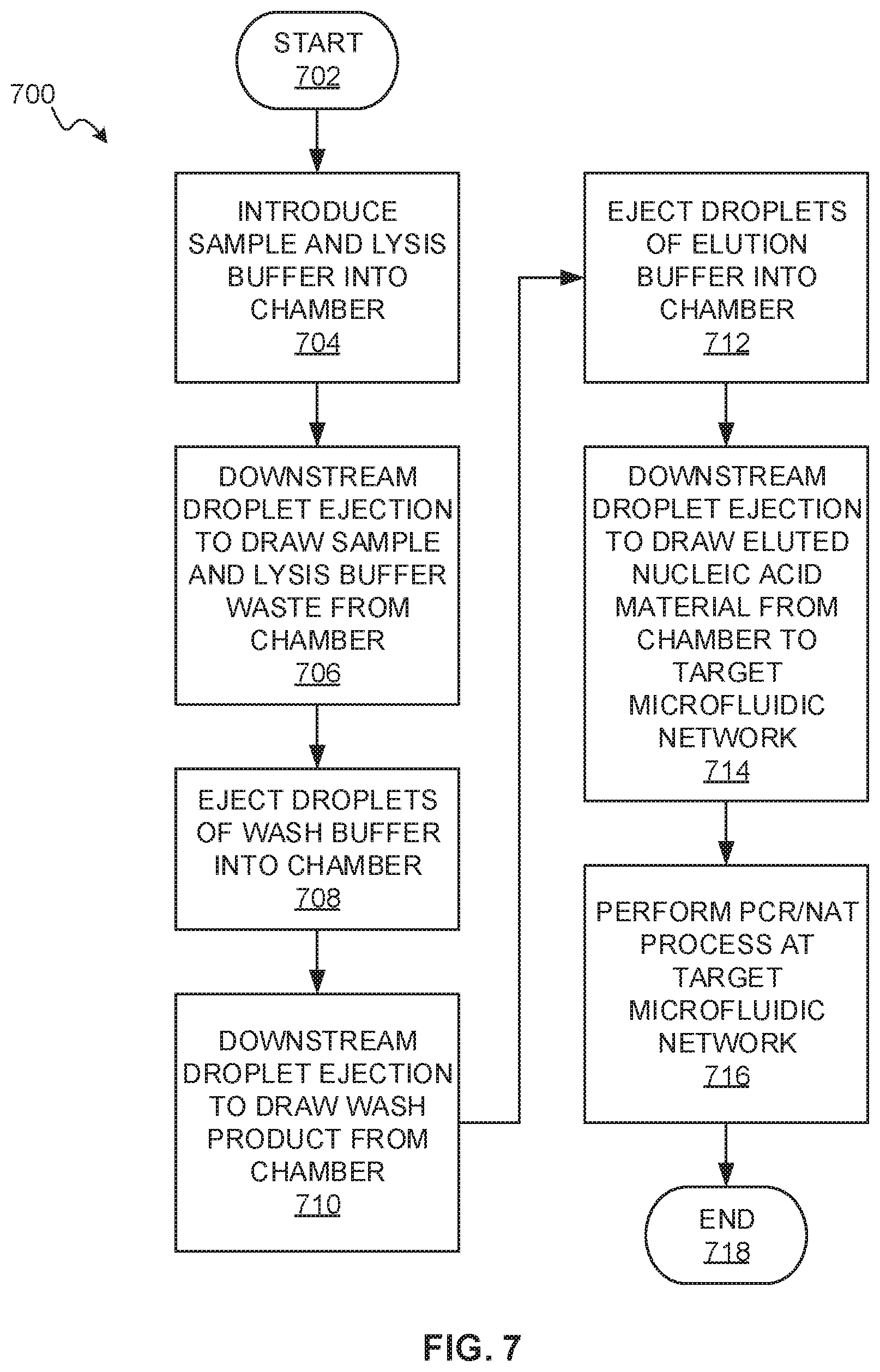
[0084] FIG. 7 is a flowchart of an example method 700 for nucleic acid testing, which uses a nucleic acid amplification process, such as PCR and others described herein. The method 700 may be performed by any of the systems and devices described herein. FIG. 2 may be referenced for example structure suitable for performing the method 700. The method starts at block 702.
[0085] At block 704, a DNA/RNA sample is introduced into a chamber. A lysis buffer may also be introduced into the chamber. This may be accomplished by manually inserting a sample-bearing swab into the chamber, which may include breaking a seal to introduce a lysis buffer, or by ejecting droplets of fluid containing the sample and lysis buffer into the chamber using a droplet ejector.
[0086] At block 706, a droplet ejector positioned downstream of the chamber is driven to draw the mixture of the lysis buffer and sample material from the chamber towards a waste area. A magnet in the chamber retains DNA/RNA material in the chamber.
[0087] At block 708, a wash buffer is introduced into the chamber by ejecting droplets of wash buffer into the chamber using a droplet ejector.
[0088] At block 710, a droplet ejector positioned downstream of the chamber is driven to draw the wash buffer product that is not retained by the magnet from the chamber towards a waste area.
[0089] At block 712, an elution buffer is introduced into the chamber by ejecting droplets of elution buffer into the chamber using a droplet ejector.
[0090] The action of the lysis buffer, wash buffer, and elution buffer within the chamber, at blocks 704, 708, 712, may individually or cooperatively be considered an initial step of nucleic acid testing process implemented by a target microfluidic network located downstream of the chamber.
[0091] At block 714, a droplet ejector positioned downstream of the chamber is driven to draw fluid containing DNA/RNA eluted from the surface of the magnet into a target microfluidic network. Backflow of waste from blocks 706 and 710 towards the target microfluidic network is prevented by capillary resistance provided by the respective droplet ejector.
[0092] At block 716, a DNA/RNA amplification process and nucleic acid testing process are performed at the target microfluidic network. This may include the fluid drawn at block 714 reconstituting a freeze-dried FOR master mix preloaded at the target microfluidic network, controlling a heater at the target microfluidic network to cycle temperature, and similar. The method ends at block 718.
[0093] It should be apparent from the above that complexity of microfluidic structures, such as a nucleic acid testing device, may be reduced by using droplet ejectors to draw reagents, samples, or other fluid through a microfluidic network that implements an analytical process. The complexity required by other fluid control elements (e.g., valves, positive pressure pumps, etc.) is avoided. Further, backflow is inherently prevented thereby avoiding the need for active valves to stop backflow. The complexity of nucleic acid testing, such as microfluidics for mixing a sample with several reagents as well as filtration, separation, heating, washing and other unit process steps, is reduced.
[0094] It should be recognized that features and aspects of the various examples provided above can be combined into further examples that also fall within the scope of the present disclosure. In addition, the figures are not to scale and may have size and shape exaggerated for illustrative purposes.
* * * * *
D00000
D00001
D00002
D00003
D00004
D00005
D00006
XML
uspto.report is an independent third-party trademark research tool that is not affiliated, endorsed, or sponsored by the United States Patent and Trademark Office (USPTO) or any other governmental organization. The information provided by uspto.report is based on publicly available data at the time of writing and is intended for informational purposes only.
While we strive to provide accurate and up-to-date information, we do not guarantee the accuracy, completeness, reliability, or suitability of the information displayed on this site. The use of this site is at your own risk. Any reliance you place on such information is therefore strictly at your own risk.
All official trademark data, including owner information, should be verified by visiting the official USPTO website at www.uspto.gov. This site is not intended to replace professional legal advice and should not be used as a substitute for consulting with a legal professional who is knowledgeable about trademark law.