Toy Vehicle Track Accessory
CAO; Kevin
U.S. patent application number 16/529871 was filed with the patent office on 2021-02-04 for toy vehicle track accessory. The applicant listed for this patent is Mattel, Inc.. Invention is credited to Kevin CAO.
| Application Number | 20210031118 16/529871 |
| Document ID | / |
| Family ID | 1000004273019 |
| Filed Date | 2021-02-04 |


| United States Patent Application | 20210031118 |
| Kind Code | A1 |
| CAO; Kevin | February 4, 2021 |
TOY VEHICLE TRACK ACCESSORY
Abstract
A toy vehicle track accessory comprising a main body having a first pathway, a second pathway, and a third pathway that bifurcates into the first and second pathways. A first track connector is pivotably coupled to the first pathway and is pivotable in a direction coplanar with the main body. A second track connector is pivotably coupled to the second pathway and is pivotable in a direction coplanar with the main body. A third track connector is pivotably coupled to the third pathway and is pivotable in a direction coplanar with the main body.
| Inventors: | CAO; Kevin; (Reseda, CA) | ||||||||||
| Applicant: |
|
||||||||||
|---|---|---|---|---|---|---|---|---|---|---|---|
| Family ID: | 1000004273019 | ||||||||||
| Appl. No.: | 16/529871 | ||||||||||
| Filed: | August 2, 2019 |
| Current U.S. Class: | 1/1 |
| Current CPC Class: | A63H 18/02 20130101 |
| International Class: | A63H 18/02 20060101 A63H018/02 |
Claims
1. A toy vehicle track accessory comprising: a main body defining a first pathway and a second pathway that converge into a third pathway, the first pathway having a first end with a first angular portion, the second pathway having a second end with a second angular portion, the third pathway having a third end with a third angular portion, wherein each of the first, second, and third angular portions have a convex edge with an interior angle of less than 180 degrees; a first track connector pivotably coupled to the first end, the first track connector pivotable in a direction coplanar with the main body and further including a protrusion configured to engage the first angular portion; a second track connector pivotably coupled to the second end, the second track connector pivotable in a direction coplanar with the main body and further including a protrusion configured to engage the second angular portion; and a third track connector pivotably coupled to the third end, the third track connector pivotable in a direction coplanar with the main body and further including a protrusion configured to engage the third angular portion.
2. The toy vehicle track accessory of claim 1, wherein the interior angles of the first, second, and third angular portions are the same.
3. The toy vehicle track accessory of claim 1, wherein: the interior angles of the first and second angular portions are the same; and the interior angle of the third angular portion is different from the interior angles of the first and second angular portions.
4. The toy vehicle track accessory of claim 1, wherein: the main body, first track connector, second track connector, and third track connector each include a pair of opposing track walls; and the track walls of the main body include widened sections sized to accommodate the track walls of the first, second, and third track connectors.
5. The toy vehicle track accessory of claim 1, wherein: the first pathway includes a first arcuate opening, the second pathway includes a second arcuate opening, and the third pathway includes a third arcuate opening; and the first track connector includes a projection that travels lengthwise along the first arcuate opening when the first track connector is pivoted, the second track connector includes a second projection that travels lengthwise along the second arcuate opening when the second track connector is pivoted, and the third track connector includes a third projection that travels lengthwise along the third arcuate opening when the third track connector is pivoted.
6. The toy vehicle track accessory of claim 1, wherein: the first pathway includes a pair of first arcuate openings, the second pathway includes a pair of second arcuate openings, and the third pathway includes a pair of third arcuate openings; and the first track connector includes a pair of first projections that travel lengthwise along the first arcuate openings when the first track connector is pivoted, the second track connector includes a pair of second projections that travel lengthwise along the second arcuate openings when the second track connector is pivoted, and the third track connector includes a pair of third projections that travel lengthwise along the third arcuate openings when the third track connector is pivoted.
7. A toy vehicle track accessory comprising: a main body including a first track wall on a first edge of the main body, a second track wall on a second edge of the main body opposite the first edge, and a divider between the first and second track walls, wherein the first track wall, second track wall, and divider collectively define a first pathway and a second pathway that converge into a third pathway; a pivotable first track connector extending from the first pathway, the first track connector including a semicircular portion positioned between the first track wall and divider; a pivotable second track connector extending from the second pathway, the second track connector including a semicircular portion positioned between the divider and the second track wall; and a pivotable third track connector extending from the third pathway, the third track connector including a semicircular portion positioned between the first track wall and the second track wall.
8. The toy vehicle track accessory of claim 7, wherein: the first pathway includes a first arcuate opening, the second pathway includes a second arcuate opening, and the third pathway includes a third arcuate opening; and the semicircular portion of the first track connector includes a projection that travels lengthwise along the first arcuate opening when the first track connector is pivoted, the semicircular portion of the second track connector includes a second projection that travels lengthwise along the second arcuate opening when the second track connector is pivoted, and the semicircular portion of the third track connector includes a third projection that travels lengthwise along the third arcuate opening when the third track connector is pivoted.
9. The toy vehicle track accessory of claim 7, wherein: the first pathway includes a pair of first arcuate openings, the second pathway includes a pair of second arcuate openings, and the third pathway includes a pair of third arcuate openings; and the semicircular portion of the first track connector includes a pair of first projections that travel lengthwise along the first arcuate openings when the first track connector is pivoted, the semicircular portion of the second track connector includes a pair of second projections that travel lengthwise along the second arcuate openings when the second track connector is pivoted, and the semicircular portion of the third track connector includes a pair of third projections that travel lengthwise along the third arcuate openings when the third track connector is pivoted.
10. The toy vehicle track accessory of claim 7, wherein: the first track connector, second track connector, and third track connector each include a pair of opposing connector track walls; and the first and second track walls of the main body include widened sections sized to accommodate the connector track walls of the first, second, and third track connectors.
11. The toy vehicle track accessory of claim 7, wherein the main body includes semicircular indentations sized to receive the semicircular portions of the first, second, and third track connectors.
12. The toy vehicle track accessory of claim 7, wherein: the main body includes a first angular portion between the first track wall and divider, a second angular portion between the divider and second track wall, and a third angular portion between the first track wall and second track wall; and each of the first, second, and third angular portions have a convex edge with an interior angle of less than 180 degrees.
13. The toy vehicle track accessory of claim 12, wherein: the first track connector includes a straight protrusion configured to abut the first angular portion; the second track connector includes a straight protrusion configured to abut the second angular portion; and the third track connector includes a straight protrusion configured to abut the third angular portion.
14. The toy vehicle track accessory of claim 12, wherein the interior angles of the first, second, and third angular portions are the same.
15. The toy vehicle track accessory of claim 12, wherein: the interior angles of the first and second angular portions are the same; and the interior angle of the third angular portion is different from the first and second angular portions.
16. A toy vehicle track accessory comprising: a main body comprising a first pathway, a second pathway, and a third pathway, wherein the third pathway bifurcates into the first and second pathways; a first track connector pivotably coupled to the first pathway, the first track connector pivotable in a direction coplanar with the main body; a second track connector pivotably coupled to the second pathway, the second track connector pivotable in a direction coplanar with the main body; and a third track connector pivotably coupled to the third pathway, the third track connector pivotable in a direction coplanar with the main body.
17. The toy vehicle track accessory of claim 16, wherein: the first pathway includes a first angular portion, the second pathway includes a second angular portion, and the third pathway includes a third angular portion, wherein each of the first, second, and third angular portions have a convex edge with an interior angle of less than 180 degrees; the first track connector includes a straight protrusion configured to abut the first angular portion, a center of the straight protrusion aligned proximate a vertex of the convex edge of the first angular portion; the second track connector includes a straight protrusion configured to abut the second angular portion, a center of the straight protrusion aligned proximate the vertex of the convex edge of the second angular portion; and the third track connector includes a straight protrusion configured to abut the third angular portion, a center of the straight protrusion aligned proximate the vertex of the convex edge of the third angular portion.
18. The toy vehicle track accessory of claim 16, wherein: the first pathway includes a pair of first arcuate openings, the second pathway includes a pair of second arcuate openings, and the third pathway includes a pair of third arcuate openings; and the first track connector includes a pair of first projections that travel lengthwise along the first arcuate openings when the first track connector is pivoted, the second track connector includes a pair of second projections that travel lengthwise along the second arcuate openings when the second track connector is pivoted, and the third track connector includes a pair of third projections that travel lengthwise along the third arcuate openings when the third track connector is pivoted.
19. The toy vehicle track accessory of claim 16, wherein: the main body, first track connector, second track connector, and third track connector each include a pair of opposing track walls; and the track walls of the main body include widened sections sized to accommodate the track walls of the first, second, and third track connectors.
20. The toy vehicle track accessory of claim 16, wherein: the first, second, and third track connectors each include a semicircular portion; and the main body includes semicircular indentations sized to receive the semicircular portions of the first, second, and third track connectors.
Description
FIELD OF THE INVENTION
[0001] This invention relates generally to tracks for toy vehicles, and in particular, to a track accessory for use with other track segments and toy vehicle track sets.
BACKGROUND
[0002] Toy vehicles with wheels that roll and spin freely with minimal friction have long been a source of entertainment for children of all ages. A variety of tracks and raceways have further been developed for use with such toy vehicles. The tracks and raceways may be a simple straight track or include variations such as curves, loops, and ramps. Additionally, track sets have been developed which allow a child to assemble individual track segments in different layouts and sequences to create different raceways. While a variety of shapes and geometries for individual track segments may be found in the art, there remains an opportunity to enhance a child's play experience by providing new and unique track segments and accessories that can be used when creating toy vehicle raceways.
BRIEF SUMMARY OF THE INVENTION
[0003] A track accessory that allows for the converging or diverging of track set pathways for toy vehicles is disclosed herein. In accordance with one or more embodiments of the present invention, the toy vehicle track accessory comprises a main body that defines a first toy vehicle pathway, a second toy vehicle pathway, and a third toy vehicle pathway. Depending on the direction in which a toy vehicle travels through the track accessory, the first and second pathways converge into the third pathway or in other instances, the third pathway bifurcates into the first and second pathways. A first track connector, a second track connector, and a third track connector are pivotably coupled to the first, second, and third pathways, respectively. The first, second, and third track connectors are each pivotable in a direction coplanar with the main body.
[0004] The first pathway has a first end with a first angular portion, the second pathway has a second end with a second angular portion, and the third pathway has a third end with a third angular portion. The first track connector includes a protrusion that is configured to engage the first angular portion. The center of the protrusion of the first track connector is aligned proximate the vertex of the first angular portion. The second track connector includes a protrusion configured to engage the second angular portion. The center of the protrusion of the second track connector is aligned proximate the vertex of the second angular portion. The third track connector includes a protrusion configured to engage the third angular portion. The center of the protrusion of the third track connector is aligned proximate the vertex of the third angular portion.
[0005] Each of the first, second, and third angular portions has a convex edge with an interior angle of less than 180 degrees. In one instance, the interior angles of the first, second, and third angular portions are the same. In another instance, the interior angles of the first and second angular portions are the same, but the interior angle of the third angular portion is different from the interior angles of the first and second angular portions. In yet another instance, the interior angles of the first, second, and third angular portions are all different.
[0006] In one or more embodiments, the first pathway includes a first arcuate opening, the second pathway includes a second arcuate opening, and the third pathway includes a third arcuate opening. The first track connector includes a projection that travels lengthwise along the first arcuate opening when the first track connector is pivoted. The second track connector includes a second projection that travels lengthwise along the second arcuate opening when the second track connector is pivoted. The third track connector includes a third projection that travels lengthwise along the third arcuate opening when the third track connector is pivoted.
[0007] In other embodiments, the first pathway includes a pair of first arcuate openings, the second pathway includes a pair of second arcuate openings, and the third pathway includes a pair of third arcuate openings. The first track connector includes a pair of first projections that travel lengthwise along the first arcuate openings when the first track connector is pivoted. The second track connector includes a pair of second projections that travel lengthwise along the second arcuate openings when the second track connector is pivoted. The third track connector includes a pair of third projections that travel lengthwise along the third arcuate openings when the third track connector is pivoted.
[0008] The main body, first track connector, second track connector, and third track connector may each include a pair of opposing track walls. In certain instances, the track walls of the main body include widened sections sized to accommodate the track walls of the first, second, and third track connectors. In one or more embodiments, the first, second, and third track connectors each include a semicircular portion. The main body includes semicircular indentations sized to receive the semicircular portions of the first, second, and third track connectors.
[0009] In accordance with other embodiments of the present invention, the toy vehicle track accessory comprises a main body including a first track wall on a first edge of the main body, a second track wall on a second edge of the main body opposite the first edge, and a divider between the first and second track walls. The first track wall, second track wall, and divider collectively define a first pathway and a second pathway that converge into a third pathway. A pivotable first track connector extends from the first pathway. The first track connector includes a semicircular portion positioned between the first track wall and divider. A pivotable second track connector extends from the second pathway. The second track connector includes a semicircular portion positioned between the divider and the second track wall. A pivotable third track connector extends from the third pathway. The third track connector includes a semicircular portion positioned between the first track wall and the second track wall.
[0010] Other objects, features, and advantages of the invention will become apparent from the following detailed description, taken in conjunction with the accompanying drawings, which illustrate, by way of example, the principles of the invention. It is to be understood, however, that the detailed description, drawings, and examples provided, while disclosing some embodiments, are given by way of illustration and not limitation. Many changes and modifications within the scope of the present invention may be made without departing from the spirit thereof, and the present invention includes all such modifications.
BRIEF DESCRIPTION OF THE DRAWINGS
[0011] Referring now to the drawings in which like reference numbers represent corresponding parts throughout:
[0012] FIG. 1 provides a top view of a toy vehicle track accessory, in accordance with an illustrative embodiment of the invention.
[0013] FIG. 2 provides a bottom view of the toy vehicle track accessory shown in FIG. 1, in accordance with an illustrative embodiment of the invention.
[0014] FIG. 3 provides a close-up view of a portion of the toy vehicle accessory shown in FIG. 1 where a track connector is pivoted, in accordance with an illustrative embodiment of the invention.
[0015] FIG. 4 provides a side perspective view of the toy vehicle accessory shown in FIG. 1 where the track connectors are pivoted in different directions, in accordance with an illustrative embodiment of the invention.
[0016] FIG. 5 provides a top view of the toy vehicle track accessory shown in FIG. 1 where the track connectors are pivoted left, in accordance with an illustrative embodiment of the invention.
[0017] FIG. 6 provides a bottom view of the toy vehicle track accessory shown in FIG. 5, in accordance with an illustrative embodiment of the invention.
DETAILED DESCRIPTION OF THE INVENTION
[0018] A track accessory for toy vehicles is described that facilitates the converging or diverging of toy vehicle pathways from different track segments and accessories. The track accessory includes a plurality of pivotable track connectors that allow the different track segments and accessories to be coupled or connected to the track accessory at various angles or orientations.
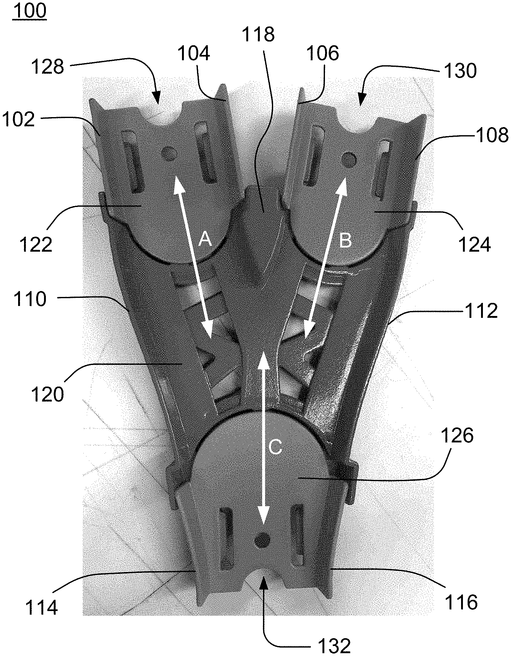
[0019] Referring now to FIG. 1, an exemplary embodiment of the toy vehicle track accessory is shown. The track accessory 100 is shown having three pathways that toy vehicles can travel along, specifically a first pathway A, second pathway B, and third pathway C. Depending on the orientation of the track accessory 100 when it is connected as part of a track set or raceway and the direction in which the toy vehicles travel through the track accessory 100 (as represented by the double arrows), the track accessory 100 facilitates the converging or diverging of toy vehicles traveling through the track accessory 100. In one instance, one or more toy vehicles enter the track accessory 100 via pathway A and/or pathway B. Pathway A and pathway B converge into pathway C, through which the toy vehicles exit the track accessory 100. In another instance, one or more toy vehicles enter the track accessory 100 via pathway C, which then bifurcates into pathway A and pathway B. The toy vehicles are randomly split between pathway A and pathway B as they exit the track accessory 100.
[0020] Though track accessory 100 is shown as having two pathways that converge into one pathway (or one pathway that bifurcates into two pathways), other embodiments of the track accessory may include any number of converging/diverging inlet and outlet pathways. For example, the track accessory may have three pathways that merge into one pathway or two pathways that split into four pathways. Furthermore, in the illustrative embodiment shown in FIG. 1, pathways A and B are each of a width that only allows for a single toy vehicle to travel along the pathway (i.e., single toy vehicle lane). In other embodiments, pathways A and/or B may have a width that allows for more than one toy vehicle lane such that multiple toy vehicles can travel along the same pathway concurrently.
[0021] The track accessory 100 has a planar track surface with vertical side walls that help retain toy vehicles within the pathways while toy vehicles travel through the track accessory 100. In FIG. 1, pathway A is lined in part by walls 102, 104, 110, pathway B is lined in part by walls 106, 108, 112, and pathway C is lined in part by walls 110, 112, 114, 116. The track accessory 100 also includes a divider 118 that protrudes from the track surface. Similar to the side walls 102-116, the divider 118 also helps retain toy vehicles within pathways A and B, as well as facilitates the converging or diverging of toy vehicles while the toy vehicles travel through the track accessory 100.
[0022] The track accessory 100 has a main body 120 with three pivotable track connectors 122, 124, 126 coupled to the main body 120. Each pivotable track connector 122, 124, 126 has a coupling portion 128, 130, 132. The coupling portion of the track connector may be any structure suitable for facilitating selective end-to-end connection or coupling of the track accessory 100 to another track segment or a component of a track set. For instance, the track connector may be configured to receive a tongue-and-groove friction-fit connector and/or a snap-together nesting tab. With the pivotable track connectors 122, 124, 126, the track accessory 100 can be coupled with other track segments in different orders and arrangements, which gives a child the freedom to creatively construct different raceway layouts.
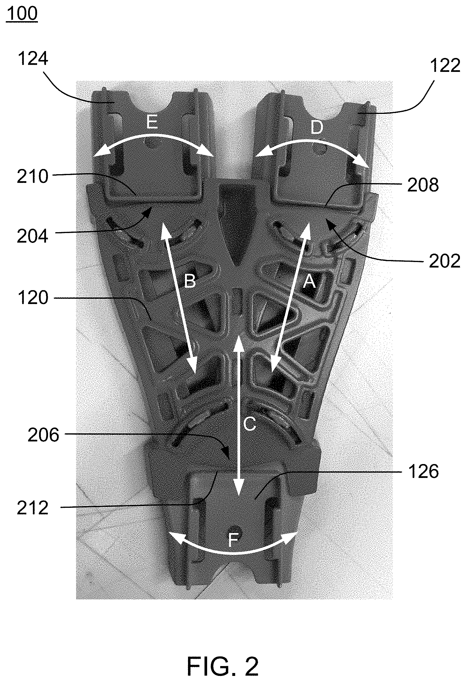
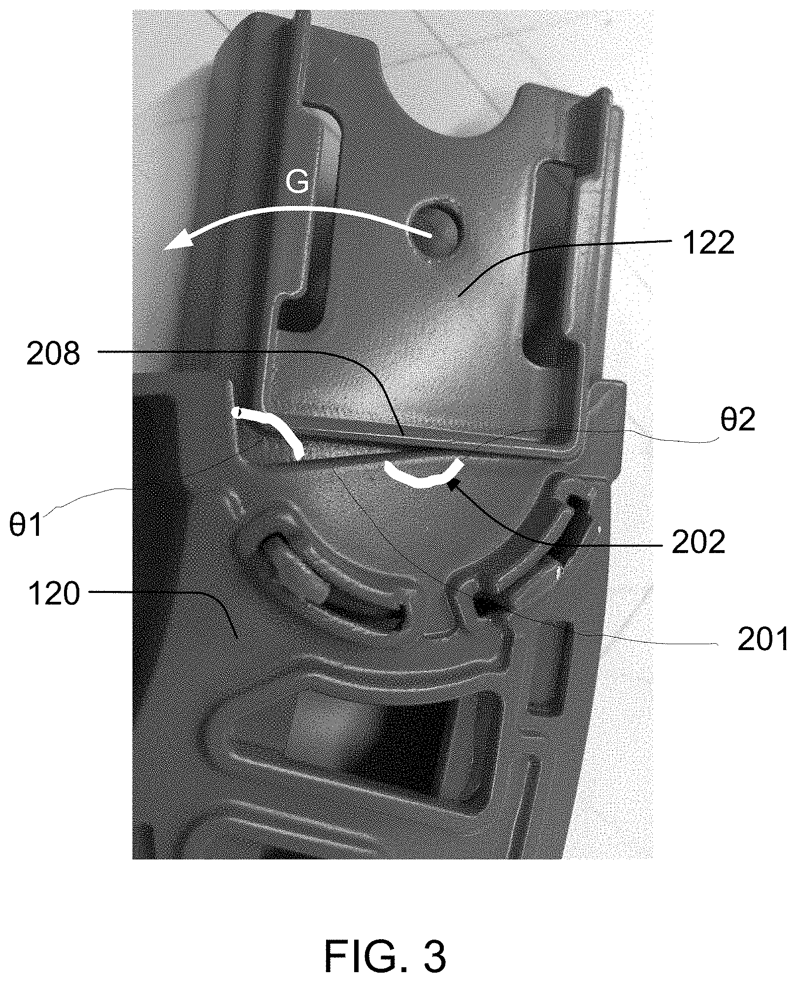
[0023] Referring now to FIG. 2 in combination with FIG. 3, the underside or bottom of pathways A, B, and C includes respective angular portions 202, 204, 206. Each angular portion 202, 204, 206 includes a convex edge 201 (see FIG. 3 for a representative edge) extending between two sidewalls to define corner angles .theta.1 (see FIG. 3 for a representative angle) at each edge of the angular portions 202, 204, 206. Approximately halfway between the two corners angles .theta.1, the interior side of the convex edge 201 defines an interior angle .theta.2 (see FIG. 3 for a representative angle) of less than 180 degrees. For instance, in the depicted embodiment, the angular portion 202 has an interior angle .theta.2 of approximately 160 degrees. Furthermore, the interior angles .theta.2 of the angular portions 202 and 204 may be the same and the interior angle .theta.2 of angular portion 206 may be different from the interior angle .theta.2 of angular portions 202, 204. For example, in the illustrative embodiment shown in FIG. 2, the interior angles .theta.2 of angular portions 202 and 204 are the same and the interior angle .theta.2 of the third angular portion 206 is different. In other embodiments, the interior angles .theta.2 of angular portions 202, 204, 206 are all the same. In yet other embodiments, the interior angles .theta.2 of angular portions 202, 204, 206 are all different.
[0024] Each track connector 122, 124, 126 includes a straight protrusion 208, 210, 212 that is configured to abut a respective angular portion 202, 204 or 206 when the track connector is pivoted to specific positions (see, e.g., FIGS. 3 and 4). The center of each of straight protrusions 208, 210, 212 is aligned proximate the vertex of its respective angular portion 202, 204, 206 prior to pivoting the track connectors 122, 124, 126, insofar as the vertex is the top or apex of the convex edge 201 defining the interior angle .theta.2. For example, a midpoint or center of the straight protrusions 208, 210, 212 may abut or be closely spaced (e.g., greater than 0 mm, but less than 20 mm) from a midpoint of the convex edge 201 of the angular portion 202, 204, 206 prior to pivoting the track connectors 122, 124, 126. Alternatively, a line bisecting the straight protrusions 208, 210, 212 at (i.e., extending perpendicularly from the midpoint or center) may align with a midpoint of the convex edge 201 of the angular portion 202, 204, 206 prior to pivoting the track connectors 122, 124, 126. Consequently, the angular portions 202, 204, 206 each restrict the range of movement of their respective track connector 122, 124, 126.
[0025] As an example, in FIG. 3, the track connector 122 has been pivoted such that a right half of the straight protrusion 208 abuts a right side of the angular portion 202 (insofar as "side" is used to described the portion of the angular portion between the vertex and the sidewall) and is prevented from being further pivoted towards the right. When the track connector 122 is pivoted to the left in direction G, the other half of the straight protrusion 208 eventually abuts the left side of the angular portion 202 and the track connector 122 is prevented from pivoting any further in direction G. Thus, an angular portion with a smaller interior angle .theta.2 allows the track connector to have a wider range of movement in comparison to an angular portion with a larger interior angle .theta.2.
[0026] The track connectors 122, 124, 126 are configured to pivot in directions that are coplanar with the main body 120. That is, each track connector 122, 124, 126 may rotate or pivot about an axis that is perpendicular to a travel direction of vehicles along the track accessory 100 and/or a support surface on which the track accessory 100 is resting. For example, in FIG. 2, track connectors 122, 124, 126 pivot respectively in directions D, E, F. The track connectors 122, 124, 126 may be individually pivoted and adjusted to different positions relative to the main body 120. FIG. 5 shows track connectors 122, 124, 126 all pivoted towards the left. Because the interior angle .theta.2 of the angular portion 206 underneath pathway C is smaller than the interior angles .theta.2 of the angular portions 202, 204 underneath pathways A and B, track connector 126 is able to pivot more (e.g., angularly further) than track connectors 122, 124. Overall, the track connectors 122, 124, 126 allow for greater variability in the positioning of track segments and accessories that are coupled to the track accessory 100. For example, in a raceway layout assembled using various conventional track segments and accessories, the ends of the track segments and accessories are often oriented in positions that prevent the ends from being aligned with and connected to certain track segments (e.g., preventing a closed loop from being formed). Since the track connectors 122, 124, 126 can pivot, the track accessory 100 can accommodate variances in the angles at which other track segments and accessories are able to connect with the track accessory 100. This allows the track accessory 100 to be easily combined with other track segments and accessories in a variety of raceway layouts.
[0027] As shown in FIG. 5, the track walls 110, 112 along the main body 120 include widened sections 302, 304, 306, 308 sized to accommodate portions of track walls 102, 108, 114, and 116. The divider 118 also has indented sections 310, 312 to accommodate portions of track walls 104, 106. The widened sections of track walls 110, 112 and the indented sections of the divider 118 allow the track connectors 122, 124, 126 to pivot while still helping retain toy vehicles within pathways A, B, and C while the toy vehicles travel through the track accessory 100.
[0028] In the illustrative embodiment shown in FIG. 5, the track connectors 122, 124, 126 each include a semicircular portion 314, 316, 318. The main body 120 includes semicircular indentations sized to receive the respective semicircular portions 314, 316, 318. The semicircular portions 314, 316, 318 allow the track connectors 122, 124, 126 to be pivoted to any position and still provide a substantially smooth planar surface as a toy vehicle travels from a track connector 122, 124, 126 to the main body 120 or vice versa.
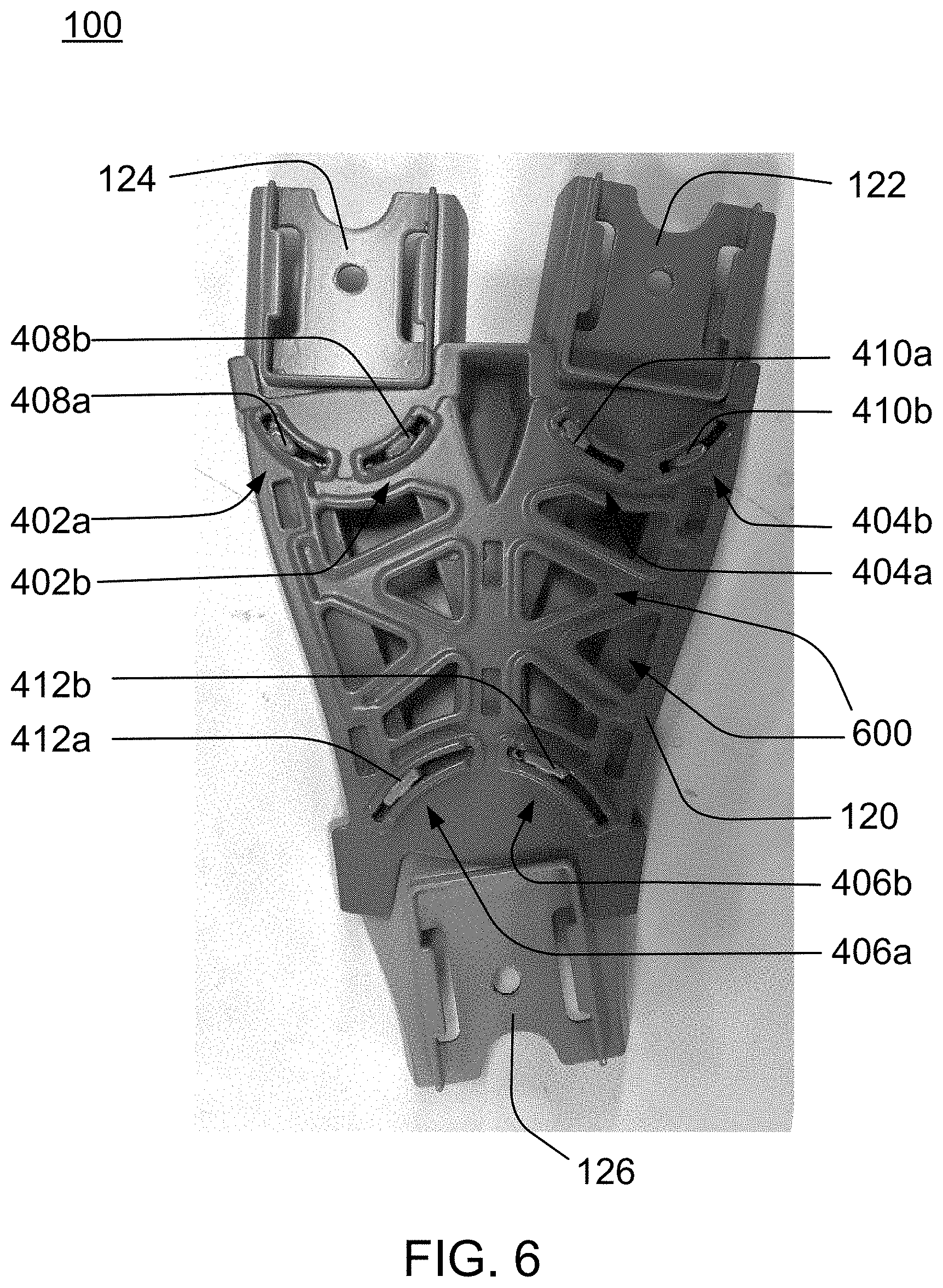
[0029] As shown in FIG. 6, in at least some embodiments, the track accessory 100 may include pairs of arcuate openings 402a, 402b, 404a, 404b, 406a, 406b along each pathway A, B, C on the main body 120. Track connectors 122, 124, 126 each have a pair of projections 408a, 408b, 410a, 410b, 412a, 412b positioned to engage with a respective pair of arcuate openings 402a, 402b, 404a, 404b, 406a, 406b. In this illustrative embodiment, the pair of projections are positioned on the underside of the semicircular portions 314, 316, 318, which further cover the arcuate openings on the main body 120. Each projection travels lengthwise along its respective arcuate opening while the track connector is pivoted. For instance, track connector 122 has a pair of projections 410a, 410b that engage with and travel along arcuate openings 404a, 404b.
[0030] In certain embodiments, for example as shown in FIG. 6, the main body 120 further comprises additional openings 600 that allow the track accessory 100 to have a lighter weight and require less material to produce/manufacture when compared to a track accessory without the additional openings 600. The openings 600 are specifically positioned to create a zig-zag pattern of material which allows the track accessory 100 to retain sufficient rigidity to support multiple toy vehicles traveling on the track accessory 100 at high speeds. Furthermore, wheel surfaces 602, 604, 606 on the upper or top side of the main body 120 partially cover portions of the openings 600 so that the wheels of the toy vehicles can smoothly roll across the openings.
[0031] Although the disclosed embodiments are illustrated and described herein as embodied in one or more specific examples, it is nevertheless not intended to be limited to the details shown, since various modifications and structural changes may be made therein without departing from the scope of the present embodiments and within the scope and range of equivalents of the claims.
[0032] Moreover, it is to be understood that terms such as "left," "right," "top," "bottom," "front," "rear," "side," "height," "length," "width," "upper," "lower," "interior," "exterior," "inner," "outer" and the like as may be used herein, merely describe points or portions of reference and do not limit the present embodiments to any particular orientation or configuration. Further, the term "exemplary" may be used herein to describe an example or illustration. Any embodiment described herein as exemplary is not to be construed as a preferred or advantageous embodiment, but rather as one example or illustration of a possible embodiment.
[0033] Finally, various features from one of the embodiments may be incorporated into another of the embodiments. Accordingly, it is appropriate that the appended claims be construed broadly and in a manner consistent with the scope of the disclosure as set forth in the following claims.
* * * * *
D00000
D00001
D00002
D00003
D00004
D00005
D00006
XML
uspto.report is an independent third-party trademark research tool that is not affiliated, endorsed, or sponsored by the United States Patent and Trademark Office (USPTO) or any other governmental organization. The information provided by uspto.report is based on publicly available data at the time of writing and is intended for informational purposes only.
While we strive to provide accurate and up-to-date information, we do not guarantee the accuracy, completeness, reliability, or suitability of the information displayed on this site. The use of this site is at your own risk. Any reliance you place on such information is therefore strictly at your own risk.
All official trademark data, including owner information, should be verified by visiting the official USPTO website at www.uspto.gov. This site is not intended to replace professional legal advice and should not be used as a substitute for consulting with a legal professional who is knowledgeable about trademark law.