Smoking Article
ENGLAND; William
U.S. patent application number 16/766433 was filed with the patent office on 2021-02-04 for smoking article. The applicant listed for this patent is NICOVENTURES TRADING LIMITED. Invention is credited to William ENGLAND.
| Application Number | 20210030060 16/766433 |
| Document ID | / |
| Family ID | 1000005163345 |
| Filed Date | 2021-02-04 |


| United States Patent Application | 20210030060 |
| Kind Code | A1 |
| ENGLAND; William | February 4, 2021 |
SMOKING ARTICLE
Abstract
Described herein is an aerosol generating article, the article including an aerosolizable material and a wrapping material arranged around the aerosolizable material, wherein the wrapping material includes a non-combustible material and the wrapping material extends from a first end of the aerosolizable material and over about 10% to about 85% of the distance to a second end of the aerosolizable material.
| Inventors: | ENGLAND; William; (London, GB) | ||||||||||
| Applicant: |
|
||||||||||
|---|---|---|---|---|---|---|---|---|---|---|---|
| Family ID: | 1000005163345 | ||||||||||
| Appl. No.: | 16/766433 | ||||||||||
| Filed: | November 15, 2018 | ||||||||||
| PCT Filed: | November 15, 2018 | ||||||||||
| PCT NO: | PCT/EP2018/081394 | ||||||||||
| 371 Date: | May 22, 2020 |
| Current U.S. Class: | 1/1 |
| Current CPC Class: | A24D 3/17 20200101; A24F 40/20 20200101; A24D 1/025 20130101; A24C 5/18 20130101; A24F 40/46 20200101 |
| International Class: | A24F 40/20 20060101 A24F040/20; A24D 1/02 20060101 A24D001/02 |
Foreign Application Data
| Date | Code | Application Number |
|---|---|---|
| Nov 24, 2017 | GB | 1719523.1 |
Claims
1. An aerosol generating article, comprising: an aerosolizable material; and a wrapping material arranged around the aerosolizable material, wherein the wrapping material comprises a non-combustible material and the wrapping material extends from a first end of the aerosolizable material and over about 10% to about 85% of a distance to a second end of the aerosolizable material.
2. The aerosol generating article according to claim 1, wherein the wrapping material circumscribes the aerosolizable material.
3. The aerosol generating article according to claim 1, wherein the aerosolizable material comprises tobacco.
4. The aerosol generating article according to claim 1, wherein the aerosolizable material is a rod of aerosolizable material.
5. The aerosol generating article according to claim 1, wherein the non-combustible material comprises a metal foil.
6. The aerosol generating article according to claim 5, wherein the metal foil comprises aluminum.
7. The aerosol generating article according to claim 1, wherein the wrapping material extends from the first end of the aerosolizable material and over about 20% to about 70% of the distance to the second end of the aerosolizable material.
8. The aerosol generating article according to claim 1, wherein the wrapping material extends from the first end of the aerosolizable material and over about 40% to about 65% of the distance to the second end of the aerosolizable material.
9. The aerosol generating article according to claim 1, wherein the wrapping material extends from the first end of the aerosolizable material and over about 50% to about 60% of the distance to the second end of the aerosolizable material.
10. The aerosol generating article according to claim 1, further comprising at least one of a filter or a cooling element.
11. The aerosol generating article according to claim 10, wherein the aerosol generating article comprises a filter and a cooling element, and wherein the cooling element is arranged between the aerosolizable material and the filter.
12. An aerosol generating assembly comprising the aerosol generating article according to claim 1.
13. The aerosol generating assembly according to claim 12, wherein the aerosol generating assembly is a tobacco heating product.
14. The aerosol generating assembly according to claim 12, wherein the aerosol generating assembly is a device into which the aerosol generating article is at least partially inserted in use.
15. A system comprising an aerosol generating device and the aerosol generating article according to claim 1.
16. A method for making an aerosol generating article comprising: wrapping an aerosolizable material in a wrapping material, wherein the wrapping material comprises a non-combustible material and the wrapping material extends from a first end of the aerosolizable material and over about 10% to about 85% of a distance to a second end of the aerosolizable material.
17. A method of preventing a user igniting or burning an aerosolizable material in an aerosol generating article, the method comprising: wrapping the aerosolizable material in a wrapping material, wherein the wrapping material comprises a non-combustible material and the wrapping material extends from a first end of the aerosolizable material and over about 10% to about 85% of a distance to a second end of the aerosolizable material.
Description
PRIORITY CLAIM
[0001] The present application is a National Phase entry of PCT Application No. PCT/EP2018/081394, filed Nov. 15, 2018, which claims priority from GB Patent Application No. 1719523.1, filed Nov. 24, 2017, each of which is hereby fully incorporated herein by reference.
TECHNICAL FIELD
[0002] The present disclosure relates to smoking articles and specifically, although not exclusively, to an aerosol generating article, the aerosol generating article comprising a wrapped aerosolizable material, and to an aerosol generating assembly containing an aerosol generating article, the aerosol generating article comprising a wrapped aerosolizable material.
BACKGROUND
[0003] Smoking articles such as cigarettes, cigars and the like burn tobacco during use to create tobacco smoke. Alternatives to these types of articles release compounds by heating without burning an aerosolizable material.
[0004] Apparatus is known that heats aerosolizable material to volatilize at least one component of the aerosolizable material, typically to form an aerosol which can be inhaled, without burning or combusting the aerosolizable material. Such apparatus is sometimes described as a "heat-not-burn" apparatus or a "tobacco heating product" (THP) or a "tobacco heating device" or similar. Various different arrangements for volatilizing at least one component of the aerosolizable material are known.
[0005] The material may be for example tobacco, other non-tobacco products or a combination, such as a blended mix, which may or may not contain nicotine.
SUMMARY
[0006] According to a first aspect, the disclosure provides an aerosol generating article, the aerosol generating article comprising an aerosolizable material and a wrapping material arranged around the aerosolizable material, and wherein the wrapping material comprises a non-combustible material and the wrapping material extends from a first end of the aerosolizable material and over about 10% to about 85% of the distance to a second end of the aerosolizable material.
[0007] In some cases, the wrapping material circumscribes the aerosolizable material.
[0008] In some cases, the aerosolizable material comprises tobacco.
[0009] In some cases, the aerosolizable material is a rod of aerosolizable material.
[0010] In some cases, the non-combustible material comprises a metal foil. For instance, the metal foil may comprise aluminum.
[0011] In some cases, the wrapping material extends from the first end of the aerosolizable material and over about 20% to about 70% of the distance to the second end of the aerosolizable material.
[0012] In some cases, the wrapping material extends from the first end of the aerosolizable material and over about 40% to about 65% of the distance to the second end of the aerosolizable material.
[0013] In some cases, the wrapping material extends from the first end of the aerosolizable material and over about 50% to about 60% of the distance to the second end of the aerosolizable material.
[0014] In some cases, the aerosol generating article may further comprise a filter and/or a cooling element. In some cases, the cooling element may be arranged between the aerosolizable material and the filter. In some cases, the filter may be arranged between the aerosolizable material and the cooling element.
[0015] According to a second aspect, the disclosure provides an aerosol generating assembly comprising a heater and an aerosol generating article according to the first aspect of the invention. In some cases, the aerosol generating assembly may be a tobacco heating product (also known as a heat not burn device).
[0016] A further aspect of the disclosure provides a system comprising an aerosol generating device and an aerosol generating article according to the first aspect.
[0017] A further aspect of the disclosure provides a process for making an aerosol generating article comprising wrapping an aerosolizable material in a wrapping material, wherein the wrapping material comprises a non-combustible material and the wrapping material extends from a first end of the aerosolizable material and over about 10% to about 85% of the distance to a second end of the aerosolizable material.
[0018] A further aspect of the disclosure provides a method of preventing a user igniting or burning an aerosolizable material in an aerosol generating article, the method comprising wrapping the aerosolizable material in a wrapping material, wherein the wrapping material comprises a non-combustible material and the wrapping material extends from a first end of the aerosolizable material and over about 10% to about 85% of the distance to a second end of the aerosolizable material.
[0019] To the extent that they are compatible, features of the invention described in the context of one aspect as explicitly disclosed in combination with each other aspect.
BRIEF DESCRIPTION OF THE FIGURES
[0020] Further features and advantages of the disclosure will become apparent from the following figures and description of examples of the invention (which are given by way of example only and do not place any limitation on the scope of the claims).
[0021] FIG. 1 is a schematic diagram of a side view of an aerosol generating article according to an example of the disclosure.
[0022] FIG. 2 is a schematic diagram of a first end view of an aerosol generating article according to an example of the disclosure.
[0023] FIG. 3 is a schematic diagram of a first end view of a different aerosol generating article according to an example of the disclosure.
[0024] FIG. 4 is a schematic diagram of a side view of an aerosol generating article according to an example of the disclosure.
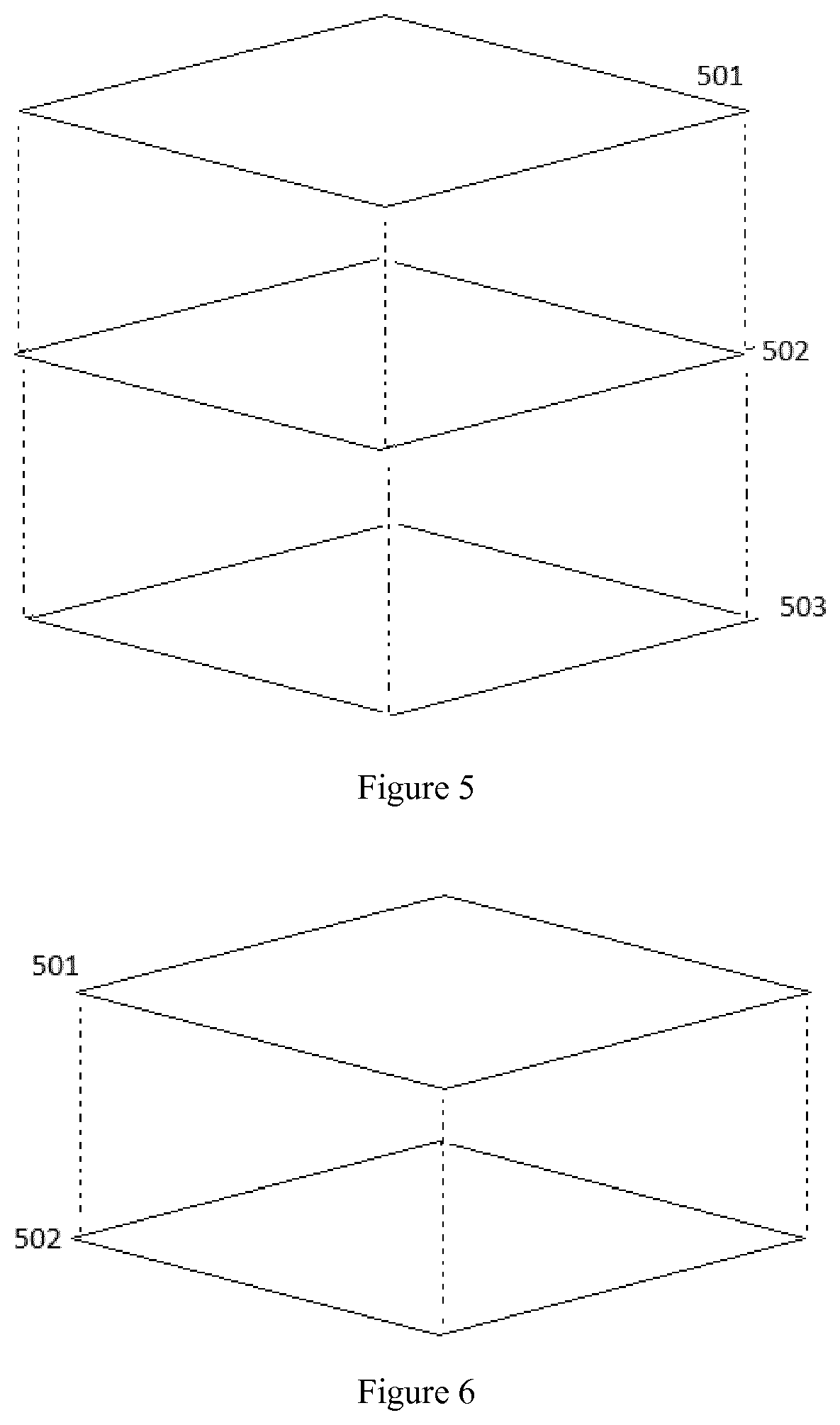
[0025] FIG. 5 is an exploded schematic diagram of a wrapping material that may be used in some examples.
[0026] FIG. 6 is an exploded schematic diagram of a wrapping material that may be used in some examples.
DETAILED DESCRIPTION
[0027] FIG. 1 is a schematic illustration of an example aerosol generating article. The aerosol generating article 101 includes an aerosolizable material 103 which is wrapped by a non-combustible material 102 from a first end of the aerosolizable material. In this example, the non-combustible material 102 extends over approximately 50% of the distance to the second end of the aerosolizable material.
[0028] In some cases, the wrapper may extend from the first end of the aerosolizable material over at least about 10%, 20%, 30%, 40% or 50% of the distance to the second end of the aerosolizable material.
[0029] A consideration when preparing an aerosol generating articles (such as tobacco heating products) is that they should not produce an acceptable smoking experience if the aerosolizable material is combusted, so that the user is not minded to burn the aerosolizable material. This is because the formulation of the aerosolizable material is not configured for combustion (and the aerosol that results from combustion may be less suitable for inhalation than the aerosol that results from heating but not burning that aerosolizable material, or than the aerosol which results from combustion of traditional cigarettes).
[0030] In use, the second end of the aerosolizable material is the mouth-end and the first end is the distal-end. (Accordingly, the second end may be alternatively referred to herein as the mouth-end, and the first end may alternatively be referred to herein as the distal-end.) Wrapping the distal-end of the aerosolizable material (i.e. the end that a user would attempt to ignite) in a non-combustible material prevents the aerosolizable material in the aerosol generating article from being burned and smoked as a conventional combustible cigarette. The inventors have established that the propensity to burn decreases as the proportion of aerosolizable material that is wrapped in a non-combustible material increases.
[0031] In some examples, the non-combustible wrapping material may be arranged around the circumference of the tobacco material. Optionally, the non-combustible wrapping material may also be arranged over the first end of the aerosolizable material, so that the first end is completely enclosed in the wrapping material. FIG. 2 illustrates an example in which the non-combustible material 102 is wrapped around the circumference of the aerosolizable material. The first end of the aerosol generating article 101 is not covered by the non-combustible material. FIG. 3 illustrates an alternative example of an aerosol generating article 101 in which the non-combustible material 102 completely encloses the first end of the aerosol generating article.
[0032] As used herein, the phrase "non-combustible" refers to a material that will not ignite or burn at temperatures normally associated with lighting (igniting) or burning of tobacco.
[0033] In some cases, the wrapper extends from the first end of the aerosolizable material over less than about 85%, 80%, 75%, 70%, 65% or 60% of the distance to the second end of the aerosolizable material.
[0034] Non-combustible materials may be more expensive than traditional tobacco wrapping materials such as paper. Therefore, it may be beneficial to use as little as possible, whilst balancing the need for a low propensity to burn.
[0035] Additionally, non-combustible materials are typically more difficult to use in manufacture than traditional tobacco wrapping materials, such as paper. For example, the inventors have established that non-combustible materials may be harder to cut than paper; this may influence the method of manufacture of the aerosolizable material, where (a) lengths of aerosolizable materials may be cut from a longer body, and (b) ventilation holes are provided in the wrapping material.
[0036] The inventors have established that wrapping 10-85% of the length of the aerosolizable material, the wrapper extending from the first end, satisfies these various competing requirements.
[0037] In some cases, the wrapping material may extend from the first end of the aerosolizable material and over about 20-70%, 40-65% or 50-60% of the distance to the second end of the aerosolizable material.
[0038] Examples of the aerosol generating article may additionally comprise further comprising a filter and/or a cooling element. In some cases, these additional components are circumscribed by a paper wrapper which also circumscribes the aerosolizable material. In such cases, a portion of the aerosolizable material is wrapped in a paper wrapper in addition to the wrapping material comprising a non-combustible material, and the paper wrapper may overlie or underlie the wrapping material comprising a non-combustible material.
[0039] For example, the second end (i.e. the mouth-end) of the aerosolizable material may be provided adjacent to a cooling element and/or a filter. A cooling element, if present, allows vapor components to condense to form an aerosol and/or spaces the very hot parts of the apparatus from the user. A filter, if present, may remove components from the fluid flow, affecting the chemical composition of the inhaled aerosol.
[0040] FIG. 4 illustrates an example of an aerosol generating article 101 which includes, in addition to the features of FIG. 1, a cooling element 104, a filter 105 and a mouth-end tube 106. The cooling element 104 and filter 105, as illustrated, may be arranged between the mouth-end of the aerosolizable material 103 and the mouth-end tube 106, so that flow from the aerosolizable material 103 passes through the cooling element 104 and filter 105 (or vice versa if the filter is arranged before the cooling element in the flow) before reaching the user. Although the example in FIG. 4 illustrates a cooling element 104, a filter 105 and a mouth-end tube 106, one or more of these elements may be omitted in other examples.
[0041] In some examples, the mouth-end tube, if present, 106 may be formed of for example paper, for example in the form of a spirally wound paper tube, cellulose acetate, cardboard, crimped paper, such as crimped heat resistant paper or crimped parchment paper, and/or polymeric materials, such as low density polyethylene (LDPE), or some other suitable material. The mouth-end tube 106 may be a hollow tube. Such a hollow tube may provide a filtering function to filter volatilized aerosolizable material. The mouth-end tube 106 may be elongate, in order to be spaced from the very hot part(s) of the main apparatus (not shown) that heats the aerosolizable material.
[0042] In some examples, the filter 105, if present, may be a filter plug, and may be made, for example, from cellulose acetate.
[0043] In some cases, the cooling element 104, if present, may comprise a monolithic rod having first and second ends and comprising plural through holes extending between the first and second ends. The through holes may extend substantially parallel to the central longitudinal axis of the rod. The through holes of the cooling element 104 may be arranged generally radially of the element when viewed in lateral cross-section. That is, in an example, the element has internal walls which define the through holes and which have two main configurations, namely radial walls and central walls. The radial walls extend along radii of the cross-section of the element and the central walls are centered on the center of the cross-section of the element. The central walls in one example are circular, though other regular or irregular cross-sectional shapes may be used. Likewise, the cross-section of the element in one example is circular, though other regular or irregular cross-sectional shapes may be used.
[0044] In an example, the majority of the through holes have a hexagonal or generally hexagonal cross-sectional shape. In this example, the element has what might be termed a "honeycomb" structure when viewed from one end.
[0045] In some cases, the cooling element 104 may comprise a hollow tube which spaces the filter 105, if present, from the very hot part(s) of the main apparatus that heats the aerosolizable material. The cooling element 104 may be formed of for example paper, for example in the form of a spirally wound paper tube, cellulose acetate, cardboard, crimped paper, such as crimped heat resistant paper or crimped parchment paper, and polymeric materials, such as low density polyethylene (LDPE), or some other suitable material.
[0046] The cooling element 104, if present, may be substantially incompressible. It may be formed of a ceramic material, or of a polymer, for example a thermoplastic polymer, which may be an extrudable plastics material. In an example, the porosity of the element is in the range 60% to 75%. The porosity in this sense may be a measure of the percentage of the lateral cross-sectional area of the element occupied by the through holes. In an example, the porosity of the element is around 69% to 70%.
[0047] Other examples of aerosol-cooling element are disclosed in PCT/GB2015/051253, the entirety of which is hereby expressly incorporated by reference, in particular in FIGS. 1 to 8 and the description from page 8, line 11 to page 18, line 16.
[0048] In further examples, the cooling element 104 may be formed from a sheet material that is folded, crimped or pleated to form through holes. The sheet material may be made, for example, from metal such as aluminum; polymeric plastics material such as polyethylene, polypropylene, polyethylene terephthalate, or polyvinyl chloride; or paper.
[0049] In some examples, the cooling element 104 and the filter 105 may be held together by a wrapper paper to form an assembly. The assembly may then be joined to the aerosolizable material by a further wrapper which circumscribes the assembly and at least the mouth end of the aerosolizable material to form the aerosol generating article 101. In other examples, the aerosol generating article 101 is formed by wrapping the cooling element 104, the filter 105 and the aerosolizable material 103 effectively in one operation, with no separate tipping paper being provided for the cooling element and/or filter components (if present).
[0050] In some cases, one or more ventilation apertures may be formed in the article. The ventilation apertures may provide airflow into the article during use which forms part of the inhaled aerosol. It may be desirable to reduce airflow over the distal-end of the aerosolizable material to reduce the propensity to burn, and so the apertures may be formed nearer to the mouth-end than to the distal-end. For example, the ventilation holes may be formed in the cooling element and/or filter, if present. Moreover, the ventilation holes may be formed in a part of the article that is not wrapped in the non-combustible material. The inventors have established that cutting the non-combustible material to form ventilation apertures may not be straightforward.
[0051] The aerosolizable material may be a rod of aerosolizable material. As used herein, the term "rod" generally refers to an elongate body which may be any suitable shape for use in an aerosol generating assembly. In some cases, the rod is substantially cylindrical.
[0052] In some cases, the aerosolizable material comprises tobacco. The tobacco may be any suitable solid tobacco, such as single grades or blends, cut rag or whole leaf, ground tobacco, tobacco fiber, cut tobacco, extruded tobacco, tobacco stem and/or reconstituted tobacco. The tobacco may be of any type including, without limitation, Virginia and/or Burley and/or Oriental tobacco.
[0053] In use, in some cases, the aerosol generating article may be arranged at least partially within a heating device to form an aerosol generating assembly which heats the article to generate an aerosol without burning. In some other cases, the article may be provided in an assembly with a fuel source, such as a combustible fuel source or chemical heat source, which heats but does not burn the aerosolizable material.
[0054] Wrapping Materials Comprising a Non-Combustible Material
[0055] In some cases, the non-combustible material comprises a metal foil. In some cases, it may consist essentially of or consist of a metal foil. Suitably, the metal foil may comprise, essentially consist of or consist of an aluminum foil. The metal foil is a non-combustible material that can nevertheless act to conduct heat to the aerosolizable material in use.
[0056] In some cases, the metal foil may be less than about 100 .mu.m, 50 .mu.m, 20 .mu.m, 10 .mu.m or 8 .mu.m thick. In some cases, it may be more than about 1 .mu.m, 3 .mu.m or 5 .mu.m thick.
[0057] In some cases, the aerosolizable material may be wrapped in more than one wrapping material. That is, in addition to the wrapping material comprising a non-aerosolizable material, the aerosolizable material may be wrapped in one or more further materials. These one or more further wrapping material(s) may cover more or less of the aerosolizable material than the wrapping material comprising a non-combustible material.
[0058] In some cases, the one or more further wrapping material(s) may circumscribe other components of the aerosol generating article (in addition to the wrapping material) as noted above.
[0059] In some cases, one or more further wrapping material(s) may comprise paper that may overlie and/or underlie the non-combustible wrapping material.
[0060] In some cases, the wrapping material that comprises a non-combustible material may be a laminate material. In some cases, the laminate material may comprise 2, 3, 4 or more layers.
[0061] Suitable laminate materials may comprise a paper layer and a metal foil layer (such as an aluminum foil layer). In some cases, the laminate material may consist of two layers, such as a paper layer and a metal foil layer.
[0062] As used herein, the term "laminate structure" refers to a multi-layer structure in which the layers are fastened together to form a single body. The layers may be fastened with an adhesive, for example. In other examples, the layers may be fastened by static interaction. In other examples, the laminate structure might be formed by (partially) melting a first layer, contacting the first layer with a second layer and allowing the first layer to solidify. Any suitable mechanism for fastening the layers together including, but not limited to, the above examples, tying, sewing, screwing, nailing, bolting, hooking, etc., may be employed to form the laminate structure.
[0063] In some cases, an adhesive may coat the surface of each layer. In other cases, an adhesive may be applied only to the periphery of the layers. In some cases, each layer in the laminate structure may be fastened to the adjacent layer(s). In some example laminate structures, the periphery of two layers may be fastened together with intermediate layers trapped in-between.
[0064] In some cases, the laminate wrapping material may comprise an inner layer comprising a metal foil and an outer layer comprising paper. FIG. 6 illustrates such an example. The laminate structure (indicated by dotted lines) an inner layer 502 and an outer layer 501. In some cases, the laminate wrapping material may consist of these two layers.
[0065] In some cases, the laminate wrapping material may comprise innermost and outermost layers that comprise paper, and an intermediate metal foil layer. FIG. 5 illustrates such an example. The laminate structure (indicated by dotted lines) includes the peripheral layers 501,503 and the intermediate layer 502. In some cases, the laminate wrapping material may consist of these three layers.
[0066] Wrapping the aerosolizable material in both a metal foil layer and a paper layer, suitably a laminate wrapper as described above, provides the desired non-combustibility. Additionally, the porosity of such wrapping is low, limiting the flow of side-stream air to the tobacco, further reducing the propensity to burn.
[0067] Moreover, the inventors have established that having an outer layer that comprises paper (and, in some cases, also having an innermost layer that comprises paper) may be beneficial because the laminate surface(s) then have a coefficient of friction of that paper. This means that the laminate wrapper can be more readily used in known cigarette manufacturing processes and machines. The laminate surfaces having a coefficient of friction equivalent to that of a cigarette paper allows the garniture belt of an aerosol generating article making machine to drive the laminate wrapper through the garniture during the aerosol generating article manufacturing process.
[0068] The inventors have further established that having paper in the innermost layer may be beneficial because it can act as a flavor carrier. That is, in some cases, the innermost layer of the laminate wrapping material comprises paper and a flavorant which is transferred to the aerosolizable material when wrapped around the aerosolizable material and heated. In some cases, the flavorant is impregnated into the paper in the innermost layer. In some cases, the flavorant may comprise menthol.
[0069] Paper in the laminate wrapping materials described herein may have a basis weight of at least about 10 gm.sup.-2, 15 gm.sup.-2, 20 gm.sup.-2 or 25 gm.sup.-2 to about 50 gm.sup.-2, 45 gm.sup.-2, 40 gm.sup.-2 or 35 gm.sup.-2. Paper having a density in this range has a low porosity, which further reduces the propensity to burn through limiting the oxygen levels at the aerosolizable material.
[0070] The paper may be treated with one or more burn-retardant substances.
[0071] The laminate material can be wound onto a bobbin core for use with standard cigarette makers that are fed from a single paper bobbin.
[0072] The laminate material may be formed using any suitable lamination technique. In one example, the layers may be adhered together.
[0073] The above examples are to be understood as illustrative examples of the invention. It is to be understood that any feature described in relation to any one example may be used alone, or in combination with other features described, and may also be used in combination with one or more features of any other of the examples, or any combination of any other of the examples. Furthermore, equivalents and modifications not described above may also be employed without departing from the scope of the invention, which is defined in the accompanying claims.
* * * * *
D00000
D00001
D00002
XML
uspto.report is an independent third-party trademark research tool that is not affiliated, endorsed, or sponsored by the United States Patent and Trademark Office (USPTO) or any other governmental organization. The information provided by uspto.report is based on publicly available data at the time of writing and is intended for informational purposes only.
While we strive to provide accurate and up-to-date information, we do not guarantee the accuracy, completeness, reliability, or suitability of the information displayed on this site. The use of this site is at your own risk. Any reliance you place on such information is therefore strictly at your own risk.
All official trademark data, including owner information, should be verified by visiting the official USPTO website at www.uspto.gov. This site is not intended to replace professional legal advice and should not be used as a substitute for consulting with a legal professional who is knowledgeable about trademark law.