Directional Garlic Seed Throwing Mechanism And Control Method Of The Same
SHEN; JINGXIN ; et al.
U.S. patent application number 16/629034 was filed with the patent office on 2021-02-04 for directional garlic seed throwing mechanism and control method of the same. This patent application is currently assigned to SHANDONG ACADEMY AGRICULTURAL MACHINERY SCIENCES. The applicant listed for this patent is SHANDONG ACADEMY AGRICULTURAL MACHINERY SCIENCES, Shandong University. Invention is credited to GANG CHEN, Xian Ying FENG, QING LONG LI, JINGXIN SHEN, YITIAN SUN, YONGJIA SUN, Peng Yan, Jun Zhou.
| Application Number | 20210029868 16/629034 |
| Document ID | / |
| Family ID | 1000005198537 |
| Filed Date | 2021-02-04 |


| United States Patent Application | 20210029868 |
| Kind Code | A1 |
| SHEN; JINGXIN ; et al. | February 4, 2021 |
DIRECTIONAL GARLIC SEED THROWING MECHANISM AND CONTROL METHOD OF THE SAME
Abstract
A directional garlic seed throwing mechanism includes a base, a rotating device, a vision sensor, a seed throwing guide plate, a seed guide pipe and a plurality of bulbil adjusting devices. The rotating device includes a rotating motor detachably connected to the base and a turntable connected to an output end of the rotating motor. The seed throwing guide plate is arranged on the turntable to enable garlic seeds of seed containing bowls to fall into the seed guide pipe. The seed guide pipe has an upper port right below the bulbil adjusting devices and arranged on the base. An even number of the bulbil adjusting devices are fixed on the turntable uniformly and symmetrically and include the seed containing bowls and bulbil direction control devices for driving the bowls to rotate 180 degrees.
| Inventors: | SHEN; JINGXIN; (Shandong, CN) ; SUN; YITIAN; (Shandong, CN) ; SUN; YONGJIA; (Shandong, CN) ; CHEN; GANG; (Shandong, CN) ; LI; QING LONG; (Shandong, CN) ; FENG; Xian Ying; (Shandong, CN) ; Zhou; Jun; (Shandong, CN) ; Yan; Peng; (Shandong, CN) | ||||||||||
| Applicant: |
|
||||||||||
|---|---|---|---|---|---|---|---|---|---|---|---|
| Assignee: | SHANDONG ACADEMY AGRICULTURAL
MACHINERY SCIENCES Shandong CN Shandong University Shandong CN |
||||||||||
| Family ID: | 1000005198537 | ||||||||||
| Appl. No.: | 16/629034 | ||||||||||
| Filed: | September 19, 2018 | ||||||||||
| PCT Filed: | September 19, 2018 | ||||||||||
| PCT NO: | PCT/CN2018/106372 | ||||||||||
| 371 Date: | January 7, 2020 |
| Current U.S. Class: | 1/1 |
| Current CPC Class: | A01C 7/206 20130101; A01C 7/10 20130101 |
| International Class: | A01C 7/10 20060101 A01C007/10; A01C 7/20 20060101 A01C007/20 |
Foreign Application Data
| Date | Code | Application Number |
|---|---|---|
| Aug 22, 2018 | CN | 201810958748.0 |
Claims
1. A directional garlic seed throwing mechanism, comprising: a base, a rotating device, a vision sensor, a seed throwing guide plate, a seed guide pipe and a plurality of bulbil adjusting devices, wherein the rotating device comprises a rotating motor and a turntable; the rotating motor is detachably connected to the base; an output end of the rotating motor is connected with the turntable; an even number of the bulbil adjusting devices are provided and fixedly mounted on the turntable uniformly and symmetrically; the bulbil adjusting devices comprise seed containing bowls and bulbil direction control devices used for driving the seed containing bowls to rotate 180 degrees; an upper port of the seed guide pipe is located right below the bulbil adjusting devices and arranged on the base; and the seed throwing guide plate is arranged on the turntable, such that garlic seeds in the seed containing bowls fall into the seed guide pipe.
2. The directional garlic seed throwing mechanism according to claim 1, wherein the bulbil direction control device comprises a cam device and a rotary guide device; the cam device comprises a cam, a sliding rod and a roller; a driving end of the sliding rod is provided with the roller and abuts against a curved surface of the cam; a resetting device for driving the roller on the sliding rod to abut against the cam is arranged on a mounting seat; the rotary guide device is arranged on the mounting seat and moves along a curve of a surface of the sliding rod to drive the sliding rod to rotate; a seed containing device is arranged above the resetting device and connected with the sliding rod; each of the bulbil adjusting devices further comprises an electromagnet for enabling operation of the cam device; the electromagnet is detachably connected below a support which is fixedly connected to the base; and a reinforcing plate is arranged between the support and the base.
3. The directional garlic seed throwing mechanism according to claim 2, wherein the rotary guide device comprises a fixed seat, a vertical rod and a cantilever shaft; the fixed seat is detachably connected with the base; two ends of the vertical rod are respectively connected with the fixed seat and the cantilever shaft; a bearing is mounted at a tail end of the cantilever shaft, and is matched with a guide groove on a surface of the sliding rod.
4. The directional garlic seed throwing mechanism according to claim 2, wherein the resetting device comprises a pressure spring, a linear bearing and a flange plate; the linear bearing is connected with a fixed seat of the rotary guide device, and is in sliding connection with the sliding rod; the flange plate is arranged at an upper end of the sliding rod and connected with a bottom portion of the seed containing device; the pressure spring passes through the sliding rod; and one end of the pressure spring is in contact with the flange plate, and the other end of the pressure spring is in contact with the linear bearing.
5. The directional garlic seed throwing mechanism according to claim 1, wherein the seed throwing guide plate is welded and connected with the base, and a longitudinal central surface of the seed throwing guide plate passes through a center of circle of the turntable.
6. The directional garlic seed throwing mechanism according to claim 2, further comprising a controller, wherein the controller is respectively connected with a touch display screen, the vision sensor, the electromagnets, the rotating motor and a speed sensor.
7. A control method of the directional garlic seed throwing mechanism according to claim 6, comprising following steps: (1) inputting a seed spacing of garlic sowing through a touch display screen; (2) pressing a confirm button to display a working interface by the touch display screen; (3) reading, by the controller, a speed of the speed sensor, and simultaneously calculating a rotating speed and an action time interval of the rotating motor according to the set seed spacing; (4) when the bulbil adjusting devices for receiving garlic seeds rotate to a position below a vision sensor, acquiring, by the vision sensor, garlic seed image information; (5) analyzing, by the controller, the garlic seed image information, and determining a garlic bulbil direction; (6) driving, by the rotating motor, the bulbil adjusting devices to rotate; (7) when the garlic bulbil direction is consistent with a desired direction, the electromagnets does not work, and when the garlic bulbil direction is opposite to the desired direction, controlling, by the controller, the electromagnets to operate such that the bulbil adjusting devices rotate 180 degrees to complete adjustment of the bulbil direction; and (8) driving, by the rotating motor, the bulbil adjusting devices to rotate to a seed throwing position, and driving the seed containing bowls to tilt under an action of the seed throwing guide plate to enable the garlic seeds to slide into the seed guide pipe under an action of the gravity and then slide into a duck-billed indenting tool by keeping the bulbil direction upward under restriction of the seed guide pipe, and completing directional seed throwing.
Description
BACKGROUND
Technical Field
[0001] The present disclosure relates to a part of a garlic seeder, in particular to a directional garlic seed throwing mechanism and a control method of the same, and belongs to the technical field of agricultural machinery.
Description of Related Art
[0002] According to the agronomic requirements of garlic sowing, bulbils need to be upwards planted during garlic sowing. An existing garlic sowing technology in China does not fully solve the problem that how to control roots of the bulbils to be downward in a garlic planting process and the bulbils to be upright after seed throwing, resulting in the fact that the garlic sowing can only be manually done for a long time and then causing problems of high labor intensity, low production efficiency, time waste, labor waste, high production cost and the like; and as a result, the mechanical production of the garlic sowing is severely restricted.
SUMMARY
[0003] In order to overcome the above shortcomings in the prior art, the present disclosure provides a directional garlic seed throwing mechanism and a control method thereof, and designs results and technical parameters of the directional garlic seed throwing mechanism, so that directional seed throwing with garlic bulbils oriented upwards may be realized, and a foundation is laid for replacing manual garlic sowing with mechanical operation.
[0004] The present disclosure is realized by the following technical solution.
[0005] A directional garlic seed throwing mechanism includes a base, a rotating device, a vision sensor, a seed throwing guide plate, a seed guide pipe and a plurality of bulbil adjusting devices. The rotating device includes a rotating motor and a turntable. The rotating motor is detachably connected to the base. An output end of the rotating motor is connected with the turntable. An even number of the bulbil adjusting devices are provided and fixedly mounted on the turntable uniformly and symmetrically. The bulbil adjusting devices include seed containing bowls and bulbil direction control devices used for driving the seed containing bowls to rotate 180 degrees. An upper port of the seed guide pipe is located right below the bulbil adjusting devices and arranged on the base. The seed throwing guide plate is arranged on the turntable, such that garlic seeds of the seed containing bowls fall into the seed guide pipe.
[0006] According to the preferred solution of the directional garlic seed throwing mechanism, the bulbil direction control device includes a cam device and a rotary guide device. The cam device includes a cam, a sliding rod and a roller. A driving end of the sliding rod is provided with the roller and abuts against a curved surface of the cam. A resetting device for driving the roller on the sliding rod to abut against the cam is arranged on a mounting seat. The rotary guide device is arranged on the mounting seat and moves along a curve of a surface of the sliding rod to drive the sliding rod to rotate. A seed containing device is arranged above the resetting device and connected with the sliding rod. Each of the bulbil adjusting devices further includes an electromagnet for enabling operation of the cam device. The electromagnet is detachably connected below a support which is fixedly connected to the base. A reinforcing plate is arranged between the support and the base.
[0007] According to the preferred solution of the directional garlic seed throwing mechanism, the rotary guide device includes a fixed seat, a vertical rod and a cantilever shaft. The fixed seat is detachably connected with the base. Two ends of the vertical rod are respectively connected with the fixed seat and the cantilever shaft. A bearing is mounted at a tail end of the cantilever shaft, and is matched with a guide groove on a surface of the sliding rod.
[0008] According to the preferred solution of the directional garlic seed throwing mechanism, the resetting device includes a pressure spring, a linear bearing and a flange plate. The linear bearing is connected with the fixed seat, and is in sliding connection with the sliding rod. The flange plate is arranged at an upper end of the sliding rod and connected with a bottom portion of the seed containing device. The pressure spring passes through the sliding rod. One end of the pressure spring is in contact with the flange plate, and the other end of the pressure spring is in contact with the linear bearing.
[0009] According to the preferred solution of the directional garlic seed throwing mechanism, the seed throwing guide plate is welded and connected with the base, and a longitudinal central surface of the seed throwing guide plate passes through a center of circle of the turntable.
[0010] According to the preferred solution of the directional garlic seed throwing mechanism, the mechanism further includes a controller. The controller is respectively connected with a touch display screen, the vision sensor, the electromagnets, the turntable motor and a speed sensor.
[0011] A control method of the directional garlic seed throwing mechanism includes following steps.
[0012] (1) Inputting a seed spacing of garlic sowing through a touch display screen.
[0013] (2) Pressing a confirm button to display a working interface by the touch display screen.
[0014] (3) Reading, by the controller, a speed of the speed sensor, and simultaneously calculating a rotating speed and an action time interval of the turntable motor according to the set seed spacing.
[0015] (4) In a rotating process of the turntable motor, detecting, by a position sensor, a position of a bulbil adjusting mechanism, wherein when the bulbil adjusting mechanism is detected, the turntable motor stops working, and at this moment, the bulbil adjusting devices for receiving garlic seeds rotate below a vision sensor, and the vision sensor acquires garlic seed image information.
[0016] (5) Analyzing, by the controller, the garlic seed image information, and determining a garlic bulbil direction.
[0017] (6) Driving, by the turntable motor, the bulbil adjusting devices to rotate.
[0018] (7) When the garlic bulbil direction is consistent with a desired direction, electromagnets does not work, and when the garlic bulbil direction is opposite to the desired direction, controlling, by the controller, the electromagnets to operate such that the bulbil adjusting devices rotate 180 degrees to complete adjustment of the bulbil direction.
[0019] (8) Driving, by the turntable motor, the bulbil adjusting devices to rotate to a seed throwing position, and driving the seed containing bowls to tilt under an action of the seed throwing guide plate to enable the garlic seeds to slide into the seed guide pipe under an action of the gravity and then slide into a duck-billed indenting tool by keeping the bulbil direction upward under restriction of the seed guide pipe, and completing directional seed throwing.
[0020] The working principle of the present disclosure is as follows.
[0021] The directional garlic seed throwing mechanism realizes detection through a plurality of sensors, and adjusts the sequential matching work of each component through the controller to realize directional garlic seed throwing. The visual sensor acquires the garlic bulbil image information, and the controller analyzes and judges the garlic bulb image information. If the garlic bulbil direction is consistent with the desired direction, the garlic bulbil direction is not adjusted. If the garlic bulbil direction is inconsistent with the desired direction, the electromagnets act to adjust the garlic bulbil direction, and then directional seed throwing is completed under the guidance of the guide plate.
[0022] The present disclosure has the advantages below.
[0023] 1. The garlic bulbil direction control device may adjust the garlic bulbil direction as required, and the seed throwing guide plate enables the garlic seeds of the seed containing bowls to fall into the seed guide pipe; therefore, without complicated power mechanism, the directional garlic seed throwing mechanism is simple in structure, high in practicability, convenient and reliable to use, applicable to garlic sowing machinery, capable of remarkably improving the accuracy of controlling bulbils upwards during mechanical garlic sowing and capable of improving the operation quality of the garlic sowing machinery.
[0024] 2. The controller analyzes and processes the garlic seed image information acquired by the vision sensor, so that the garlic bulbil direction may be accurately distinguished, and the recognition is accurate and reliable. The vision sensor acquires the garlic seed image information, and may analyze the image to determine operation conditions such as lack of seeds and re-sowing to improve the sowing quality. The controller analyzes the garlic seed image, counts the garlic seeds, monitors a sowing process, and provides a reliable scientific basis for monitoring and analyzing the operation quality. The controller coordinates and drives the various components and adjusts the consistency of the garlic bulbil directions to realize sowing work with consistent garlic bulbil directions and improve the operation quality of the mechanical garlic sowing. The touch display screen displays operation parameters such as a current operation speed, a working area and the quantity of seeds, and parameters such as the seed spacing are set through the touch display screen, thus realizing human-machine interaction and improving the operation quality and the intelligence level of the whole mechanism.
BRIEF DESCRIPTION OF THE DRAWINGS
[0025] The accompanying drawings provide further understandings of the present disclosure, and constitute one part of the description. The drawings are used for interpreting the present disclosure together with the embodiments of the present disclosure, not for limiting the present disclosure.
[0026] FIG. 1 is a front view of the present disclosure;
[0027] FIG. 2 is a left view of the present disclosure;
[0028] FIG. 3 is a top view of the present disclosure;
[0029] FIG. 4 is a schematic structural diagram of a control system of the present disclosure;
[0030] FIG. 5 is a schematic structural diagram of a bulbil adjusting device;
[0031] FIG. 6 is a schematic structural diagram of a rotary guide device; and
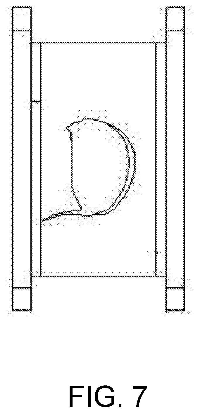
[0032] FIG. 7 is a schematic top view of a seed containing bowl.
[0033] In the drawings, 1: vision sensor; 2: bulbil adjusting mechanism II; 3: turntable; 4: baffle plate; 5: seed guide pipe; 6: base; 7: electromagnet; 8: support; 9: reinforcing plate; 10: turntable motor; 11: seed throwing guide plate; 12: touch display screen; 13: controller; 14: speed sensor; 15: bulbil adjusting mechanism III; 16: bulbil adjusting mechanism V; 17: bulbil adjusting mechanism I; 18: position detection sensor support; 19: position sensor; 2-1: flange plate; 2-2: fixed seat; 2-3: guide groove; 2-4: cam; 2-6: pressure spring; 2-7: linear bearing; 2-9: sliding rod; 2-10: roller; 2-12: vertical rod; and 2-13: cantilever shaft.
DESCRIPTION OF THE EMBODIMENTS
[0034] The preferred embodiments of the present disclosure will be explained in details below with reference to the accompanying drawings. It should be understood that the preferred embodiments described herein are merely to illustrate and explain the present disclosure, not to limit the present disclosure.
[0035] Referring to FIG. 1, FIG. 2 and FIG. 3, a directional garlic seed throwing mechanism includes a base 6, a rotating device, a vision sensor 1, a seed throwing guide plate 11, a seed guide pipe 5 and a plurality of bulbil adjusting devices. The rotating device includes a rotating motor 10 and a turntable 3. The rotating motor 10 is detachably connected to the base 6. An output end of the rotating motor 10 is connected with the turntable 3. There are four bulbil adjusting devices, which are respectively a bulbil adjusting mechanism I 17, a bulbil adjusting mechanism II 2, a bulbil adjusting mechanism III 15 and a bulbil adjusting mechanism V 16 and fixedly mounted on the turntable 3 uniformly and symmetrically. The bulbil adjusting devices include seed containing bowls and bulbil direction control devices used for driving the seed containing bowls to rotate 180 degrees. An upper port of the seed guide pipe 5 is located right below the bulbil adjusting devices and arranged on the base 6. The seed throwing guide plate 11 is arranged on the turntable 3, so that garlic seeds in the seed containing bowls fall into the seed guide pipe 5.
[0036] Referring to FIG. 5 and FIG. 6, the bulbil direction control device includes a cam device and a rotary guide device. The cam device includes a cam 2-4, a sliding rod 2-9 and a roller 2-10. A driving end of the sliding rod 2-9 is provided with the roller 2-10 and abuts against a curved surface of the cam 2-4. A resetting device for driving the roller 2-10 on the sliding rod 2-9 to abut against the cam 2-4 is arranged on a mounting seat 1. The rotary guide device is arranged on the mounting seat 1 and moves along a curve of a surface of the sliding rod 2-9 to drive the sliding rod 2-9 to rotate. A seed containing device is arranged above the resetting device and connected with the sliding rod 2-9. The bulbil adjusting device further includes an electromagnet 7 for enabling operation of the cam device. The electromagnet 7 is detachably connected below a support 8 which is fixedly connected to the base 6. A reinforcing plate 9 is arranged between the support 8 and the base 6. The rotary guide device includes a fixed seat 2-2, a vertical rod 2-12 and a cantilever shaft 2-13. The fixed seat 2-2 is detachably connected with the base 1. Two ends of the vertical rod 2-12 are respectively connected with the fixed seat 2-2 and the cantilever shaft 2-13. A bearing 2-14 is mounted at a tail end of the cantilever shaft 2-13, and is matched with a guide groove 2-3 on the surface of the sliding rod 2-9. The resetting device includes a pressure spring 2-6, a linear bearing 2-7 and a flange plate 2-1. The linear bearing 2-7 is connected with the fixed seat 2-2, and is in sliding connection with the sliding rod 2-9. The flange plate 2-1 is arranged at an upper end of the sliding rod 2-9 and connected with a bottom portion of the seed containing device 4. The pressure spring 6 passes through the sliding rod 2-9. One end of the pressure spring 6 is in contact with the flange plate 2-1, and the other end of the pressure spring 6 is in contact with the linear bearing 2-7.
[0037] In the present embodiment, the seed throwing guide plate 11 is welded and connected with the base 6, and a longitudinal central surface of the seed throwing guide plate 11 passes through the circle center of the turntable 3.
[0038] Referring to FIG. 1, FIG. 2 and FIG. 7, each of the seed containing bowls includes a front surface, a back surface and a bottom surface. The front surface and the back surface are planar surfaces, and the bottom surface is of an arc-shaped structure having openings in left and right sides. The left and right sides of the seed containing bowl are rotatably connected with baffle plates 4 through baffle plate pin shafts. A torsional spring is arranged below the seed containing bowl.
[0039] Referring to FIG. 4, the present embodiment further includes a controller 13. The controller 13 is respectively connected with a touch display screen 12, the vision sensor 1, the electromagnets 7, the turntable motor 10 and a speed sensor 14. The touch display screen 12 may set a seed spacing of garlic sowing and display information such as an operation speed, an operation area and the quantity of seeds, and is convenient for an operator to monitor the operation process and quality. The speed sensor 14 detects an operation speed. The controller 13 receives speed information and a seed spacing signal and automatically calculates and controls a rotating speed and an action time interval of the turntable motor 10, so as to guarantee the seed spacing consistency under different operation speeds. The controller 13 uses a DSP (Digital Signal Processing) chip as a control unit for calculation and processing. A serial port 232 of the touch display screen 12 is connected with the controller. The vision sensor 14 is a CMOS (Complementary Metal-Oxide-Semiconductor Transistor) image sensor to supplement how to connect the turntable motor 10 with the controller 13.
[0040] The controller 13 drives the turntable motor 10 to rotate through a PWM (Pulse Width Modulation) signal.
[0041] A control method of a directional garlic seed throwing mechanism includes following steps.
[0042] (1) A seed spacing of garlic sowing is input through a touch display screen 12.
[0043] (2) A confirm button is pressed to display a working interface by the touch display screen 12;
[0044] (3) The controller 13 reads a speed of the speed sensor 14, and simultaneously calculates a rotating speed and an action time interval of the turntable motor 10 according to the set seed spacing.
[0045] (4) In a rotating process of the turntable motor, a position sensor 19 detects a position of a bulbil adjusting mechanism 16, wherein when the bulbil adjusting mechanism 16 is detected, the turntable motor 10 stops working, and at this moment, the bulbil adjusting devices for receiving garlic seeds rotate below a vision sensor 14, and the vision sensor 14 acquires garlic seed image information.
[0046] (5) The controller 13 analyzes the garlic seed image information, and determines a garlic bulbil direction.
[0047] (6) The turntable motor 10 drives the bulbil adjusting devices to rotate.
[0048] (7) When the garlic bulbil direction is consistent with a desired direction, electromagnets does not work, and when the garlic bulbil direction is opposite to the desired direction, the controller controls the electromagnets 7 to operate such that the bulbil adjusting devices rotate 180 degrees to complete adjustment of the bulbil direction.
[0049] (8) The turntable motor 10 drives the bulbil adjusting devices to rotate to a seed throwing position, and drives the seed containing bowls to tilt under an action of a seed throwing guide plate to enable the garlic seeds to slide into the seed guide pipe 5 under an action of the gravity and then slide into a duck-billed indenting tool by keeping the bulbil direction upward under the restriction of the seed guide pipe 5, thereby completing directional seed throwing.
[0050] During the operation, the directional garlic seed throwing mechanism is mounted below a seed taking mechanism, and the garlic seeds taken out by the seed taking mechanism fall into a bulbil adjusting mechanism I 17. The turntable motor 10 drives the turntable to rotate 45 degrees. The vision sensor 1 acquires image information of the garlic seeds in the bulbil adjusting mechanism I 17, and uploads the image information to the controller 13. Meanwhile, the turntable motor 10 rotates 90 degrees to drive the bulbil adjusting mechanism I 17 to rotate to a position of a bulbil adjusting mechanism III 15. When the bulbil direction needs to be adjusted, the electromagnets 7 act to enable the bulbil adjusting mechanism I 17 to rotate 180 degrees to realize adjustment of the garlic bulbil direction. The turntable motor 10 rotates 90 degrees to drive the bulbil adjusting mechanism I 17 to rotate to a position of a bulbil adjusting mechanism V 16. Under the action of the guide plate 11, an upper part of the bulbil adjusting mechanism I 17 tilts, and the baffle plate 4 is opened to enable garlic bulbils to fall into the seed guide pipe 5 in an upward direction to complete directional seed throwing. In this process, the position sensor 19 detects the position of the bulbil adjusting mechanism 16. When the bulbil adjusting mechanism 16 is detected, the turntable motor 10 stops the action.
[0051] Finally, it should be noted that the above is only preferred embodiments of the present disclosure, and is not intended to limit the present disclosure. Although the present disclosure has been described in detail with reference to the foregoing embodiments, those skilled in the art can still modify the technical solutions disclosed in all the foregoing embodiments, or make equivalent substitutions to partial technical features thereof. Any modifications, equivalent substitutions, improvements and the like that are made without departing from the spirit and principle of the present disclosure shall all fall within the protection scope of the present disclosure.
* * * * *
D00000
D00001
D00002
D00003
D00004
XML
uspto.report is an independent third-party trademark research tool that is not affiliated, endorsed, or sponsored by the United States Patent and Trademark Office (USPTO) or any other governmental organization. The information provided by uspto.report is based on publicly available data at the time of writing and is intended for informational purposes only.
While we strive to provide accurate and up-to-date information, we do not guarantee the accuracy, completeness, reliability, or suitability of the information displayed on this site. The use of this site is at your own risk. Any reliance you place on such information is therefore strictly at your own risk.
All official trademark data, including owner information, should be verified by visiting the official USPTO website at www.uspto.gov. This site is not intended to replace professional legal advice and should not be used as a substitute for consulting with a legal professional who is knowledgeable about trademark law.