Charged Particle Beam Device
MOTOMURA; Shunichi ; et al.
U.S. patent application number 17/040121 was filed with the patent office on 2021-01-28 for charged particle beam device. The applicant listed for this patent is Hitachi High-Tech Corporation, Japan Fine Ceramics Center. Invention is credited to Takeharu KATO, Tadahiro KAWASAKI, Shunichi MOTOMURA, Tsunenori NOMAGUCHI, Ryuji YOSHIDA.
| Application Number | 20210027977 17/040121 |
| Document ID | / |
| Family ID | 1000005163117 |
| Filed Date | 2021-01-28 |


| United States Patent Application | 20210027977 |
| Kind Code | A1 |
| MOTOMURA; Shunichi ; et al. | January 28, 2021 |
Charged Particle Beam Device
Abstract
When using a charged particle beam aperture having a ring shape in a charged particle beam device, the charged particle beam with the highest current density immediately above the optical axis, among the charged particle beams is blocked, so that it is difficult to dispose the charged particle beam aperture at the optimal mounting position. Therefore, in addition to the ring-shaped charged particle beam aperture, a hole-shaped charged particle beam aperture is provided, and it is possible to switch between the case where the ring-shaped charged particle beam aperture is disposed on the optical axis of the charged particle beam and the case where the hole-shaped charged particle beam aperture is disposed on the optical axis of the charged particle beam.
| Inventors: | MOTOMURA; Shunichi; (Tokyo, JP) ; NOMAGUCHI; Tsunenori; (Tokyo, JP) ; KAWASAKI; Tadahiro; (Nagoya, JP) ; KATO; Takeharu; (Nagoya, JP) ; YOSHIDA; Ryuji; (Nagoya, JP) | ||||||||||
| Applicant: |
|
||||||||||
|---|---|---|---|---|---|---|---|---|---|---|---|
| Family ID: | 1000005163117 | ||||||||||
| Appl. No.: | 17/040121 | ||||||||||
| Filed: | March 29, 2018 | ||||||||||
| PCT Filed: | March 29, 2018 | ||||||||||
| PCT NO: | PCT/JP2018/013396 | ||||||||||
| 371 Date: | September 22, 2020 |
| Current U.S. Class: | 1/1 |
| Current CPC Class: | H01J 2237/0453 20130101; H01J 37/244 20130101; H01J 37/145 20130101; H01J 2237/2448 20130101; H01J 37/1471 20130101 |
| International Class: | H01J 37/147 20060101 H01J037/147; H01J 37/244 20060101 H01J037/244; H01J 37/145 20060101 H01J037/145 |
Claims
1. A charged particle beam device comprising: a charged particle beam source for generating a charged particle beam; a first charged particle beam aperture having a hole shape; a second charged particle beam aperture having a ring shape; a charged particle beam aperture device that moves the first charged particle beam aperture and the second charged particle beam aperture; a first deflector group disposed between the charged particle beam source and the first charged particle beam aperture or the second charged particle beam aperture; an objective lens that focuses the charged particle beam on a sample; a detector that detects secondary charged particles emitted by irradiating the sample with the charged particle beam; and a computer that forms a charged particle beam image based on the secondary charged particles detected by the detector, wherein after setting the optical axis of the charged particle beam and the position of the first charged particle beam aperture such that the circular charged particle beam image obtained by scanning the first charged particle beam aperture with the charged particle beam by the first deflector group is brightest at the center of the image, the first charged particle beam aperture is switched to the second charged particle beam aperture, and the position of the switched second charged particle beam aperture is set such that a circular charged particle beam image obtained by scanning the second charged particle beam aperture with the charged particle beam by the first deflector group is at the center of the image.
2. The charged particle beam device according to claim 1, further comprising: a charged particle beam aperture power supply that applies a voltage to the second charged particle beam aperture.
3. The charged particle beam device according to claim 2, wherein in the second charged particle beam aperture, a charged particle beam aperture having a ring shape and a charged particle beam aperture having a hole shape are superimposed in the optical axis direction of the charged particle beam, and a voltage is applied between the charged particle beam aperture having the ring shape and the charged particle beam aperture having the hole shape by the charged particle beam aperture power supply.
4. The charged particle beam device according to claim 1, wherein a position where the second charged particle beam aperture is set is stored, and when the second charged particle beam aperture is selected, the second charged particle beam aperture is moved to the set position by the charged particle beam aperture device.
5. A charged particle beam device comprising: a charged particle beam source for generating a charged particle beam; an objective lens that focuses the charged particle beam on a sample; a first charged particle beam aperture having a hole shape; a second charged particle beam aperture having a ring shape; a charged particle beam aperture device that moves the first charged particle beam aperture and the second charged particle beam aperture; a second deflector group and a third deflector group which are disposed between the objective lens and the first charged particle beam aperture or the second charged particle beam aperture; a detector that detects secondary charged particles emitted by irradiating the sample with the charged particle beam; and a computer that forms a charged particle beam image based on the secondary charged particles detected by the detector, wherein after a path of the charged particle beam is adjusted by the second deflector group such that movement of the image synchronized with the periodic changing of the excitation of the objective lens is stopped in a charged particle beam image obtained by scanning the sample with the charged particle beam by the third deflector group while periodically changing the excitation of the objective lens, switching is performed from the first charged particle beam aperture to the second charged particle beam aperture, and the position of the switched second charged particle beam aperture is set such that the movement of the image synchronized with the periodic changing of the excitation of the objective lens is stopped in a charged particle beam image obtained by scanning the sample with the charged particle beam by the third deflector group while periodically changing the excitation of the objective lens.
6. The charged particle beam device according to claim 5, wherein a position of the second charged particle beam aperture is set, based on the movement of the image in the charged particle beam image synchronized with the periodic fluctuation of an acceleration voltage caused by periodically changing the acceleration voltage of the charged particle beam source, instead of the movement of the image in the charged particle beam image synchronized with the periodic fluctuation of the excitation of the objective lens caused by periodically changing the excitation of the objective lens.
7. The charged particle beam device according to claim 5, further comprising: a charged particle beam aperture power supply that applies a voltage to the second charged particle beam aperture.
8. The charged particle beam device according to claim 7, wherein in the second charged particle beam aperture, a charged particle beam aperture having a ring shape and a charged particle beam aperture having a hole shape are superimposed in the optical axis direction of the charged particle beam, and a voltage is applied between the charged particle beam aperture having the ring shape and the charged particle beam aperture having the hole shape by the charged particle beam aperture power supply.
9. The charged particle beam device according to claim 5, wherein a position where the second charged particle beam aperture is set is stored, and when the second charged particle beam aperture is selected, the second charged particle beam aperture is moved to the set position by the charged particle beam aperture device.
10. A charged particle beam device comprising: a charged particle beam source for generating a charged particle beam; an objective lens that focuses the charged particle beam on a sample; a first charged particle beam aperture having a hole shape; a second charged particle beam aperture having a ring shape; a charged particle beam aperture device that moves the first charged particle beam aperture and the second charged particle beam aperture; a second deflector group disposed between the objective lens and the first charged particle beam aperture or the second charged particle beam aperture; a transmission pattern detection surface for detecting the charged particle beam transmitted through the sample; and a camera that observes the pattern of the transmission pattern detection surface, wherein wherein after a position of the first charged particle beam aperture is adjusted such that a transmission pattern obtained by spot-irradiation of the sample with the charged particle beam while periodically changing the excitation of the objective lens uniformly expands and contracts concentrically in synchronization with the periodic fluctuation of the excitation of the objective lens, switching is performed from the first charged particle beam aperture to the second charged particle beam aperture, and the position of the switched second charged particle beam aperture is set such that a center of the transmission pattern in a state where the position of the first charged particle beam aperture is adjusted matches a center of a transmission pattern which is detected by the charged particle beam that has passed through the switched second charged particle beam aperture transmitting through the sample.
11. The charged particle beam device according to claim 10, wherein the path of the charged particle beam is adjusted by the second deflector group, instead of adjusting the position of the first charged particle beam aperture.
12. The charged particle beam device according to claim 10, further comprising: a charged particle beam aperture power supply that applies a voltage to the second charged particle beam aperture.
13. The charged particle beam device according to claim 12, wherein in the second charged particle beam aperture, a charged particle beam aperture having a ring shape and a charged particle beam aperture having a hole shape are superimposed in the optical axis direction of the charged particle beam, and a voltage is applied between the charged particle beam aperture having the ring shape and the charged particle beam aperture having the hole shape by the charged particle beam aperture power supply.
14. The charged particle beam device according to claim 10, wherein a position where the second charged particle beam aperture is set is stored, and when the second charged particle beam aperture is selected, the second charged particle beam aperture is moved to the set position by the charged particle beam aperture device.
Description
TECHNICAL FIELD
[0001] The present invention relates to a charged particle beam device that irradiates a sample with a charged particle beam.
BACKGROUND ART
[0002] A charged particle beam device such as a scanning electron microscope (SEM) or a focused ion beam system (FIB) focuses a charged particle beam on a sample to perform nano-level observation, analysis, and processing. These charged particle beam devices are widely used in the fields of semiconductors, materials, and biotechnology, which require nano-level observation, analysis, and processing. Further, in various fields including the semiconductor field in which miniaturization is progressing, further improvement in image resolution and processing accuracy is required.
[0003] PTL 1 discloses a spherical aberration corrector that can be realized with a simple structure in which an incident plate and an emission plate are provided, one thereof has a circular opening, and the other has an annular opening, applying a voltage between the incident plate and the emission plate leads to divergence for eliminating positive spherical aberration by an electric field formed in the annular opening. Further, NPL 1 discloses that the depth of focus is improved by using a ring-shaped aperture.
CITATION LIST
Patent Literature
[0004] PTL 1: International Publication No. WO 2016/174891
Non Patent Literature
[0004] [0005] NPL 1: Momoyo Enyama, Koichi Hamada, Muneyuki Fukuda and Hideyuki Kazumi, "Method of improving image sharpness for annular-illumination scanning electron microscopes," Japanese Journal of Applied Physics 55, 06GD02 (2016)
SUMMARY OF INVENTION
Technical Problem
[0006] As an aperture of the charged particle beam device, a hole-shaped aperture is generally used, but a ring-shaped aperture has also been known. NPL 1 discloses that the depth of focus is improved by using a ring-shaped aperture. PTL 1 discloses that a spherical aberration correcting effect is obtained by combining a ring-shaped electrode and a hole-shaped electrode and applying a voltage between the two electrodes.
[0007] In any case, it is necessary to dispose the center of the ring-shaped aperture or the ring-shaped electrode on the optical axis of the charged particle beam, and the charged particle beam with the highest current density immediately above the optical axis, among the charged particle beams is blocked, Therefore, in the case of an aperture having a hole shape, the aperture can be disposed at an appropriate position by disposing the aperture based on the position where the charged particle beam image becomes the brightest, whereas in the case of a ring-shaped aperture or electrode, the optimal mounting position does not match the position where the charged particle beam image becomes brightest. This makes it difficult to adjust the optimal mounting position of the ring-shaped aperture or electrode.
[0008] An object of the present invention is to provide a charged particle beam device that can easily adjust a ring-shaped aperture to an appropriate position.
Solution to Problem
[0009] In addition to the ring-shaped charged particle beam aperture, a hole-shaped charged particle beam aperture is provided, and it is possible to switch between the case where the ring-shaped charged particle beam aperture is disposed on the optical axis of the charged particle beam and the case where the hole-shaped charged particle beam aperture is disposed on the optical axis of the charged particle beam.
Advantageous Effects of Invention
[0010] A charged particle beam aperture having a ring shape can be appropriately and easily disposed on the optical axis of the charged particle beam.
BRIEF DESCRIPTION OF DRAWINGS
[0011] FIG. 1 is a schematic view of a charged particle beam device.
[0012] FIG. 2A is a schematic diagram showing a configuration of a charged particle beam aperture portion.
[0013] FIG. 2B is a schematic diagram showing a configuration of a charged particle beam aperture portion.
[0014] FIG. 2C is a schematic diagram showing a configuration of a charged particle beam aperture portion.
[0015] FIG. 2D is a schematic diagram showing a configuration of a charged particle beam aperture portion.
[0016] FIG. 3 is a flowchart showing a first adjustment procedure.
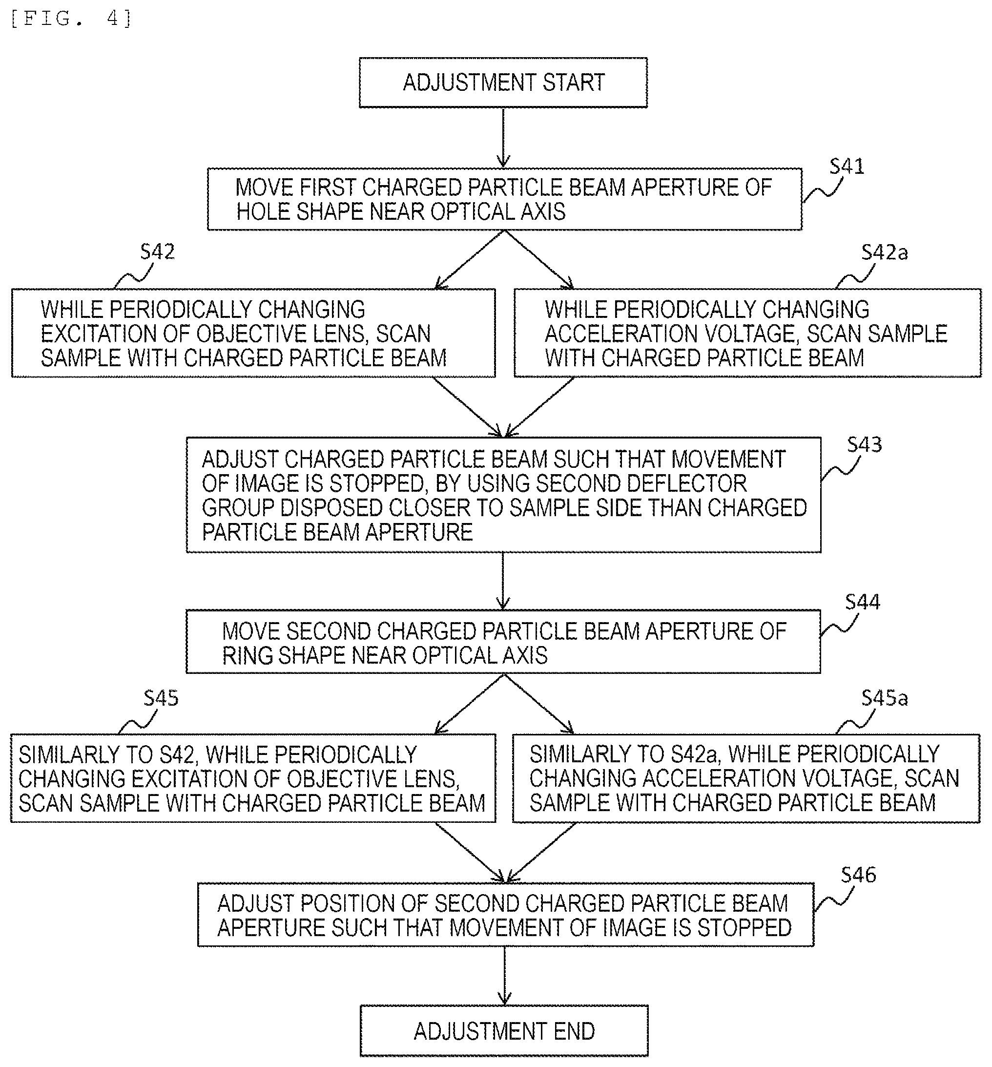
[0017] FIG. 4 is a flowchart showing a second adjustment procedure.
[0018] FIG. 5 is a flowchart showing a third adjustment procedure.
DESCRIPTION OF EMBODIMENTS
[0019] An embodiment of the present invention will be described with reference to the drawings. However, the present embodiment is only an example for realizing the present invention. In each drawing, the same reference numerals are given to the same components.
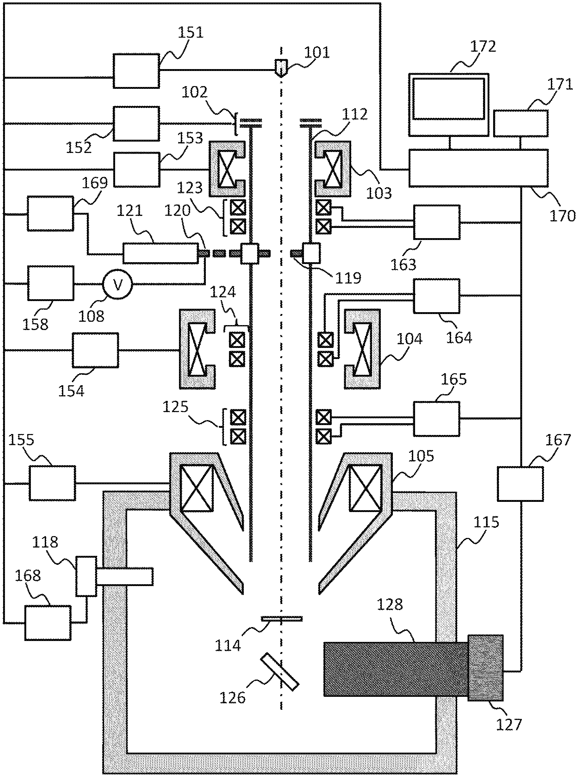
[0020] FIG. 1 schematically shows a charged particle beam device. The charged particle beam device includes, as main components, a charged particle beam source 101 that generates a charged particle beam, an acceleration electrode 102 for accelerating the charged particle beam emitted from the charged particle beam source 101, a beam tube 112 disposed from the acceleration electrode 102 to the vicinity of the lower end of the objective lens 105, first and second condenser lenses 103 and 104 that focus the charged particle beam emitted from the charged particle beam source 101, a first charged particle beam aperture 119 having a hole shape that shields a part of charged particles emitted from the charged particle beam source 101, a second charged particle beam aperture 120 having a ring shape that shields a part of the charged particles emitted from the charged particle beam source 101, a charged particle beam aperture device 121 having a drive mechanism for moving the first and second charged particle beam apertures 119 and 120, a charged particle beam aperture power supply 108 that applies a voltage to the second charged particle beam aperture 120, a first deflector group 123 disposed closer to the charged particle beam source 101 than a charged particle beam aperture portion, a second deflector group 124 disposed closer to the sample than the charged particle beam aperture portion, a third deflector group 125 that scans the sample with a charged particle beam, an objective lens 105 that focuses the charged particle beam on the sample, a sample chamber 115 for placing a sample 114, a detector 118 that detects secondary charged particles emitted from the sample, a transmission pattern detection surface 126 for detecting a charged particle beam transmitted through the sample, a camera 127 that observes the pattern on the detection surface, and an optical lens 128 disposed between the detection surface and the camera. Further, controllers that control each component of the above-described charged particle optical system include a charged particle beam source controller 151 that controls the charged particle beam source 101, an accelerating electrode controller 152 that controlling the accelerating electrode 102, first and second condenser lens controllers 153 and 154 that control the first and second condenser lenses 103 and 104, a charged particle beam aperture controller 169 that controls the charged particle beam aperture device 121, a charged particle beam aperture power supply controller 158 that controls the charged particle beam aperture power supply 108, a first deflector group controller 163 that controls the first deflector group 123, a second deflector group controller 164 that controls the second deflector group 124, a third deflector group controller 165 that controls the third deflector group 125, an objective lens controller 155 that controls the objective lens 105, a detector controller 168 that controls the detector 118, and a camera controller 167 that controls the camera 127.
[0021] These controllers are controlled by an integrated computer 170 that controls the operation of the entire charged particle beam device and constructs a charged particle beam image. The integrated computer 170 is connected to a controller (a keyboard, a mouse, or the like) 171 and a display 172. The operator inputs various instructions such as irradiation conditions, voltage conditions of the charged particle beam aperture and position conditions from the controller 171, and the acquired image and the control screen can be displayed on the display 172.
[0022] In the example of FIG. 1, two condenser lenses 103 and 104 are provided, but the number of condenser lenses is not limited for the purpose of controlling charged particles incident on the objective lens 105. The objective lens 105 is provided with a lens that does not leak a magnetic field outside the magnetic path, but may be a lens that leaks a magnetic field outside the magnetic path, or a compound objective lens having both a type that leaks a magnetic field and a type that does not leak a magnetic field. In addition, the condenser lenses 103 and 104 and the objective lens 105 may be an electrostatic lens for the above-described purpose, or may be an objective lens using both a magnetic lens and an electrostatic lens like a booster optical system or a retarding optical system. There is no limitation on the type of lens for the purpose of focusing the charged particle beam on the sample 114.
[0023] When a voltage is not applied to the second charged particle beam aperture 120, the charged particle beam aperture power supply 108 and the charged particle beam aperture power supply controller 158 for controlling the same are not required. Similarly, when the transmission image is not observed, the transmission pattern detection surface 126, the camera 127, the optical lens 128, and the camera controller 167 that controls the camera 127 becomes unnecessary.
[0024] In FIG. 1, the beam tube 112 is generally set to a GND potential (reference potential), but a predetermined voltage is applied to the booster optical system. For the purpose of covering the path of the charged particle beam, the shape and the number of constituent members are not limited. Further, the detector 118 that detects the secondary charged particles may be disposed in the sample chamber 115 as shown in FIG. 1, or may be disposed in a column on which the charged particle optical system is mounted. Further, the detector 118 may be disposed both in the sample chamber 115 and the inside of the column. For the purpose of detecting the secondary charged particles, the number of the detectors 118 and the location thereof are not limited. Although FIG. 1 shows a charged particle beam device including one charged particle beam column, a composite charged particle beam device including a plurality of charged particle beam columns may be used.
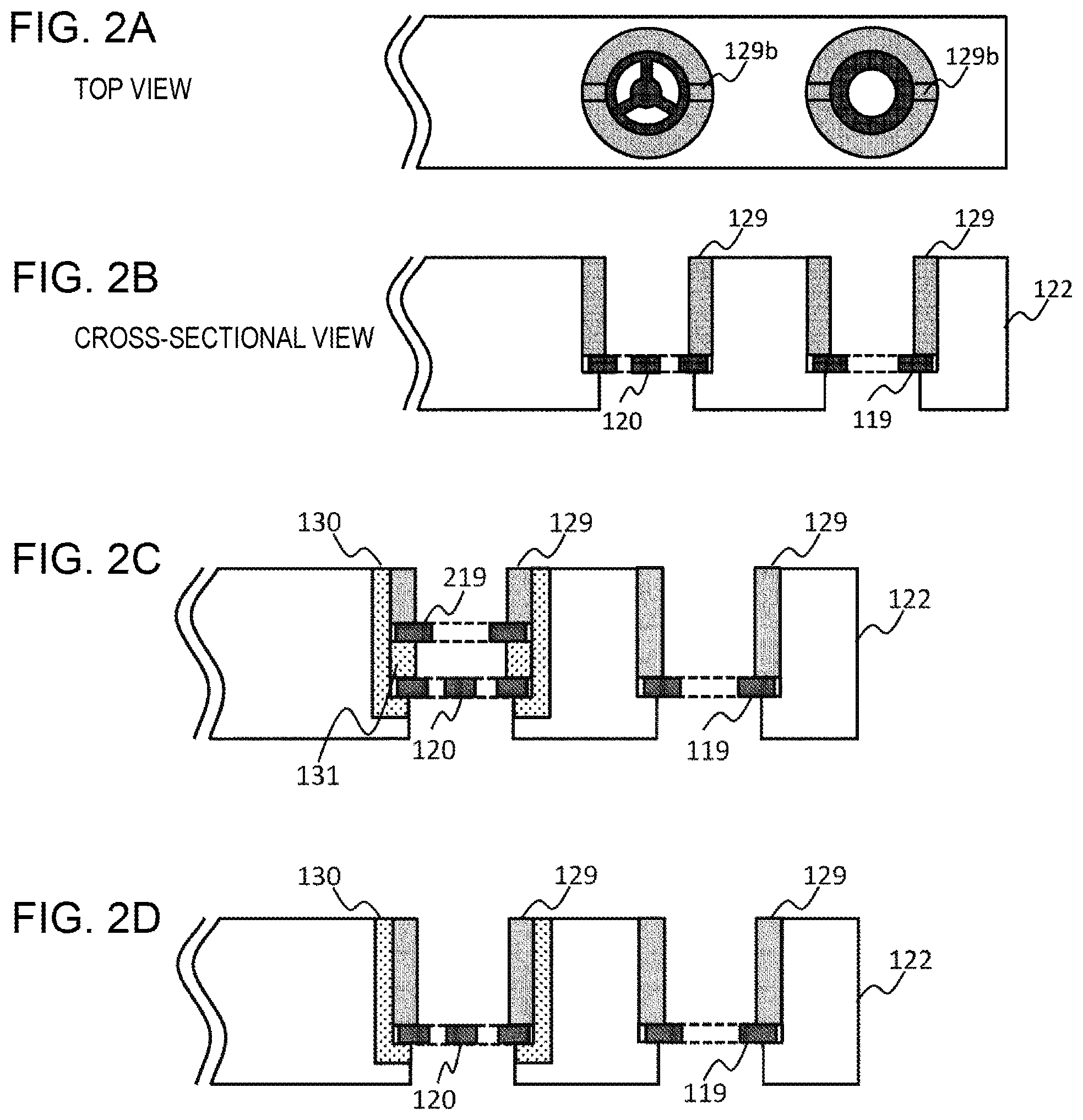
[0025] The configuration of the charged particle beam aperture portion will be described with reference to FIGS. 2A to 2D. As shown in FIG. 2A, a first charged particle beam aperture 119 having a hole shape and a second charged particle beam aperture 120 having a ring shape are supported by a charged particle stop support base 122. (a) is a top view, (b) is a cross-sectional view, and the charged particle beam apertures 119 and 120 are fixed to the support base 122 by the pressure screws 129, respectively. The groove 129b of the thread 129 seen from the top view is provided for screwing the pressure screw 129 into the recess of the support base 122. Modifications of the charged particle beam aperture device are shown below, but the top views are substantially the same, and are omitted.
[0026] As described in PTL 1, 2B has an aberration correction function by superimposing the hole-shaped charged particle beam aperture 219 on a ring-shaped charged particle beam aperture 120 along the optical axis direction of the charged particle beam, and applying a voltage between the two stops. In this case, in order to make the ring-shaped charged particle beam aperture 120 and the hole-shaped charged particle beam aperture 219 which are overlapped have different potentials, the two apertures are supported by the support base 122 via the insulating material 130 and the ring-shaped charged particle beam aperture 120 and the hole-shaped charged particle beam aperture 219 are insulated by the insulating spacer 131. In order to generate a voltage between the two apertures, a voltage may be applied to the hole-shaped charged particle beam aperture 219 via the pressure screw 129.
[0027] In the example of FIG. 1, the charged particle beam aperture power supply 108 that applies a voltage to the ring-shaped second charged particle aperture 120 is provided, but as illustrated in FIG. 2A, the first charged particle beam aperture 119 and the second charged particle beam aperture 120 may be electrically connected to each other via a conductive support base 122, and as illustrated in FIG. 2C, the second charged particle beam aperture 120 may be fixed to the support base 122 via the insulating material 130.
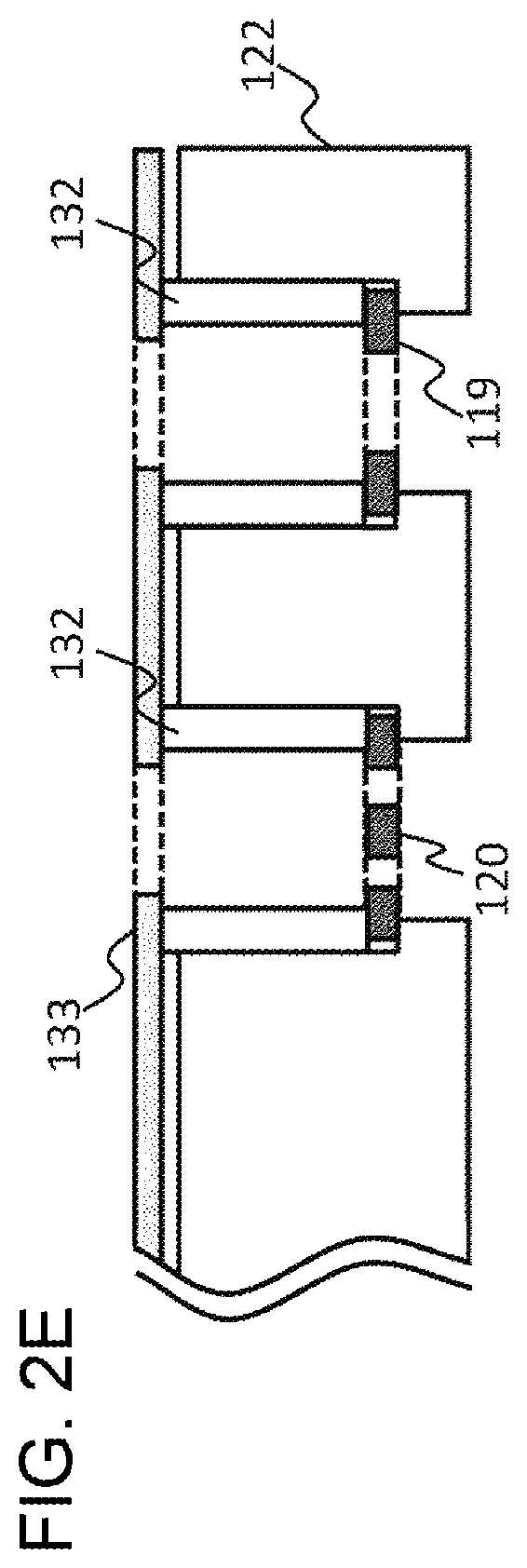
[0028] Further, the method of fixing the stop is not limited to the fixing method using the pressure screw 129, and the stop may be fixed by the spacer 132 and the pressing plate 133 as shown in FIG. 2D. The drive mechanism of the charged particle beam aperture device 121 switches between the first charged particle beam aperture 119 and the second charged particle beam aperture 120 by moving the support base 122, and adjusts the position of each aperture. The movement of the support base 122 may be performed by manual driving or electric driving including a stepping motor or a piezo element.
[0029] A method for adjusting a charged particle beam aperture having a ring shape will be described. In the present embodiment, first, necessary adjustments to obtain a charged particle beam image including the optical axis adjustment of the charged particle beam is performed on the first charged particle beam aperture 119 having a hole shape. Since the hole shape of the aperture is the general shape of a charged particle beam aperture, this adjustment is an operation normally performed by a user with a general charged particle beam device. Next, the charged particle beam aperture is changed from the first charged particle beam aperture 119 having a hole shape to the second charged particle beam aperture 120 having a ring shape. At this time, the second charged particle beam aperture 120 is disposed based on the position where the hole-shaped first charged particle beam aperture 119 is disposed. Thus, the user can acquire a charged particle beam image using the ring aperture without performing a difficult operation. The specific adjustment procedure will be described below. In these adjustment procedures, each controller of the charged particle optical system is controlled and executed by the integrated computer 170.
[0030] (1) First Adjustment Procedure
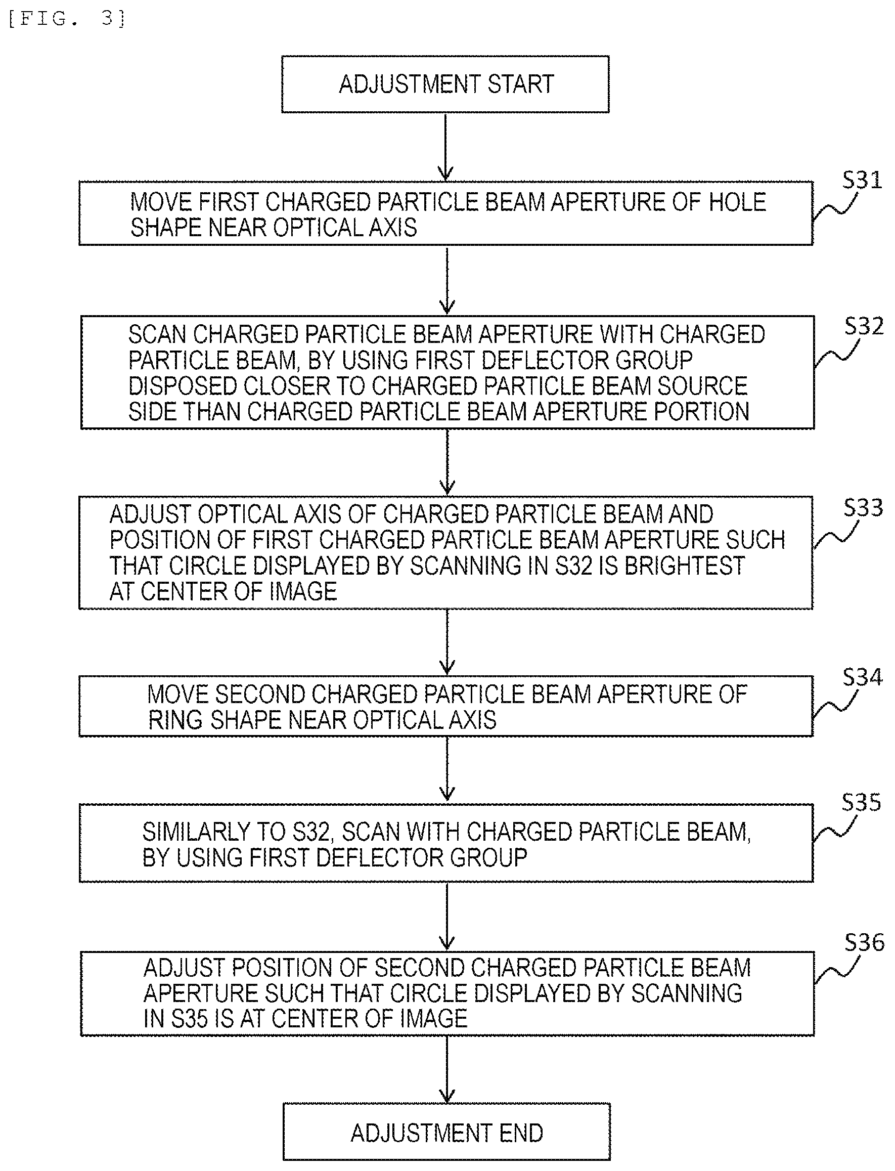
[0031] The first adjustment procedure will be described with reference to FIG. 3. First, the first charged particle beam aperture 119 having a hole shape is moved near the optical axis of the charged particle beam (step 31). The charged particle beam is applied by using the first deflector group 123 disposed closer to the charged particle beam source 101 side than the charged particle beam aperture device (step 32). This corresponds to the scanning the charged particle beam aperture with the charged particle beam.
[0032] Therefore, the output of the detector 118 is large (bright) when the hole of the aperture is scanned with the charged particle beam, and the output of the detector 118 is small (dark) when parts other than the hole are scanned with the charged particle beam. Therefore, when an image is displayed based on the scanning position of the charged particle beam, a circular image (charged particle beam image) is displayed. The optical axis of the charged particle beam and the position of the first charged particle beam aperture are adjusted such that the circle displayed by the scanning in step 32 becomes the brightest at the center of the image (observation field of view) (step 33). This corresponds to the position adjustment of the charged particle beam aperture performed in a general charged particle beam device.
[0033] Next, the second charged particle beam aperture 120 having a ring shape is moved near the optical axis of the charged particle beam (step 34), and as in step 32, the charged particle beam is applied by using the first deflector group 123 (step 35). On the charged particle beam aperture, the beam diameter of the charged particle beam is wider than the diameter of the charged particle beam aperture, so the image displayed based on the scanning position of the charged particle beam is a circular image (charged particle beam image), regardless of the aperture shape, as in the case of the first charged particle beam aperture. The position of the second charged particle beam aperture is adjusted such that the circle displayed by the scanning in step 35 is at the center of the image (observation field of view) (step 36). In step 33, the optical axis of the charged particle beam is adjusted to pass through the center of the first charged particle beam aperture 119. Therefore, the reason why a circular image (charged particle beam image) displayed when the first charged particle beam aperture is replaced with the second charged particle beam aperture and the charged particle beam is applied by the first deflector group 123 is not at the center of the image (observation field of view) is that the second charged particle beam aperture is not at the position where the first charged particle beam aperture has been located. Therefore, by adjusting the position of the second charged particle beam aperture 120 such that the circular image is brought to the center of the image, the second charged particle beam aperture 120 is adjusted to come to the position where the first charged particle beam aperture 119 has been located. At this time, the circular image that comes to the center is not always the position where the image becomes brightest.
[0034] (2) Second Adjustment Procedure
[0035] The second adjustment procedure will be described with reference to FIG. 4. In order to adjust the optical axis of the charged particle beam device more accurately than in the first adjustment procedure, after adjusting the charged particle beam aperture having the ring shape in the first adjustment procedure, fine adjustment may be performed in the second adjustment procedure.
[0036] First, the first charged particle beam aperture 119 having a hole shape is moved near the optical axis (step 41). The sample is scanned with the charged particle beam by the third deflector group 125 while periodically changing the excitation of the objective lens 105 (step 42). At this time, if the optical axis does not pass through the center of the objective lens 105, the center of the displayed image moves in synchronization with the excitation fluctuation of the objective lens 105. Then, the path of the charged particle beam is adjusted using the second deflector group 124 disposed closer to the sample side than the charged particle beam aperture such that the movement of the image is stopped (step 43). The state in which the movement of the image has stopped corresponds to the charged particle beam passing through the center of the objective lens 105.
[0037] Next, the second charged particle beam aperture 120 having a ring shape is moved near the optical axis (step 44). Similarly to step 42, the sample is scanned with the charged particle beam while periodically changing the excitation of the objective lens 105 (step 45) This time, the position of the second charged particle beam aperture 120 is adjusted such that the movement of the image is stopped (step 46). This means that the optical axis of the charged particle beam in a state where the first charged particle beam aperture 119 is inserted is adjusted to pass through the center of the second charged particle beam aperture 120.
[0038] In steps 42 and 45 described above, a similar adjustment can be performed, by periodically changing the acceleration voltage of the charged particle beam by the charged particle beam source controller 151, instead of periodically changing the excitation of the objective lens 105 (steps 42a and 45a).
[0039] (3) Third Adjustment Procedure
[0040] The third adjustment procedure will be described with reference to FIG. 5. In the third adjustment procedure, adjustment is performed using a transmission pattern. In order to adjust the optical axis of the charged particle beam device more accurately than in the first adjustment procedure, after adjusting the charged particle beam aperture having the ring shape in the first adjustment procedure, fine adjustment may be performed in the third adjustment procedure.
[0041] First, the first charged particle beam aperture 119 having a hole shape is moved near the optical axis (step 51). Spot-irradiation of the charged particle beam is performed on one point on the sample, and the transmission pattern is displayed using the transmission pattern detection surface 126 below the sample, the lens 128, and the camera 127 (step 52). In this case, the shape of the transmission pattern is circular.
[0042] The pattern displayed in step 52 expands and contracts in conjunction with the excitation fluctuation of the objective lens 105, that is, the change in focus of the charged particle beam. While changing the focus, the position of the first charged particle beam aperture 119 is adjusted such that the transmission pattern uniformly expands and contracts concentrically (step 53). The state in which the change of the pattern is concentrically uniform corresponds to the coincidence of the optical axis of the charged particle beam and the center of the charged particle beam aperture.
[0043] Next, the second charged particle beam aperture 120 having a ring shape is moved near the optical axis (step 54). Similar to step 52, spot-irradiation of the charged particle beam is performed on one point on the sample and a transmission pattern is displayed (step 55). In this case, the shape of the transmission pattern is a ring shape. The position of the second charged particle beam aperture 119 is adjusted such that the center of the transmission pattern in the state of step 53 matches the center of the transmission pattern when the second charged particle beam aperture 119 is inserted in step 55 (step 56). This means that the optical axis of the charged particle beam in a state where the first charged particle beam aperture 119 is inserted is adjusted to pass through the center of the second charged particle beam aperture 120.
[0044] In step 53 described above, instead of adjusting the position of the first charged particle beam aperture 120, similar adjustment can be performed by adjusting the path of the charged particle beam to make the change of the transmission pattern concentrically uniform, by using the second deflector group 124 disposed closer to the sample side than the charged particle beam aperture portion (step 53a).
[0045] The first to third adjustment procedures have been described above. In these adjustment procedures, the aperture may be moved manually, but it is more convenient if the charged particle beam aperture device provided with an electric drive function can be controlled by the controller provided in the charged particle beam device. As one example of realizing the electric drive mechanism, it is conceivable that a large movement such as switching between the first charged particle beam aperture 119 and the second charged particle beam aperture 120 is performed by a stepping motor and the movement requiring fine adjustment accuracy such as adjusting the position of each charged particle beam aperture is performed by a piezo element. Further, a configuration of using a stepping motor or a piezo element for large movement and a stepping motor or a piezo element for fine adjustment may be employed. Alternatively, both large movement and highly accurate movement may be achieved by using a single stepping motor or piezo element. For the purpose of realizing the electric drive mechanism, any means may be used.
[0046] Further, the position of the charged particle beam aperture is stored, the position of the charged particle beam aperture is displayed on the display 172, or the position of the second charged particle beam aperture 120 adjusted in advance is stored, the charged particle beam aperture device 121 may set the second charged particle beam aperture 120 in the stored position, only by the user selecting the second charged particle beam aperture. Thereby, the user can easily perform observation or processing using the charged particle beam aperture disposed at the optimal position, and usability can be improved.
REFERENCE SIGNS LIST
[0047] 101: Charged particle beam source [0048] 102: Acceleration electrode [0049] 103: First condenser lens [0050] 104: Second condenser lens [0051] 105: Objective lens [0052] 108: Charged particle beam aperture power supply [0053] 112: Beam tube [0054] 114: Sample [0055] 115: Sample chamber [0056] 118: Detector [0057] 119: First charged particle beam aperture having hole shape [0058] 120: Second charged particle beam aperture having ring shape [0059] 121: Charged particle beam aperture device [0060] 123: First deflector group [0061] 124: Second deflector group [0062] 125: Third deflector group [0063] 126: Transmission pattern detection surface [0064] 127: Camera [0065] 128: Optical lens [0066] 129: Pressure screw [0067] 130: Insulation material [0068] 131: Insulating spacer [0069] 132: Spacer [0070] 133: Pressing plate [0071] 151: Charged particle source controller [0072] 152: Accelerator electrode controller [0073] 153: First condenser lens controller [0074] 154: Second condenser lens controller [0075] 155: Objective lens controller [0076] 158: Charged particle beam aperture power controller [0077] 163: First deflector group controller [0078] 164: Second deflector group controller [0079] 165: Third deflector group controller [0080] 167: Camera controller [0081] 168: Detector controller [0082] 169: Charged particle beam aperture controller [0083] 170: Integrated computer [0084] 171: Controller [0085] 172: Display
* * * * *
D00000
D00001
D00002
D00003
D00004
D00005
D00006
XML
uspto.report is an independent third-party trademark research tool that is not affiliated, endorsed, or sponsored by the United States Patent and Trademark Office (USPTO) or any other governmental organization. The information provided by uspto.report is based on publicly available data at the time of writing and is intended for informational purposes only.
While we strive to provide accurate and up-to-date information, we do not guarantee the accuracy, completeness, reliability, or suitability of the information displayed on this site. The use of this site is at your own risk. Any reliance you place on such information is therefore strictly at your own risk.
All official trademark data, including owner information, should be verified by visiting the official USPTO website at www.uspto.gov. This site is not intended to replace professional legal advice and should not be used as a substitute for consulting with a legal professional who is knowledgeable about trademark law.