Loop Heat Pipe Structure
Lin; Yuan-Yi
U.S. patent application number 17/068535 was filed with the patent office on 2021-01-28 for loop heat pipe structure. The applicant listed for this patent is ASIA VITAL COMPONENTS (CHINA) CO., LTD.. Invention is credited to Yuan-Yi Lin.
| Application Number | 20210025658 17/068535 |
| Document ID | / |
| Family ID | 1000005149246 |
| Filed Date | 2021-01-28 |


View All Diagrams
| United States Patent Application | 20210025658 |
| Kind Code | A1 |
| Lin; Yuan-Yi | January 28, 2021 |
LOOP HEAT PIPE STRUCTURE
Abstract
A loop heat pipe structure includes an evaporator internally defining a vaporization chamber, in which a first wick structure is provided and a working fluid is filled; at least one vapor pipe having a first end and a second end, and the first end being communicable with an end of the evaporator; and at least one liquid pipe having a third end and a fourth end, the third end being communicable with the second end of the at least one vapor pipe and forming a condensing section, and the fourth end being communicable with another end of the evaporator. The evaporator, the at least one vapor pipe and the at least one liquid pipe together form a loop for the working fluid; and a grand total cross sectional area of the at least one vapor pipe is larger than that of the at least one liquid pipe.
| Inventors: | Lin; Yuan-Yi; (Shenzhen, CN) | ||||||||||
| Applicant: |
|
||||||||||
|---|---|---|---|---|---|---|---|---|---|---|---|
| Family ID: | 1000005149246 | ||||||||||
| Appl. No.: | 17/068535 | ||||||||||
| Filed: | October 12, 2020 |
Related U.S. Patent Documents
| Application Number | Filing Date | Patent Number | ||
|---|---|---|---|---|
| 15821719 | Nov 22, 2017 | |||
| 17068535 | ||||
| Current U.S. Class: | 1/1 |
| Current CPC Class: | F28D 15/043 20130101 |
| International Class: | F28D 15/04 20060101 F28D015/04 |
Claims
1. A loop heat pipe structure, comprising: an evaporator internally defining a vaporization chamber, in which a first wick structure is provided and a working fluid is filled; a plurality of vapor pipes each having a first end and a second end, and the first end being communicable with one end of the evaporator; and at least one liquid pipe having a third end and a fourth end, the third end being communicable with the second end of the plurality of vapor pipes and forming a condensing section, and the fourth end being communicable with another end of the evaporator; and the evaporator, the plurality of vapor pipes and the liquid pipes together forming a loop for the working fluid; and where a grand total cross sectional area of the plurality of vapor pipes is larger than a grand total cross sectional area of the at least one liquid pipe.
2. The loop heat pipe structure as claimed in claim 1, wherein the condensing section is diametrically expanded and internally defines a condensation chamber, which has an end communicable with the second end of the plurality of vapor pipes and another end communicable with the third end of the at least one liquid pipe.
3. The loop heat pipe structure as claimed in claim 1, wherein the at least one liquid pipe is internally provided with a second wick structure.
4. The loop heat pipe structure as claimed in claim 3, wherein the condensing section is internally provided with a third wick structure, and the third wick structure being capillarily connected to the second wick structure.
5. The loop heat pipe structure as claimed in claim 1, wherein the condensing section is externally provided with a radiation fin assembly.
6. The loop heat pipe structure as claimed in claim 1, wherein the first wick structure separates the vaporization chamber into a liquid chamber and a vapor chamber; the liquid chamber being located adjacent to the fourth end of the at least one liquid pipe and storing the working fluid that is in a liquid phase, and the vapor chamber being located adjacent to the first end of the plurality of vapor pipes and allowing the working fluid in a gas phase to flow therethrough; and the first wick structure including a plurality of grooves, via which the gas-phase working fluid flowing to the vapor chamber.
7. The loop heat pipe structure as claimed in claim 1 wherein there are two liquid pipes.
8. The loop heat pipe structure as claimed in claim 2 wherein there are two liquid pipes.
9. The loop heat pipe structure as claimed in claim 6 wherein there are two liquid pipes.
Description
[0001] The present application is a continuation in part of U.S. patent application Ser. No. 15/821,719, filed on Nov. 22, 2017.
FIELD OF THE INVENTION
[0002] The present invention relates to a loop heat pipe structure, and more particularly to a loop heat pipe structure that increases the amount of gas-phase working fluid flowing out of an evaporator of the loop heat pipe structure.
BACKGROUND OF THE INVENTION
[0003] While the currently available electronic apparatus have increasingly upgraded performance, the electronic elements of these high-performance electronic apparatus for signal processing and data computing also produce more heat than the electronic elements of the conventional electronic apparatus. Generally, the most commonly adopted heat dissipation elements include heat pipes, heat sinks and vapor chambers. These heat dissipation elements are so arranged that they are in direct contact with the heat-producing electronic elements in order to provide further enhanced heat dissipation effect and prevent the electronic elements from being burnt out due to overheating. In many cases, fans with forced heat dissipation effect are further used to cool the heat-producing electronic elements. While the fans indeed enable upgraded heat dissipation effect, they are not always suitable for use with the electronic apparatus that have a limited or narrow internal space. Therefore, the space available in the electronic apparatus is also a key point to be considered in designing a heat dissipation system. Recently, the concept of gas-liquid circulation in a heat pipe has been utilized to develop a loop heat pipe structure (LHP), which is a loop module consisting of a vaporization chamber and a condensation device fluid-communicably connected to each other via a pipe, through which a working fluid flows.
[0004] The pipe in the above-described conventional loop heat pipe structure for connecting the vaporization chamber to the condensation device can be divided into two sections, namely, a vapor pipe extended from a vapor outlet of the vaporization chamber to the condensation device and a liquid pipe extended from the condensation device to an inlet of the vaporization chamber. In the conventional loop heat pipe structure, the vapor pipe and the liquid pipe are the same in pipe size. That is, the conventional vapor pipe does not provide more space for the working fluid in gas phase to flow therethrough. Since the gas-phase working fluid has a density lower than that of the working fluid in liquid-phase, the flow of the gas-phase working fluid is lower than that of the same amount of liquid-phase working fluid. Therefore, the amount of the liquid-phase working fluid flowing back to the vaporization chamber is higher than that of the gas-phase working fluid flowing out of the vaporization chamber. As a result, the gas-phase working fluid in the vaporization chamber could not be quickly delivered via the vapor pipe to the condensation device for condensing into the liquid-phase working fluid while the condensed liquid-phase working fluid has already flowed from the condensation device back to the vaporization chamber. In other words, the vapor is blocked in the vaporization chamber to cause lowered overall heat dissipation effect of the loop heat pipe structure.
[0005] It has been the intention of the inventor to develop an improved loop heat pipe structure to overcome the blocking problem in the conventional loop heat pipe structure.
SUMMARY OF THE INVENTION
[0006] To effectively solve the problem in the conventional loop heat pipe structure, a primary object of the present invention is to provide an improved loop heat pipe structure that enables an increased amount of out-going gas-phase working fluid, so that the flow of the gas-phase working fluid and of the liquid-phase working fluid in the loop heat pipe structure are almost the same to thereby largely upgrade the cooling effect of the loop heat pipe structure.
[0007] To achieve the above and other objects, the loop heat pipe structure according to the present invention includes an evaporator, at least one vapor pipe and at least one liquid pipe. The evaporator internally defines a vaporization chamber, in which a first wick structure is provided and a working fluid is filled. The at least one vapor pipe has a first end and a second end, and the first end is communicable with an end of the evaporator. The at least one liquid pipe has a third end and a fourth end, the third end is communicable with the second end of the at least one vapor pipe and forms a condensing section, and the fourth end is communicable with another end of the evaporator. The evaporator, the at least one vapor pipe and the at least one liquid pipe form a loop for the working fluid. A grand total cross sectional area of the at least one vapor pipe is larger than a grand total cross sectional area of the at least one liquid pipe.
[0008] According to an embodiment of the present invention, at least one of the first end and the second end of the at least one vapor pipe is formed of a plurality of communicating pipes.
[0009] According to an embodiment of the present invention, the condensing section internally defines a condensation chamber, which has an end communicable with the second end of the at least one vapor pipe and another end communicable with the third end of the at least one liquid pipe.
[0010] According to an embodiment of the present invention, the condensing section consists of a plurality of condensing pipes, each of which has an end communicable with the second end of the at least one vapor pipe and another end communicable with the third end of the at least one liquid pipe.
[0011] According to an embodiment of the present invention, the at least one liquid pipe is internally provided with a second wick structure.
[0012] According to an embodiment of the present invention, the condensing section is internally provided with a third wick structure, and the third wick structure is capillarily connected to the second wick structure.
[0013] According to an embodiment of the present invention, the condensing section is externally provided with a radiation fin assembly.
[0014] According to an embodiment of the present invention, the first wick structure separates the vaporization chamber into a liquid chamber and a vapor chamber. The liquid chamber is located adjacent to the fourth end of the at least one liquid pipe and stores the working fluid that is in a liquid phase, and the vapor chamber is located adjacent to the first end of the at least one vapor pipe and allows the working fluid in a gas phase to flow therethrough. Further, the first wick structure includes a plurality of grooves, via which the gas-phase working fluid flows to the vapor chamber.
[0015] According to the present invention, the grand total of the cross-sectional areas of the vapor pipes is larger than that of the liquid pipes. With this design, the amount of the out-going gas-phase working fluid from the evaporator can be increased, making the flow of the gas-phase working fluid and of the liquid-phase working fluid almost the same and accordingly, enabling the loop heat pipe structure of the present invention to have largely upgraded heat dissipation effect.
BRIEF DESCRIPTION OF THE DRAWINGS
[0016] The structure and the technical means adopted by the present invention to achieve the above and other objects can be best understood by referring to the following detailed description of the preferred embodiments and the accompanying drawings, wherein
[0017] FIG. 1 is a fragmentary sectional top view of a loop heat pipe structure according to a first embodiment of the present invention, showing an evaporator thereof;
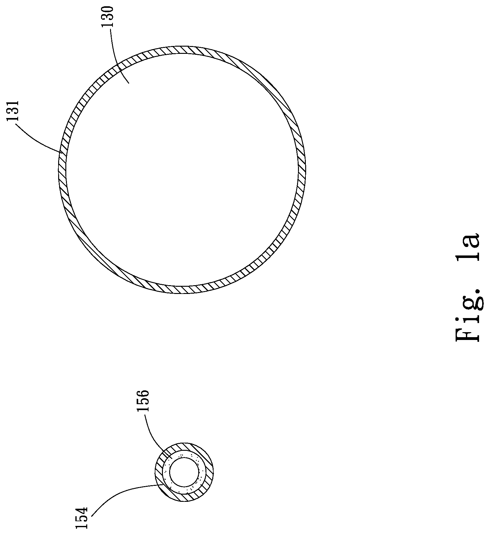
[0018] FIG. 1a includes sectional views taken along two lines A-A of FIG. 1, showing the cross-sectional areas of a vapor pipe and a liquid pipe of the evaporator of FIG. 1;
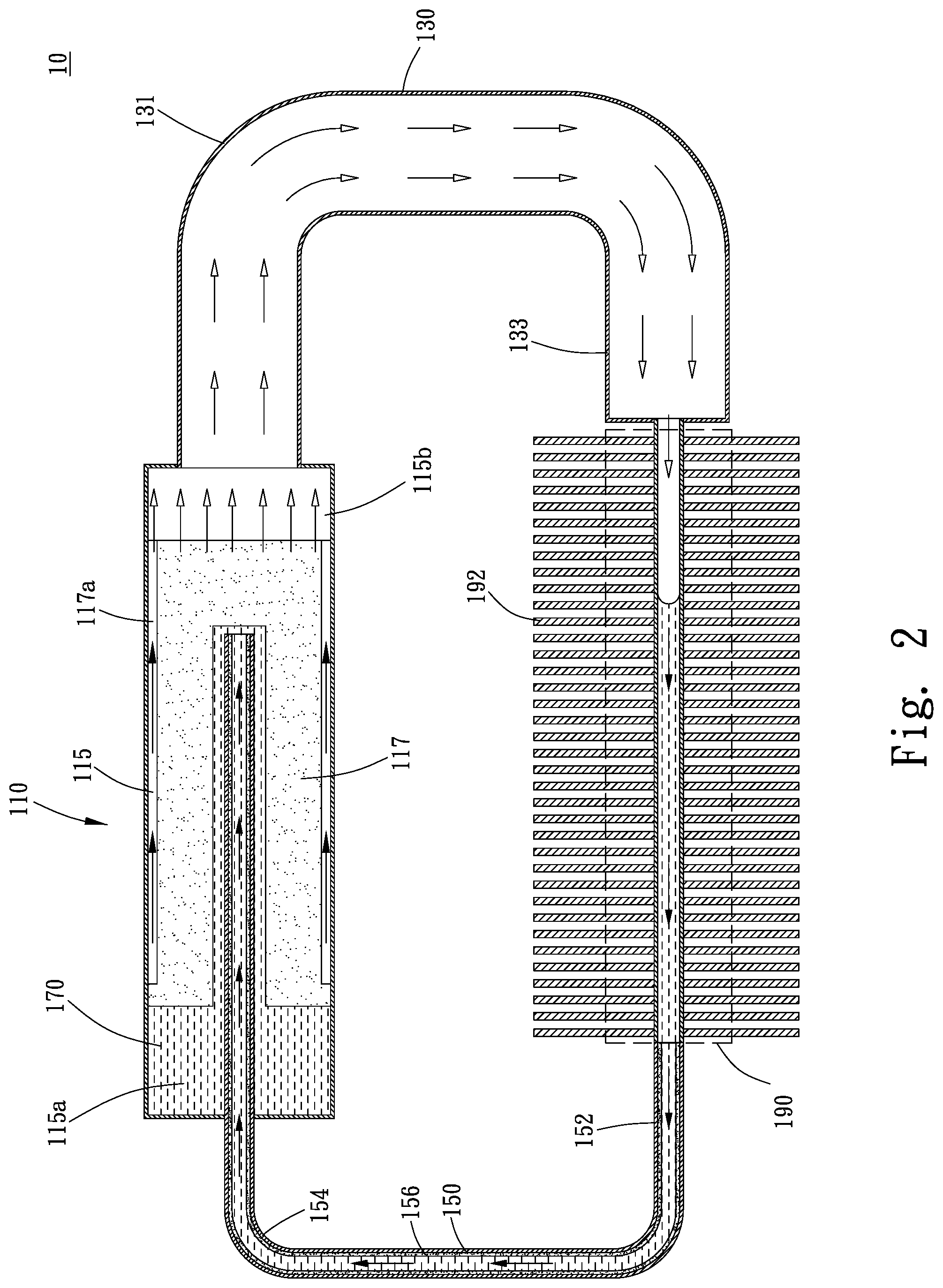
[0019] FIG. 2 is a complete sectional top view of the loop heat pipe structure according to the first embodiment of the present invention;
[0020] FIG. 3 is a sectional top view of a loop heat pipe structure according to a second embodiment of the present invention;
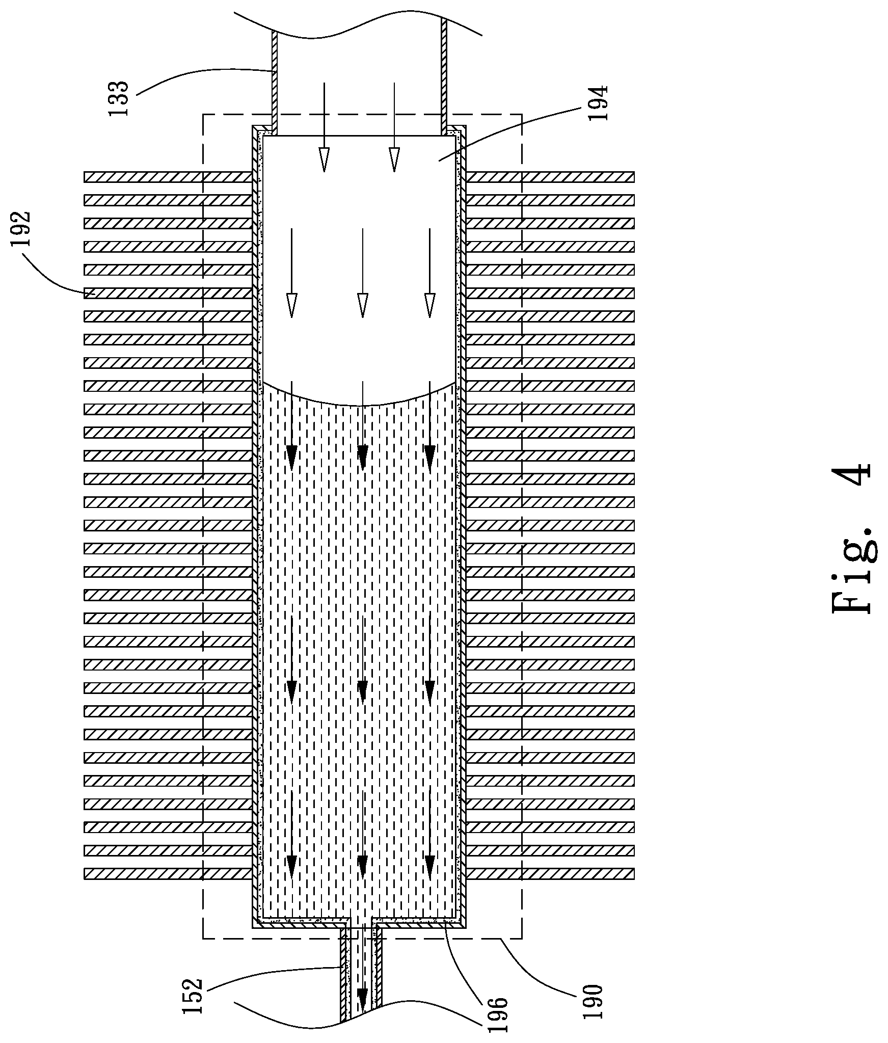
[0021] FIG. 4 is a fragmentary sectional top view showing a condensing section for the loop heat pipe structure according to the second embodiment of the present invention;
[0022] FIG. 5 is a sectional top view of a loop heat pipe structure according to a third embodiment of the present invention;
[0023] FIG. 6 is a sectional top view of a loop heat pipe structure according to a fourth embodiment of the present invention;
[0024] FIG. 7 is a sectional top view of a loop heat pipe structure according to a fifth embodiment of the present invention;
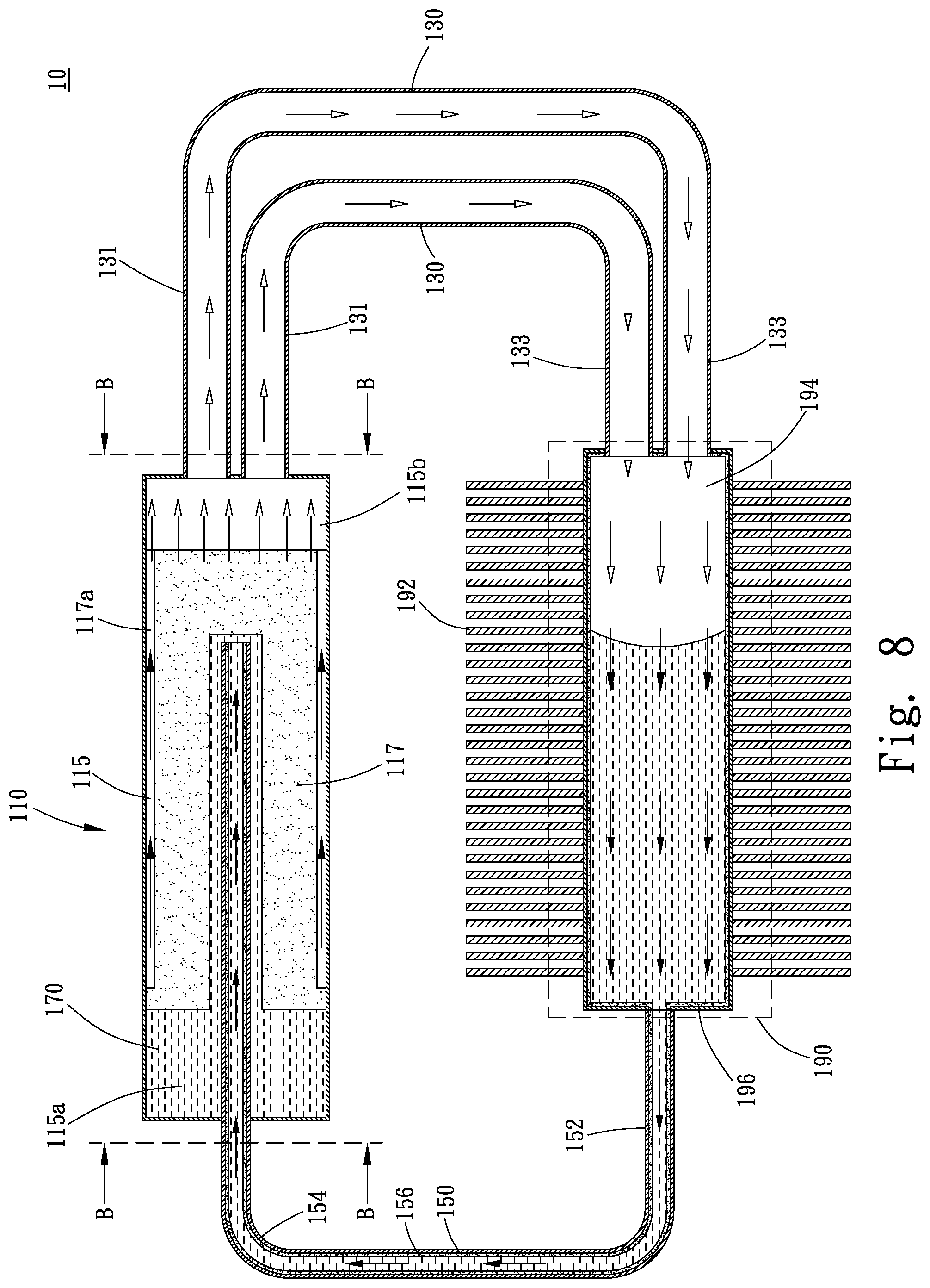
[0025] FIG. 8 is a sectional top view of a loop heat pipe structure according to a sixth embodiment of the present invention;
[0026] FIG. 8a includes sectional views taken along two lines B-B of FIG. 8, showing the cross-sectional areas of a plurality of vapor pipes and a liquid pipe of the loop heat pipe structure according to the sixth embodiment of the present invention;
[0027] FIG. 9 is a sectional top view of a loop heat pipe structure according to a seventh embodiment of the present invention; and
[0028] FIG. 9a includes sectional views taken along two lines C-C of FIG. 9, showing the cross-sectional areas of a plurality of vapor pipes and a plurality of liquid pipes of the loop heat pipe structure according to the seventh embodiment of the present invention.
DETAILED DESCRIPTION OF THE PREFERRED EMBODIMENTS
[0029] The present invention will now be described with some preferred embodiments thereof and by referring to the accompanying drawings. For the purpose of easy to understand, elements that are the same in the preferred embodiments are denoted by the same reference numerals.
[0030] Please refer to FIG. 2 which is a complete sectional top view of a loop heat pipe structure 10 according to a first embodiment of the present invention. As shown, the loop heat pipe structure 10 in the first embodiment includes an evaporator 110, at least one vapor pipe 130, and at least one liquid pipe 150. FIG. 1 is a fragmentary sectional top view of the loop heat pipe structure 10 of FIG. 2, showing the evaporator 110; and FIG. 1a includes sectional views taken along two lines A-A of FIG. 1, showing the cross-sectional areas of the vapor pipe 130 and the liquid pipe 150 of the evaporator 110 of FIG. 1.
[0031] The evaporator 110 internally defines a vaporization chamber 115, in which a first wick structure 117 is provided and a working fluid 170 is filled. In the illustrated first embodiment, the first wick structure 117 separates the vaporization chamber 115 into a liquid chamber 115a and a vapor chamber 115b. The liquid chamber 115a is located adjacent to the at least one liquid pipe 150 and stores the working fluid 170 that is in a liquid phase. The vapor chamber 115b is located adjacent to the at least one vapor pipe 130 and allows the working fluid 170 in a gas phase to flow therethrough. The first wick structure 117 includes a plurality of grooves 117a, via which the gas-phase working fluid 170 flows to the vapor chamber 115b.
[0032] The at least one vapor pipe 130 has a first end 131 and a second end 133 located at two opposite ends of the vapor pipe 130. The first end 131 of the vapor pipe 130 is communicable with an end of the vaporization chamber 115 of the evaporator 110 having the vapor chamber 115b. In the illustrated first embodiment, there is only one vapor pipe 130 connected to the vaporization chamber 115 of the evaporator 110 and the first end 131 of the vapor pipe 130 is directly communicable with the vaporization chamber 115.
[0033] The at least one liquid pipe 150 has a third end 152 and a fourth end 154 located at two opposite ends of the liquid pipe 150. The third end 152 of the liquid pipe 150 is communicable with the second end 133 of the vapor pipe 130, and the fourth end 154 of the liquid pipe 150 is communicable with another end of the evaporator 110 having the liquid chamber 115a. With these arrangements, the evaporator 110, the vapor pipe 130 and the liquid pipe 150 together form a loop for the working fluid 170. Further, the at least one liquid pipe 150 is extended into the vaporization chamber 115. In the illustrated first embodiment, the at least one liquid pipe 150 has a second wick structure 156 provided therein. In the illustrated first embodiment, there is only one liquid pipe 150, which is communicable with the vapor pipe 130. A section of the third end 152 of the liquid pipe 150 that leads to and communicates with the second end 133 of the vapor pipe 130 is formed into a condensing section 190. A radiation fin assembly 192 is provided around an outer surface of the condensing section 190.
[0034] The vapor pipe 130 has a total cross-sectional area larger than that of the liquid pipe 150. As can be seen in FIG. 1a, in the illustrated first embodiment, the one single vapor pipe 130 has a total cross-sectional area larger than that of the one single liquid pipe 150.
[0035] In practical application of the present invention, the evaporator 110 is in contact with a heat source (not shown) to absorb heat produced by the heat source. The first wick structure 117 absorbs the liquid-phase working fluid 170 that flows into the liquid chamber 115a of the vaporization chamber 115. The evaporator 110 absorbs the heat from the heat source and the liquid-phase working fluid 170 in the first wick structure 117 is accordingly heated, vaporized and converted into a gas phase. The gas-phase working fluid 170 flows through the grooves 117a of the first wick structure 117 toward the vapor chamber 115b. The gas-phase working fluid 170 flows from the vapor chamber 115b into the vapor pipe 130 via the first end 131 thereof and keeps flowing toward the condensing section 190. The gas-phase working fluid 170 finally flows into the condensing section 190 via the second end 133 of the vapor pipe 130. Heat carried by the gas-phase working fluid 170 is absorbed by the condensing section 190 and the radiation fin assembly 192, from where the heat is radiated into ambient air. The gas-phase working fluid 170 is cooled and condensed at the condensing section 190 and converted into the liquid-phase working fluid 170 again to flow into the liquid pipe 150 via the third end 152 of the liquid pipe 150. The second wick structure 156 in the liquid pipe 150 enables the liquid-phase working fluid 170 to flow toward the fourth end 154 of the liquid pipe 150 more quickly. Finally, the liquid-phase working fluid 170 flows back into the liquid chamber 115a of the vaporization chamber 115 to start another cycle of gas-liquid circulation in the loop heat pipe structure 10.
[0036] According to the present invention, the total cross-sectional area of the vapor pipe or pipes 130 is larger than that of the liquid pipe or pipes 150. With this design, the amount of the out-going gas-phase working fluid 170 from the evaporator 110 can be increased to thereby increase the flow of the gas-phase working fluid 170 into the condensing section 190, making the flow of the gas-phase working fluid 170 and of the liquid-phase working fluid 170 almost the same and accordingly, enabling the loop heat pipe structure 10 of the present invention to have largely upgraded heat dissipation effect.
[0037] FIG. 3 is a sectional top view of a loop heat pipe structure 10 according to a second embodiment of the present invention, and FIG. 4 shows a condensing section 190 for the loop heat pipe structure 10 according to the second embodiment of the present invention. Please refer to FIGS. 3 and 4 along with FIGS. 1 and 2. As shown, the second embodiment is different from the first embodiment in that the condensing section 190 in the second embodiment is diametrically expanded and internally defines a condensation chamber 194, which has an end communicable with the second end 133 of the vapor pipe 130 and another end communicable with the third end 152 of the liquid pipe 150. Since all other structural and functional features of the second embodiment are similar to those of the first embodiment, they are not repeatedly described herein.
[0038] Further, in the illustrated second embodiment, the condensing section 190 is internally provided with a third wick structure 196, which is capillarily connected to the second wick structure 156. Herein, the description "is capillarily connected to" means the second and the third wick structure 156, 196 are in material contact or connection with each other, such that pores in the second wick structure 156 are communicable with pores in the third wick structure 196 and a capillary force of the third wick structure 196 can be transmitted or extended to the second wick structure 156, enabling the liquid-phase working fluid 170 to flow from the condensing section 190 back to the liquid chamber 115a due to the capillary force.
[0039] The condensation chamber 194 can receive and cool more gas-phase working fluid 170 at a time, and the capillary force of the second and third wick structures 156, 196 enables the liquid-phase working fluid 170 to more quickly flow back to the liquid chamber 115a. With these arrangements, the loop heat pipe structure 10 of the present invention can have largely upgraded heat dissipation effect.
[0040] FIG. 5 is a sectional top view of a loop heat pipe structure 10 according to a third embodiment of the present invention. Please refer to FIG. 5 along with FIGS. 3 and 4. As shown, the third embodiment is different from the second embodiment in that the condensing section 190 in the third embodiment consists of a plurality of condensing pipes 190a, which respectively have an end communicable with the second end 133 of the vapor pipe 130 and another end communicable with the third end 152 of the liquid pipe 150. Since all other structural and functional features of the third embodiment are similar to those of the second embodiment, they are not repeatedly described herein.
[0041] Since the plurality of condensing pipes 190a of the condensing section 190 can receive and cool more gas-phase working fluid 170 at a time, the loop heat pipe structure 10 of the present invention can have largely upgraded heat dissipation effect.
[0042] FIG. 6 is a sectional top view of a loop heat pipe structure 10 according to a fourth embodiment of the present invention. Please refer to FIG. 6 along with FIG. 5. As shown, the fourth embodiment is different from the third embodiment in that the first end 131 of the vapor pipe 130 in the fourth embodiment is formed of a plurality of communicating pipes 131a, which respectively have an end communicable with the vapor chamber 115b of the vaporization chamber 115 in the evaporator 110. Since all other structural and functional features of the fourth embodiment are similar to those of the third embodiment, they are not repeatedly described herein.
[0043] With the plurality of communicating pipes 131a at the first end 131 of the vapor pipe 130, the amount of the gas-phase working fluid 170 that can flow into the condensing section 190 at a time is increased, making the flow of the gas-phase working fluid 170 and of the liquid-phase working fluid 170 almost the same and accordingly, enabling the loop heat pipe structure 10 of the present invention to have largely upgraded heat dissipation effect.
[0044] FIG. 7 is a sectional top view of a loop heat pipe structure 10 according to a fifth embodiment of the present invention. Please refer to FIG. 7 along with FIG. 5. As shown, the fifth embodiment is different from the third embodiment in that the second end 133 of the vapor pipe 130 in the fifth embodiment is formed of a plurality of communicating pipes 133a, which respectively have an end communicable with the condensing section 190 and accordingly, the condensation chamber 194 defined in the condensing section 190. Since all other structural and functional features of the fifth embodiment are similar to those of the third embodiment, they are not repeatedly described herein.
[0045] With the plurality of communicating pipes 133a at the second end 133 of the vapor pipe 130, the amount of the gas-phase working fluid 170 that can flow into the condensing section 190 at a time is increased, making the flow of the gas-phase working fluid 170 and of the liquid-phase working fluid 170 almost the same and accordingly, enabling the loop heat pipe structure 10 of the present invention to have largely upgraded heat dissipation effect.
[0046] FIG. 8 is a sectional top view of a loop heat pipe structure 10 according to a sixth embodiment of the present invention, and FIG. 8a includes sectional views taken along two lines B-B of FIG. 8, showing the cross-sectional areas of a plurality of vapor pipes 130 and a liquid pipe 150 of the loop heat pipe structure 10 according to the sixth embodiment of the present invention. Please refer to FIGS. 8 and 8a along with FIG. 6. As shown, the sixth embodiment is different from the fourth embodiment in that a plurality of vapor pipes 130 is included in the sixth embodiment and these vapor pipes 130 are communicably connected at their first ends 131 to the vaporization chamber 115 of the evaporator 110 and at their second ends 133 to the condensation chamber 194 in the condensing section 190. Since all other structural and functional features of the sixth embodiment are similar to those of the fourth embodiment, they are not repeatedly described herein.
[0047] As can be seen in FIG. 8a, in the illustrated sixth embodiment, a grand total of the cross-sectional areas of the vapor pipes 130 is larger than the total cross-sectional area of the one single liquid pipe 150.
[0048] With the plurality of vapor pipes 130, an increased amount of gas-phase working fluid 170 can be guided out of the evaporator 110 into the condensation chamber 194 for cooling, enabling the loop heat pipe structure 10 of the present invention to have largely upgraded heat dissipation effect.
[0049] FIG. 9 is a sectional top view of a loop heat pipe structure 10 according to a seventh embodiment of the present invention, and FIG. 9a includes sectional views taken along two lines C-C of FIG. 9, showing the cross-sectional areas of a plurality of vapor pipes 130 and the cross-sectional areas of a plurality of liquid pipes 150 of the loop heat pipe structure 10 according to the seventh embodiment of the present invention. Please refer to FIGS. 9 and 9a along with FIG. 8. As shown, the seventh embodiment is different from the fifth embodiment in that a plurality of liquid pipes 150 is included in the seventh embodiment and these liquid pipes 150 are communicably connected at their third ends 152 to the condensation chamber 194 in the condensing section 190 and at their fourth ends 154 to the vaporization chamber 115 of the evaporator 110. Since all other structural and functional features of the seventh embodiment are similar to those of the fifth embodiment, they are not repeatedly described herein.
[0050] As can be seen in FIG. 9a, in the illustrated seventh embodiment, a grand total of the cross-sectional areas of the vapor pipes 130 is larger than a grand total of the cross-sectional areas of the liquid pipes 150.
[0051] With the plurality of liquid pipes 150, the amount of the liquid-phase working fluid 170 that can flow back to the evaporator 110 at a time is increased, enabling the loop heat pipe structure 10 of the present invention to have largely upgraded heat dissipation effect.
[0052] Therefore, according to the present invention, the grand total of the cross-sectional areas of the vapor pipes 130 is larger than that of the liquid pipes 150. With this design, the amount of the out-going gas-phase working fluid 170 from the evaporator 110 can be increased, making the flow of the gas-phase working fluid 170 and of the liquid-phase working fluid 170 almost the same and accordingly, enabling the loop heat pipe structure 10 of the present invention to have largely upgraded heat dissipation effect.
[0053] The present invention has been described with some preferred embodiments thereof and it is understood that many changes and modifications in the described embodiments can be carried out without departing from the scope and the spirit of the invention that is intended to be limited only by the appended claims.
* * * * *
D00000
D00001
D00002
D00003
D00004
D00005
D00006
D00007
D00008
D00009
D00010
D00011
D00012

XML
uspto.report is an independent third-party trademark research tool that is not affiliated, endorsed, or sponsored by the United States Patent and Trademark Office (USPTO) or any other governmental organization. The information provided by uspto.report is based on publicly available data at the time of writing and is intended for informational purposes only.
While we strive to provide accurate and up-to-date information, we do not guarantee the accuracy, completeness, reliability, or suitability of the information displayed on this site. The use of this site is at your own risk. Any reliance you place on such information is therefore strictly at your own risk.
All official trademark data, including owner information, should be verified by visiting the official USPTO website at www.uspto.gov. This site is not intended to replace professional legal advice and should not be used as a substitute for consulting with a legal professional who is knowledgeable about trademark law.